EP1542922B1 - Dispositif d'acheminement de liquide - Google Patents
Dispositif d'acheminement de liquide Download PDFInfo
- Publication number
- EP1542922B1 EP1542922B1 EP03798242.8A EP03798242A EP1542922B1 EP 1542922 B1 EP1542922 B1 EP 1542922B1 EP 03798242 A EP03798242 A EP 03798242A EP 1542922 B1 EP1542922 B1 EP 1542922B1
- Authority
- EP
- European Patent Office
- Prior art keywords
- channel
- mixer
- channels
- fluid
- plane
- Prior art date
- Legal status (The legal status is an assumption and is not a legal conclusion. Google has not performed a legal analysis and makes no representation as to the accuracy of the status listed.)
- Expired - Lifetime
Links
- 239000012530 fluid Substances 0.000 title claims description 91
- 239000002356 single layer Substances 0.000 claims description 9
- 238000005215 recombination Methods 0.000 claims description 4
- 230000006798 recombination Effects 0.000 claims description 4
- 230000001419 dependent effect Effects 0.000 claims description 2
- 238000009792 diffusion process Methods 0.000 description 6
- 230000037452 priming Effects 0.000 description 6
- 239000010410 layer Substances 0.000 description 5
- 238000000034 method Methods 0.000 description 5
- 230000005499 meniscus Effects 0.000 description 4
- 238000010276 construction Methods 0.000 description 3
- 238000004519 manufacturing process Methods 0.000 description 3
- 238000002032 lab-on-a-chip Methods 0.000 description 2
- 230000037361 pathway Effects 0.000 description 2
- 230000009286 beneficial effect Effects 0.000 description 1
- 239000013626 chemical specie Substances 0.000 description 1
- 238000012864 cross contamination Methods 0.000 description 1
- 230000002209 hydrophobic effect Effects 0.000 description 1
- 239000000126 substance Substances 0.000 description 1
- 239000004094 surface-active agent Substances 0.000 description 1
- 230000035899 viability Effects 0.000 description 1
Images


Classifications
-
- B—PERFORMING OPERATIONS; TRANSPORTING
- B01—PHYSICAL OR CHEMICAL PROCESSES OR APPARATUS IN GENERAL
- B01F—MIXING, e.g. DISSOLVING, EMULSIFYING OR DISPERSING
- B01F33/00—Other mixers; Mixing plants; Combinations of mixers
- B01F33/30—Micromixers
- B01F33/301—Micromixers using specific means for arranging the streams to be mixed, e.g. channel geometries or dispositions
- B01F33/3012—Interdigital streams, e.g. lamellae
-
- B—PERFORMING OPERATIONS; TRANSPORTING
- B01—PHYSICAL OR CHEMICAL PROCESSES OR APPARATUS IN GENERAL
- B01F—MIXING, e.g. DISSOLVING, EMULSIFYING OR DISPERSING
- B01F25/00—Flow mixers; Mixers for falling materials, e.g. solid particles
- B01F25/40—Static mixers
- B01F25/42—Static mixers in which the mixing is affected by moving the components jointly in changing directions, e.g. in tubes provided with baffles or obstructions
- B01F25/43—Mixing tubes, e.g. wherein the material is moved in a radial or partly reversed direction
- B01F25/432—Mixing tubes, e.g. wherein the material is moved in a radial or partly reversed direction with means for dividing the material flow into separate sub-flows and for repositioning and recombining these sub-flows; Cross-mixing, e.g. conducting the outer layer of the material nearer to the axis of the tube or vice-versa
- B01F25/4321—Mixing tubes, e.g. wherein the material is moved in a radial or partly reversed direction with means for dividing the material flow into separate sub-flows and for repositioning and recombining these sub-flows; Cross-mixing, e.g. conducting the outer layer of the material nearer to the axis of the tube or vice-versa the subflows consisting of at least two flat layers which are recombined, e.g. using means having restriction or expansion zones
-
- B—PERFORMING OPERATIONS; TRANSPORTING
- B01—PHYSICAL OR CHEMICAL PROCESSES OR APPARATUS IN GENERAL
- B01F—MIXING, e.g. DISSOLVING, EMULSIFYING OR DISPERSING
- B01F33/00—Other mixers; Mixing plants; Combinations of mixers
- B01F33/30—Micromixers
- B01F33/3039—Micromixers with mixing achieved by diffusion between layers
-
- Y—GENERAL TAGGING OF NEW TECHNOLOGICAL DEVELOPMENTS; GENERAL TAGGING OF CROSS-SECTIONAL TECHNOLOGIES SPANNING OVER SEVERAL SECTIONS OF THE IPC; TECHNICAL SUBJECTS COVERED BY FORMER USPC CROSS-REFERENCE ART COLLECTIONS [XRACs] AND DIGESTS
- Y10—TECHNICAL SUBJECTS COVERED BY FORMER USPC
- Y10T—TECHNICAL SUBJECTS COVERED BY FORMER US CLASSIFICATION
- Y10T137/00—Fluid handling
- Y10T137/0318—Processes
- Y10T137/0324—With control of flow by a condition or characteristic of a fluid
- Y10T137/0329—Mixing of plural fluids of diverse characteristics or conditions
- Y10T137/0352—Controlled by pressure
-
- Y—GENERAL TAGGING OF NEW TECHNOLOGICAL DEVELOPMENTS; GENERAL TAGGING OF CROSS-SECTIONAL TECHNOLOGIES SPANNING OVER SEVERAL SECTIONS OF THE IPC; TECHNICAL SUBJECTS COVERED BY FORMER USPC CROSS-REFERENCE ART COLLECTIONS [XRACs] AND DIGESTS
- Y10—TECHNICAL SUBJECTS COVERED BY FORMER USPC
- Y10T—TECHNICAL SUBJECTS COVERED BY FORMER US CLASSIFICATION
- Y10T137/00—Fluid handling
- Y10T137/0318—Processes
- Y10T137/0396—Involving pressure control
-
- Y—GENERAL TAGGING OF NEW TECHNOLOGICAL DEVELOPMENTS; GENERAL TAGGING OF CROSS-SECTIONAL TECHNOLOGIES SPANNING OVER SEVERAL SECTIONS OF THE IPC; TECHNICAL SUBJECTS COVERED BY FORMER USPC CROSS-REFERENCE ART COLLECTIONS [XRACs] AND DIGESTS
- Y10—TECHNICAL SUBJECTS COVERED BY FORMER USPC
- Y10T—TECHNICAL SUBJECTS COVERED BY FORMER US CLASSIFICATION
- Y10T137/00—Fluid handling
- Y10T137/206—Flow affected by fluid contact, energy field or coanda effect [e.g., pure fluid device or system]
- Y10T137/2224—Structure of body of device
Definitions
- This invention relates to a single layer fluid routing device and a method of routing fluid within a single layer.
- the invention relates, in particular, to a fluid routing device and method which can be utilised to mix two or more fluids, preferably in a microfluidic circuit.
- a fluid routing device and method which can be utilised to mix two or more fluids, preferably in a microfluidic circuit.
- the present invention can be equally applied outside of the area, for example in oil pipelines or other fluid networks.
- Microfluidic networks such as those used in so-called “lab on a chip” systems are increasingly common and it is often necessary to mix two or more fluids which are passing within such a microfluidic network, for example, to enable a reaction to take place or to allow one fluid to be diluted by mixing with a different fluid.
- the fluid flow is generally laminar and therefore the amount by which the fluids are mixed is limited by the rate of diffusion of the two fluids, which is proportional to the size of the surface area of contact between the fluids.
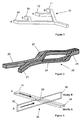
- Figure 1 shows a simple mixing device 10 having fluid supply channels 11, 12, 13, 14. Channels 11 and 13 supply fluid A and channels 12 and 14 supply fluid B. The four channels are combined to form a four layered laminate flow 15 which has three interfaces between fluid A and fluid B. The increase in the number of interfaces increases the amount of diffusion between the different fluids and therefore reduces the time required for thorough mixing to occur.
- FIG. 2 One example of a simple two layered mixing device 20 is shown in Figure 2 , in which passageways 21 and 22, containing fluid A and B respectively, are brought together in a single passage which is then split into upper 23 and lower 24 pathways, thereby creating the two layers within the device, and which are then brought back together as a four layered laminate flow 25, similar to that produced by the device of Figure 1 .
- US 5948684 discloses a fluid mixer comprising:
- such a mixer is characterised in that the second channel has a second depth different to the depth of the first channel, wherein the second channel passes through at least part of the first channel in a direction transverse to the longitudinal axis of the first channel, and wherein the cross section of the intersecting first and second channels is T-shaped along at least a portion of the intersection.
- the present invention provides a device which is capable of moving part of one or more fluids from one position in a flow to a different position in the flow to enhance mixing of the fluids.
- the device is space efficient as it does not require lengthy passageways in which the diffusion takes place as the flow pathways are relatively short compared to other known devices and therefore means that the mixing is carried out quickly.
- the network is pseudo two dimensional and there will generally be little or no crossing of the two flows. However, as the depths of the channel are caused to differ, partial crossing of the flows starts to occur. In many cases, it is desirable to have similar viscous drag on the two fluid flows and so the two channels have opposite aspect ratios; for example 2:1 and 1:2.
- aspect ratios As the aspect ratios become more elongated, more complete crossover of the two fluid flows is seen. However the channels become increasingly expensive to fabricate and the viscous drag rapidly increases. Taking these considerations into account, aspect ratios in the range between 1:5:1 and 10:1 are suitable, while aspect ratios in the region of 3:1-6:1 are the more preferred.
- the first and second channels may be elongate in cross-section typically having an aspect ratio of 5.
- the second channel passes through the first channel from a first plane to a second plane, the planes having different positions relative to the longitudinal axis of the first channel.
- the aspect ratio of the first channel may be a 90° rotation of the aspect ratio of the second channel to equalise the flow through each channel and the first and second channels preferably have substantially the same cross-sectional area.
- the total cross-sectional area of the first and second channels is preferably also substantially constant.
- the second channel may be separate from the first channel until the first plane.
- the second channel may continue beyond the first channel after the second plane.
- the second channel may extend only between the first and the second plane.
- the first and second channels may be recombined to create a multilaminar flow.
- the first and second channels may pass through a respective intermediary channel prior to recombination, each intermediary combination having substantially the same aspect ratio cross-section.
- the second channel may be formed by a gradual change in aspect ratio from the first plane.
- the first and second channels may have flow directions which are at 90° to each other.
- the first and second planes may be at different longitudinal positions in the first channel, each intermediary channel having the same aspect ratio cross-section.
- the mixer preferably comprises additional fluid routing devices as described above connected in series, such that an outlet from one device passes into the inlet of a subsequent device.
- the fluid mixer may comprise a pair of inlet passages for supplying, in use, different fluids to the first channel.
- the mixer may additionally comprise a geometric pin between each of the fluid supply passages and the first channel.
- Figure 3 shows a fluid routing device 30 having a first channel 31 and a second channel 32 which are arranged at substantially 90° to one another.
- Channel 31 carries fluid A and channel 32 carries fluid B.
- Channel 31 has a relatively wide shallow cross-section, whereas channel 32 has a narrow deep cross-section.
- Channel 32 passes through channel 31 such that, at the intersection 33, some but not significant, mixing occurs between fluid A and fluid B.
- outlet end 34 of channel 31 and outlet end 35 of the channel 32 contain mostly fluid A and fluid B respectively.
- This is a simple method of crossing two fluids over in a single layer, i.e. within the maximum depth of the deeper channel, and, as some cross contamination occurs at the intersection 33, it is most suited to use in a fluid mixer, an example of which is shown in Figure 4 , where this will be beneficial.
- a fluid mixer 40 is provided using two of the fluid routers 30 shown in Figure 3 and which have been applied to the network of passages 11, 12, 13, 14 from Figure 1 , via a 90° change in aspect ratio, to enable this construction to be formed from a single layer, thereby reducing the manufacturing costs, and the complexity of the design as only a single reservoir is required for each fluid A and B. In this way, a four layered laminate flow 15 is produced at the outlet of mixer 40.
- FIG. 5 A further example of a device according to the invention is shown in Figures 5, 6 and 7 in which a fluid mixing unit 50 includes supply passages 51, 52 which are combined at an intersection 53 to form an inlet passage 54.
- a wide, shallow first channel 55 extends from the inlet passage 54 and, at a first point 56, a narrow, deep second channel 57 is formed, in this example by a step change 58.
- the second channel 57 moves across the first channel 55 until, at a second point 59, it separates from the first channel 55.
- the first and second channels are then fed into intermediary channels 60 which recombine to form a passageway 61, which contains a four way laminar flow as shown in Figure 6 .
- passageway 61 The length of passageway 61 will be dependent upon the fluids used and their flow rate.
- passageway 61 may be shaped so that it becomes narrower and deeper than at the point at which the channels 60 merge.
- Figure 6 shows the location of the different fluids supplied by passageways 51 and 52 at different cross-sections through the mixer 50 of Figure 5 , and it will be appreciated that between first point 56 and second point 59, the first channel 55 and second channels 57 intersect with each other.
- the square cross-section inlet passage 54 transforms, at first point 56, via a step change 58, although this may be a gradual change, into a T-shaped cross-section.
- plural mixing units 50 shown in Figure 5 can be provided in series, each approximately doubling the number of interfaces, thereby introducing an exponential relationship between the numberof mixer units and the number of interfaces.
- priming parallel structures at very low flow rates can be problematic.
- the present invention is resistant to these problems due to its modular construction, but it is still desirable to improve the priming to make use of every unit in the chain, thereby minimising dead volume and chip area.
- Techniques such as CO 2 priming and the use of a surfactant to solve these problems are well known, but the introduction of extra chemical species to a fluid can be undesirable in sensitive chemical systems.
- Both pins 70, 80 incorporate flow restrictions 71, 81 which pin the first fluid to reach the node until the second fluid arrives at the node. This occurs because, once fluid has reached the flow restriction in one passage, the fluid meniscus forms across the restriction, thereby increasing the resistance to flow. Thus, fluid will flow through the other of the passages, as it has no impediment to the flow, until its meniscus also reaches the flow restriction. At this time, one fluid breaks through one of the restrictions 71, 81 and begins flowing, and this will destroy the remaining pin, thereby ensuring both parallel arms of the structure are fully primed.
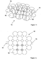
- a simple geometric bubble trap 90 placed after the combination of fluids can be used to capture these bubbles and to prevent them from entering the fluidic circuit where they may cause blockages.
- a simple design compatible with a single fluidic layer is shown in Figures 11 and 12 and comprises an array of pillars 91 which offer many parallel paths from the entrance to the exit. In such a structure bubbles will become trapped in the voids 92, before entering the mixer via channel 54.
Landscapes
- Chemical & Material Sciences (AREA)
- Chemical Kinetics & Catalysis (AREA)
- Dispersion Chemistry (AREA)
- Physical Or Chemical Processes And Apparatus (AREA)
Claims (22)
- Mélangeur de liquide (50) comportant :un dispositif d'acheminement de liquide microfluidique à une seule couche (30) ayant :un premier canal (55) ayant une section transversale d'un premier rapport de forme et d'une première profondeur et ayant un axe longitudinal ; etun second canal (57) ayant une section transversale d'un second rapport de forme différent ; dans lequel le second canal (57) traverse au moins une partie du premier canal (55) dans une direction transversale par rapport à l'axe longitudinal du premier canal, etun moyen d'alimentation en liquide (51, 52, 54) destiné à alimenter du liquide devant être mélangé dans chaque canal et qui est raccordé au dispositif d'acheminement de liquide microfluidique à une seule couche, caractérisé en ce quele second canal (57) a une seconde profondeur différente de la profondeur du premier canal (55), etla section transversale des premier (55) et second (57) canaux croisés est en forme de T le long d'au moins une partie de l'intersection.
- Mélangeur (50) selon la revendication 1, dans lequel le second canal (57) traverse le premier canal (55) depuis un premier plan (56) jusqu'à une second plan (59), les plans ayant différentes positions par rapport à l'axe longitudinal du premier canal.
- Mélangeur (50) selon l'une quelconque des revendications précédentes, dans lequel les premier (55) et second (57) canaux sont allongés en termes de section transversale.
- Mélangeur (50) selon l'une quelconque des revendications précédentes, dans lequel le rapport de forme du premier canal (55) est une rotation de 90° du rapport de forme du second canal (57).
- Mélangeur (50) selon l'une quelconque des revendications précédentes, dans lequel les premier (55) et second (57) canaux ont sensiblement la même section transversale.
- Mélangeur (50) selon l'une quelconque des revendications précédentes, dans lequel la section transversale totale des premier (55) et second (57) canaux est sensiblement constante.
- Mélangeur (50) selon la revendication 1, dans lequel les rapports de forme des deux canaux (55, 57) sont situés dans une plage entre 1,5:1 et: 10:1.
- Mélangeur (50) selon la revendication 7, dans lequel les rapports de forme des deux canaux (55, 57) sont situés dans une plage entre 3:1 et 6:1.
- Mélangeur (50) selon l'une quelconque des revendications 2 à 8, dans lequel le second canal (57) est séparé du premier canal (55) jusqu'au premier plan (56).
- Mélangeur (50) selon l'une quelconque des revendications 2 à 9, dans lequel le second canal (57) continue au-delà du premier canal (55) après le second plan.
- Mélangeur (50) selon l'une quelconque des revendications 2 à 8, dans lequel le second canal (57) s'étend uniquement entre les premier et second plans.
- Mélangeur (50) selon l'une quelconque des revendications 2 à 11, dans lequel le second canal (57) est formé par un changement progressif au niveau du rapport de forme depuis le premier plan.
- Mélangeur (50) selon l'une quelconque des revendications 1 à 11, comportant par ailleurs, au niveau du premier plan, un gradin (58) qui signifie le début du second canal (57).
- Mélangeur (50) selon l'une quelconque des revendications 2 à 11 et 13 et 14 quand ne dépendant pas de la revendication 10, comportant par ailleurs, au niveau du second plan (59), un gradin qui indique la fin du second canal.
- Mélangeur (50) selon l'une quelconque des revendications précédentes, dans lequel les premier (55) et second (57) canaux ont des directions d'écoulement qui sont à 90° l'un par rapport à l'autre.
- Mélangeur (50) selon l'une quelconque des revendications 2 à 12, dans lequel les premier (56) et second (59) plans sont en différentes positions longitudinales dans le premier canal (55).
- Mélangeur (50) selon la revendication 10, dans lequel les premier (55) et second (57) canaux sont recombinés.
- Mélangeur (50) selon la revendication 17, dans lequel les premier (55) et second (57) canaux traversent un canal intermédiaire respectif (60) avant la recombinaison.
- Mélangeur (40) selon la revendication 18, dans lequel les canaux intermédiaires (60) ont la même section transversale de rapport de forme.
- Mélangeur (40) selon l'une quelconque des revendications précédentes, comportant par ailleurs des dispositifs d'acheminement de liquide supplémentaires (30) raccordés en série.
- Mélangeur (40) selon l'une quelconque des revendications précédentes, comportant par ailleurs une paire de passages d'admission (51, 52) pour alimenter, lors de l'utilisation, différents liquides dans le premier canal (55).
- Mélangeur (40) selon la revendication 21, comportant par ailleurs une broche géométrique (70, 80) entre chacun des passage d'alimentation en liquide (51, 50) et le premier canal (55).
Priority Applications (1)
| Application Number | Priority Date | Filing Date | Title |
|---|---|---|---|
| EP03798242.8A EP1542922B1 (fr) | 2002-09-24 | 2003-09-23 | Dispositif d'acheminement de liquide |
Applications Claiming Priority (4)
| Application Number | Priority Date | Filing Date | Title |
|---|---|---|---|
| EP02256607 | 2002-09-24 | ||
| EP20020256607 EP1403209A1 (fr) | 2002-09-24 | 2002-09-24 | Dispositif d'acheminement de fluide |
| EP03798242.8A EP1542922B1 (fr) | 2002-09-24 | 2003-09-23 | Dispositif d'acheminement de liquide |
| PCT/GB2003/004045 WO2004028954A1 (fr) | 2002-09-24 | 2003-09-23 | Dispositif d'acheminement de liquide |
Publications (2)
| Publication Number | Publication Date |
|---|---|
| EP1542922A1 EP1542922A1 (fr) | 2005-06-22 |
| EP1542922B1 true EP1542922B1 (fr) | 2013-05-15 |
Family
ID=31970458
Family Applications (2)
| Application Number | Title | Priority Date | Filing Date |
|---|---|---|---|
| EP20020256607 Withdrawn EP1403209A1 (fr) | 2002-09-24 | 2002-09-24 | Dispositif d'acheminement de fluide |
| EP03798242.8A Expired - Lifetime EP1542922B1 (fr) | 2002-09-24 | 2003-09-23 | Dispositif d'acheminement de liquide |
Family Applications Before (1)
| Application Number | Title | Priority Date | Filing Date |
|---|---|---|---|
| EP20020256607 Withdrawn EP1403209A1 (fr) | 2002-09-24 | 2002-09-24 | Dispositif d'acheminement de fluide |
Country Status (4)
| Country | Link |
|---|---|
| US (1) | US7207345B2 (fr) |
| EP (2) | EP1403209A1 (fr) |
| AU (1) | AU2003264901A1 (fr) |
| WO (1) | WO2004028954A1 (fr) |
Families Citing this family (21)
| Publication number | Priority date | Publication date | Assignee | Title |
|---|---|---|---|---|
| JP4002892B2 (ja) * | 2002-02-18 | 2007-11-07 | ダンフォス アクチーセルスカブ | 液体態様の薬物を投与するためのデバイス |
| RU2336123C1 (ru) * | 2006-12-29 | 2008-10-20 | Александр Николаевич Лебедев | Пластинчатый многоканальный кавитационный реактор |
| FR2938778A1 (fr) * | 2008-11-26 | 2010-05-28 | Centre Nat Rech Scient | Contacteur pour la realisation d'operations de transfert thermique,de melange et/ou de reactions chimiques entre fluides. |
| KR101005676B1 (ko) * | 2008-11-27 | 2011-01-05 | 인하대학교 산학협력단 | 수동형 미세혼합기 |
| US20100282766A1 (en) * | 2009-05-06 | 2010-11-11 | Heiko Arndt | Low-Dead Volume Microfluidic Component and Method |
| US8230744B2 (en) | 2009-05-06 | 2012-07-31 | Cequr Sa | Low-dead volume microfluidic circuit and methods |
| WO2011078790A1 (fr) * | 2009-12-23 | 2011-06-30 | Agency For Science, Technology And Research | Appareil de mélange de type microfluidique et procédé afférent |
| US9211378B2 (en) | 2010-10-22 | 2015-12-15 | Cequr Sa | Methods and systems for dosing a medicament |
| KR20120063162A (ko) * | 2010-12-07 | 2012-06-15 | 삼성전자주식회사 | 유전자 분석 장치 및 이를 이용한 유전자 분석 방법 |
| US20120167410A1 (en) * | 2010-12-21 | 2012-07-05 | Basf Se | Spray drying techniques |
| JP5963410B2 (ja) * | 2011-08-11 | 2016-08-03 | キヤノン株式会社 | 流路デバイスおよび流体の混合方法 |
| KR101300485B1 (ko) * | 2011-10-21 | 2013-09-02 | 인하대학교 산학협력단 | 수동형 미세 혼합기 |
| WO2014047236A2 (fr) * | 2012-09-21 | 2014-03-27 | President And Fellows Of Harvard College | Systèmes et procédés de séchage par atomisation dans des systèmes microfluidiques et d'autres systèmes |
| KR101432729B1 (ko) * | 2012-12-24 | 2014-08-21 | 인하대학교 산학협력단 | 원반형의 혼합부와 교차되는 혼합채널을 가진 미세혼합기 |
| CN104138728B (zh) * | 2014-04-17 | 2016-01-27 | 西北工业大学 | 一种桥式结构的分割重组被动式微混合器 |
| US11185830B2 (en) | 2017-09-06 | 2021-11-30 | Waters Technologies Corporation | Fluid mixer |
| EP4013539A1 (fr) | 2019-08-12 | 2022-06-22 | Waters Technologies Corporation | Mélangeur pour système de chromatographie |
| US11988647B2 (en) | 2020-07-07 | 2024-05-21 | Waters Technologies Corporation | Combination mixer arrangement for noise reduction in liquid chromatography |
| US11898999B2 (en) | 2020-07-07 | 2024-02-13 | Waters Technologies Corporation | Mixer for liquid chromatography |
| US11821882B2 (en) | 2020-09-22 | 2023-11-21 | Waters Technologies Corporation | Continuous flow mixer |
| EP4341681B1 (fr) | 2021-05-20 | 2025-12-24 | Waters Technologies Corporation | Mélangeur à écoulement divisé à dispersion égale |
Family Cites Families (8)
| Publication number | Priority date | Publication date | Assignee | Title |
|---|---|---|---|---|
| US4908112A (en) * | 1988-06-16 | 1990-03-13 | E. I. Du Pont De Nemours & Co. | Silicon semiconductor wafer for analyzing micronic biological samples |
| US5948684A (en) * | 1997-03-31 | 1999-09-07 | University Of Washington | Simultaneous analyte determination and reference balancing in reference T-sensor devices |
| BR9710052A (pt) * | 1996-06-28 | 2000-01-11 | Caliper Techn Corp | Sistema microfluido com compensação para polarização eletroforética, eletropipetador, processos para introduzir materiais a partir de uma série de fontes em um sistema microfluido, para distribuir de maneira controlável uma corrente de fluido e para transportar amostras de fluido, sistema de amostragem, emprego de um substrato, emprego de um sistema microfluido, e, substrato. |
| US6136272A (en) * | 1997-09-26 | 2000-10-24 | University Of Washington | Device for rapidly joining and splitting fluid layers |
| US5842787A (en) * | 1997-10-09 | 1998-12-01 | Caliper Technologies Corporation | Microfluidic systems incorporating varied channel dimensions |
| US6290065B1 (en) * | 1998-11-13 | 2001-09-18 | Mesosystems Technology, Inc. | Micromachined virtual impactor |
| EP1065378B1 (fr) * | 1999-06-28 | 2002-04-03 | California Institute of Technology | Systemes de micropompes et microsoupapes elastomeriques |
| WO2002011888A2 (fr) * | 2000-08-07 | 2002-02-14 | Nanostream, Inc. | Melangeur fluidique pour systeme microfluidique |
-
2002
- 2002-09-24 EP EP20020256607 patent/EP1403209A1/fr not_active Withdrawn
-
2003
- 2003-09-23 WO PCT/GB2003/004045 patent/WO2004028954A1/fr not_active Ceased
- 2003-09-23 AU AU2003264901A patent/AU2003264901A1/en not_active Abandoned
- 2003-09-23 US US10/528,576 patent/US7207345B2/en not_active Expired - Fee Related
- 2003-09-23 EP EP03798242.8A patent/EP1542922B1/fr not_active Expired - Lifetime
Also Published As
| Publication number | Publication date |
|---|---|
| EP1403209A1 (fr) | 2004-03-31 |
| US7207345B2 (en) | 2007-04-24 |
| WO2004028954A1 (fr) | 2004-04-08 |
| EP1542922A1 (fr) | 2005-06-22 |
| AU2003264901A1 (en) | 2004-04-19 |
| US20060157129A1 (en) | 2006-07-20 |
Similar Documents
| Publication | Publication Date | Title |
|---|---|---|
| EP1542922B1 (fr) | Dispositif d'acheminement de liquide | |
| JP3694877B2 (ja) | マイクロ混合器 | |
| CN103890397B (zh) | 具有互连的微流体器件 | |
| JP7175547B2 (ja) | プログラマブル・マイクロ流体ノードを備えたカスタマイズ可能なマイクロ流体デバイス | |
| Lee et al. | Synchronized reinjection and coalescence of droplets in microfluidics | |
| WO2003098218A1 (fr) | Conception de systeme microfluidique a canaux multiples avec distribution d'ecoulement fluidique equilibree | |
| US20160214108A1 (en) | Microfluidic serial dilution platform based well-plate using an oil-free immiscible phase driven by manual or electronic pipettors | |
| AU2021254626B2 (en) | An arrangement for mixing fluids in a capillary driven fluidic system | |
| CN106669513B (zh) | 浓度梯度生成装置及一步生成浓度梯度的方法 | |
| US7691331B2 (en) | Microfluidic flow device and method for use thereof | |
| AU2018257567A1 (en) | Metering arrangement in a capillary driven fluid system and method for the same | |
| US10556233B2 (en) | Microfluidic device with multi-level, programmable microfluidic node | |
| JP2007139782A (ja) | 異なる滞留時間の流体搬送機構を使用するデバイスおよび方法 | |
| EP1724007B1 (fr) | Dispositif mélangeur pour fluides utilisant des canaux transversaux | |
| US20220187174A1 (en) | Microfluidic devices with capillary dilutors | |
| CN119140185A (zh) | 微流控芯片 | |
| JP2026000768A (ja) | 混合装置 | |
| JP2005118779A (ja) | 流体の吐出路構造 | |
| KR100860872B1 (ko) | 단층형 마이크로채널 | |
| US20200306751A1 (en) | Microfluidic device | |
| JP2006326407A (ja) | マイクロミキサ |
Legal Events
| Date | Code | Title | Description |
|---|---|---|---|
| PUAI | Public reference made under article 153(3) epc to a published international application that has entered the european phase |
Free format text: ORIGINAL CODE: 0009012 |
|
| 17P | Request for examination filed |
Effective date: 20050411 |
|
| AK | Designated contracting states |
Kind code of ref document: A1 Designated state(s): AT BE BG CH CY CZ DE DK EE ES FI FR GB GR HU IE IT LI LU MC NL PT RO SE SI SK TR |
|
| AX | Request for extension of the european patent |
Extension state: AL LT LV MK |
|
| DAX | Request for extension of the european patent (deleted) | ||
| RBV | Designated contracting states (corrected) |
Designated state(s): DE FR GB |
|
| 17Q | First examination report despatched |
Effective date: 20080515 |
|
| REG | Reference to a national code |
Ref country code: DE Ref legal event code: R079 Ref document number: 60344079 Country of ref document: DE Free format text: PREVIOUS MAIN CLASS: B81B0001000000 Ipc: B01F0005060000 |
|
| GRAP | Despatch of communication of intention to grant a patent |
Free format text: ORIGINAL CODE: EPIDOSNIGR1 |
|
| RIC1 | Information provided on ipc code assigned before grant |
Ipc: B01F 13/00 20060101ALI20130122BHEP Ipc: B01F 5/06 20060101AFI20130122BHEP |
|
| GRAS | Grant fee paid |
Free format text: ORIGINAL CODE: EPIDOSNIGR3 |
|
| GRAA | (expected) grant |
Free format text: ORIGINAL CODE: 0009210 |
|
| AK | Designated contracting states |
Kind code of ref document: B1 Designated state(s): DE FR GB |
|
| REG | Reference to a national code |
Ref country code: GB Ref legal event code: FG4D |
|
| REG | Reference to a national code |
Ref country code: DE Ref legal event code: R096 Ref document number: 60344079 Country of ref document: DE Effective date: 20130711 |
|
| PLBE | No opposition filed within time limit |
Free format text: ORIGINAL CODE: 0009261 |
|
| STAA | Information on the status of an ep patent application or granted ep patent |
Free format text: STATUS: NO OPPOSITION FILED WITHIN TIME LIMIT |
|
| 26N | No opposition filed |
Effective date: 20140218 |
|
| PGFP | Annual fee paid to national office [announced via postgrant information from national office to epo] |
Ref country code: DE Payment date: 20140331 Year of fee payment: 11 |
|
| REG | Reference to a national code |
Ref country code: DE Ref legal event code: R097 Ref document number: 60344079 Country of ref document: DE Effective date: 20140218 |
|
| PGFP | Annual fee paid to national office [announced via postgrant information from national office to epo] |
Ref country code: GB Payment date: 20140319 Year of fee payment: 11 |
|
| PGFP | Annual fee paid to national office [announced via postgrant information from national office to epo] |
Ref country code: FR Payment date: 20140328 Year of fee payment: 11 |
|
| REG | Reference to a national code |
Ref country code: DE Ref legal event code: R119 Ref document number: 60344079 Country of ref document: DE |
|
| GBPC | Gb: european patent ceased through non-payment of renewal fee |
Effective date: 20140923 |
|
| REG | Reference to a national code |
Ref country code: DE Ref legal event code: R119 Ref document number: 60344079 Country of ref document: DE Effective date: 20150401 |
|
| REG | Reference to a national code |
Ref country code: FR Ref legal event code: ST Effective date: 20150529 |
|
| PG25 | Lapsed in a contracting state [announced via postgrant information from national office to epo] |
Ref country code: DE Free format text: LAPSE BECAUSE OF NON-PAYMENT OF DUE FEES Effective date: 20150401 Ref country code: GB Free format text: LAPSE BECAUSE OF NON-PAYMENT OF DUE FEES Effective date: 20140923 |
|
| PG25 | Lapsed in a contracting state [announced via postgrant information from national office to epo] |
Ref country code: FR Free format text: LAPSE BECAUSE OF NON-PAYMENT OF DUE FEES Effective date: 20140930 |