US6290065B1 - Micromachined virtual impactor - Google Patents
Micromachined virtual impactor Download PDFInfo
- Publication number
- US6290065B1 US6290065B1 US09/494,962 US49496200A US6290065B1 US 6290065 B1 US6290065 B1 US 6290065B1 US 49496200 A US49496200 A US 49496200A US 6290065 B1 US6290065 B1 US 6290065B1
- Authority
- US
- United States
- Prior art keywords
- passage
- flow
- major
- minor
- plate
- Prior art date
- Legal status (The legal status is an assumption and is not a legal conclusion. Google has not performed a legal analysis and makes no representation as to the accuracy of the status listed.)
- Expired - Lifetime
Links
- 238000000926 separation method Methods 0.000 claims abstract description 147
- 239000002245 particle Substances 0.000 claims abstract description 119
- 239000012530 fluid Substances 0.000 claims abstract description 98
- 238000000034 method Methods 0.000 claims description 15
- 238000011144 upstream manufacturing Methods 0.000 claims description 12
- 238000004891 communication Methods 0.000 claims description 8
- 238000007789 sealing Methods 0.000 claims description 4
- 239000011800 void material Substances 0.000 description 8
- 239000000443 aerosol Substances 0.000 description 7
- 229910052751 metal Inorganic materials 0.000 description 7
- 239000002184 metal Substances 0.000 description 7
- 239000000463 material Substances 0.000 description 5
- 239000004033 plastic Substances 0.000 description 5
- 229920003023 plastic Polymers 0.000 description 5
- 238000013461 design Methods 0.000 description 4
- 238000001514 detection method Methods 0.000 description 4
- 238000003754 machining Methods 0.000 description 4
- 238000005459 micromachining Methods 0.000 description 4
- 229910000831 Steel Inorganic materials 0.000 description 3
- RTAQQCXQSZGOHL-UHFFFAOYSA-N Titanium Chemical compound [Ti] RTAQQCXQSZGOHL-UHFFFAOYSA-N 0.000 description 3
- 229910052782 aluminium Inorganic materials 0.000 description 3
- XAGFODPZIPBFFR-UHFFFAOYSA-N aluminium Chemical compound [Al] XAGFODPZIPBFFR-UHFFFAOYSA-N 0.000 description 3
- 238000000151 deposition Methods 0.000 description 3
- 230000008021 deposition Effects 0.000 description 3
- 239000007788 liquid Substances 0.000 description 3
- 238000000465 moulding Methods 0.000 description 3
- 239000010959 steel Substances 0.000 description 3
- 239000010936 titanium Substances 0.000 description 3
- 229910052719 titanium Inorganic materials 0.000 description 3
- 244000126822 Albuca minor Species 0.000 description 2
- 230000001154 acute effect Effects 0.000 description 2
- 230000008901 benefit Effects 0.000 description 2
- 230000008859 change Effects 0.000 description 2
- 238000005553 drilling Methods 0.000 description 2
- 230000008569 process Effects 0.000 description 2
- 239000003570 air Substances 0.000 description 1
- 238000004458 analytical method Methods 0.000 description 1
- 239000003124 biologic agent Substances 0.000 description 1
- 238000005266 casting Methods 0.000 description 1
- 239000002575 chemical warfare agent Substances 0.000 description 1
- 239000012141 concentrate Substances 0.000 description 1
- 238000011109 contamination Methods 0.000 description 1
- 230000003247 decreasing effect Effects 0.000 description 1
- 230000007123 defense Effects 0.000 description 1
- 238000004070 electrodeposition Methods 0.000 description 1
- 238000005516 engineering process Methods 0.000 description 1
- 239000003344 environmental pollutant Substances 0.000 description 1
- 239000010419 fine particle Substances 0.000 description 1
- 238000005194 fractionation Methods 0.000 description 1
- 239000007789 gas Substances 0.000 description 1
- 230000006872 improvement Effects 0.000 description 1
- 238000011044 inertial separation Methods 0.000 description 1
- 238000000608 laser ablation Methods 0.000 description 1
- 238000001459 lithography Methods 0.000 description 1
- 238000004519 manufacturing process Methods 0.000 description 1
- 238000005259 measurement Methods 0.000 description 1
- 150000002739 metals Chemical class 0.000 description 1
- 238000012986 modification Methods 0.000 description 1
- 230000004048 modification Effects 0.000 description 1
- 238000005457 optimization Methods 0.000 description 1
- 238000000206 photolithography Methods 0.000 description 1
- 238000001020 plasma etching Methods 0.000 description 1
- 231100000719 pollutant Toxicity 0.000 description 1
- 238000005070 sampling Methods 0.000 description 1
- 238000004088 simulation Methods 0.000 description 1
- 239000002689 soil Substances 0.000 description 1
- 239000007787 solid Substances 0.000 description 1
- 230000007704 transition Effects 0.000 description 1
- 238000005406 washing Methods 0.000 description 1
- XLYOFNOQVPJJNP-UHFFFAOYSA-N water Substances O XLYOFNOQVPJJNP-UHFFFAOYSA-N 0.000 description 1
Images


Classifications
-
- G—PHYSICS
- G01—MEASURING; TESTING
- G01N—INVESTIGATING OR ANALYSING MATERIALS BY DETERMINING THEIR CHEMICAL OR PHYSICAL PROPERTIES
- G01N15/00—Investigating characteristics of particles; Investigating permeability, pore-volume or surface-area of porous materials
- G01N15/02—Investigating particle size or size distribution
- G01N15/0255—Investigating particle size or size distribution with mechanical, e.g. inertial, classification, and investigation of sorted collections
-
- B—PERFORMING OPERATIONS; TRANSPORTING
- B01—PHYSICAL OR CHEMICAL PROCESSES OR APPARATUS IN GENERAL
- B01D—SEPARATION
- B01D45/00—Separating dispersed particles from gases or vapours by gravity, inertia, or centrifugal forces
- B01D45/04—Separating dispersed particles from gases or vapours by gravity, inertia, or centrifugal forces by utilising inertia
- B01D45/08—Separating dispersed particles from gases or vapours by gravity, inertia, or centrifugal forces by utilising inertia by impingement against baffle separators
-
- G—PHYSICS
- G01—MEASURING; TESTING
- G01N—INVESTIGATING OR ANALYSING MATERIALS BY DETERMINING THEIR CHEMICAL OR PHYSICAL PROPERTIES
- G01N1/00—Sampling; Preparing specimens for investigation
- G01N1/28—Preparing specimens for investigation including physical details of (bio-)chemical methods covered elsewhere, e.g. G01N33/50, C12Q
- G01N1/40—Concentrating samples
- G01N1/4077—Concentrating samples by other techniques involving separation of suspended solids
-
- G—PHYSICS
- G01—MEASURING; TESTING
- G01N—INVESTIGATING OR ANALYSING MATERIALS BY DETERMINING THEIR CHEMICAL OR PHYSICAL PROPERTIES
- G01N1/00—Sampling; Preparing specimens for investigation
- G01N1/02—Devices for withdrawing samples
- G01N1/22—Devices for withdrawing samples in the gaseous state
- G01N1/2202—Devices for withdrawing samples in the gaseous state involving separation of sample components during sampling
- G01N1/2208—Devices for withdrawing samples in the gaseous state involving separation of sample components during sampling with impactors
-
- G—PHYSICS
- G01—MEASURING; TESTING
- G01N—INVESTIGATING OR ANALYSING MATERIALS BY DETERMINING THEIR CHEMICAL OR PHYSICAL PROPERTIES
- G01N1/00—Sampling; Preparing specimens for investigation
- G01N1/02—Devices for withdrawing samples
- G01N2001/022—Devices for withdrawing samples sampling for security purposes, e.g. contraband, warfare agents
- G01N2001/025—Devices for withdrawing samples sampling for security purposes, e.g. contraband, warfare agents postal items
-
- G—PHYSICS
- G01—MEASURING; TESTING
- G01N—INVESTIGATING OR ANALYSING MATERIALS BY DETERMINING THEIR CHEMICAL OR PHYSICAL PROPERTIES
- G01N15/00—Investigating characteristics of particles; Investigating permeability, pore-volume or surface-area of porous materials
- G01N2015/0042—Investigating dispersion of solids
- G01N2015/0046—Investigating dispersion of solids in gas, e.g. smoke
-
- G—PHYSICS
- G01—MEASURING; TESTING
- G01N—INVESTIGATING OR ANALYSING MATERIALS BY DETERMINING THEIR CHEMICAL OR PHYSICAL PROPERTIES
- G01N15/00—Investigating characteristics of particles; Investigating permeability, pore-volume or surface-area of porous materials
- G01N15/01—Investigating characteristics of particles; Investigating permeability, pore-volume or surface-area of porous materials specially adapted for biological cells, e.g. blood cells
- G01N2015/019—Biological contaminants; Fouling
-
- G—PHYSICS
- G01—MEASURING; TESTING
- G01N—INVESTIGATING OR ANALYSING MATERIALS BY DETERMINING THEIR CHEMICAL OR PHYSICAL PROPERTIES
- G01N15/00—Investigating characteristics of particles; Investigating permeability, pore-volume or surface-area of porous materials
- G01N15/02—Investigating particle size or size distribution
- G01N2015/0288—Sorting the particles
Definitions
- This invention pertains to the field of separating particles from a fluid stream, and more particularly to a combination of a nozzle and virtual impactor steps used to separate a particle-laden fluid stream into a portion containing a substantially greater concentration of particles and another portion containing substantially fewer particles.
- the separation and collection of particles/aerosols from an airstream or other fluid streams are of concern in two contexts: first, for purposes of analyzing the type and concentration of such particles/aerosols entrained in the fluid and, second, for clearing particles/aerosols from the fluid stream. Additionally, it is sometimes important to classify particles entrained in a fluid stream by size. For example, this technology may be employed in the detection of airborne biological or chemical warfare agents, the detection of biological contamination in confined spaces, such as aircraft or hospitals, or the detection of industrial pollutants (either in ambient fluid or in the effluent of smokestacks).
- Impactors have been used for collecting aerosol particles for many decades.
- a stream of fluid containing the particles was accelerated toward an impactor plate. Due to their inertia, the particles hit the impactor plate and were collected there while the fluid was deflected to the side. With these types of impactors, only heavy particles were collected while particles below a certain “cut size” were carried away by the fluid stream.
- Virtual impactors may operate on a number of different principles, but all avoid actual “impact” as a means to separate particles from a fluid in which the particles are entrained and rely on differences in particle mass to induce inertial separation.
- a particle-laden fluid stream is directed toward a surface presenting an obstruction to the forward movement of the fluid stream.
- the surface includes a void at the point where the particles would normally impact the surface.
- fine particles remain entrained in the deflected major portion of the fluid stream.
- Heavier or more dense particles fail to change direction and are collected in a region of relatively stagnant fluid (a “dead air zone”) that is created near the surface.
- the heavier particles entrained in a minor portion of the fluid stream enter the void defined through the surface, where they can be captured or analyzed.
- a separation plate employed for separating a fluid stream into a major flow and a minor flow is defined.
- the major flow includes a minor portion of particles that are above a predetermined size
- the minor flow includes a major portion of the particles that are above the predetermined size.
- the separation plate includes a block in which is defined a laterally extending passage having an inlet disposed on one edge of the block and an outlet disposed on an opposite edge of the block.
- This laterally extending passage has a lateral dimension that is substantially greater than a transverse dimension of the passage.
- Opposed surfaces of the passage between which the transverse dimension of the passage is defined generally converge toward each other within the block, so that the outlet has a substantially smaller cross-sectional area than the inlet.
- a transverse, laterally extending slot is defined within the block and is in fluid communication with a portion of the passage that has the substantially smaller cross-sectional area.
- a major flow outlet port is also defined in the block, in fluid communication with the transverse, laterally extending slot. The major flow enters the slot and exiting the block through the major flow outlet port, while the minor flow exits the block through the outlet of the passage. The major flow carries the minor portion of the particles and the minor flow carries the major portion of the particles.
- Another transverse, laterally extending slot is preferably disposed opposite the slot within the block; and another major flow outlet port is in fluid communication with the other slot to provide a further fluid path for the major flow carrying the minor portion of the particles.
- the block preferably comprises a first plate and a second plate that are coupled together, with a passage being defined between facing surfaces of the first plate and the second plate.
- the facing surfaces of the first plate and the second plate are preferably joined at each end of the passage, sealing the ends of the passage. A portion of the passage is thus defined in a facing surface of the first plate, and another portion of the passage is defined in a facing surface of the second plate.
- the passage converges with a defined transverse profile toward a receiving nozzle at an entrance to a minor flow portion of the passage.
- the slot is then disposed distally of but proximate to the receiving nozzle.
- a lateral dimension of the passage is a function of a desired flow of fluid through the inlet of the passage.
- a plurality of the separation plates can be arrayed to accommodate a desired flow of fluid.
- Another aspect of the present invention is directed to a method for separating a fluid flow in which particles are entrained, generally consistent with the above description.
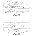
- FIG. 1A is a plan view of a separation plate of the present invention
- FIG. 1B is a cross-sectional view of the separation plate taken along line 1 B— 1 B of FIG. 1A;
- FIG. 1C is an enlarged view of a pair of a nozzle and a virtual impactor at section 1 C of FIG. 1A;
- FIG. 1D is an enlarged view of another configuration of a pair of a nozzle and a virtual impactor
- FIG. 2A is a schematic cross-sectional view of a virtual impact collector incorporating another configuration of a separation plate of the present invention
- FIG. 2B is a schematic perspective view of an alternative configuration of a virtual impact collector in accordance with the present invention.
- FIG. 3A is a plan view of a virtual impact collector incorporating plural pairs of a nozzle and a virtual impactor arranged radially;
- FIG. 3B is a cross-sectional view of the virtual impact collector taken along line 3 B— 3 B of FIG. 3A;
- FIG. 4A is a plan view of another configuration of a separation plate in accordance with the present invention.
- FIG. 4B is a cross-sectional view of the separation plate taken along line 4 B— 4 B of FIG. 4A;
- FIG. 4C is a cross-sectional view of the separation plate taken along line 4 C— 4 C of FIG. 4A;
- FIG. 5A is an isometric view of yet another alternative embodiment of a separation plate in accord with the present invention.
- FIG. 5B is a cross-sectional view of the separation plate of FIG. 5A, showing additional separation plates arrayed on each side in phantom view;
- FIG. 6A is an isometric view of still another alternative embodiment of a separation plate in accord with the present invention.
- FIG. 6B is a cross-sectional view of the separation plate of FIG. 6A, showing additional separation plates arrayed on each side in phantom view;
- FIG. 7 is a cross-sectional view of a separation plate like that shown in FIGS. 5A and 5B, but having a slightly modified passage through which the fluid flows to optimize the efficiency of separation over a broader range of particle sizes.
- micro is applied generally to components that have submillimeter-sized features.
- Microcomponents are fabricated using micromachining techniques known in the art, such as micromilling, photolithography, deep ultraviolet (or x-ray) lithography, electrodeposition, electrodischarge machining (EDM), laser ablation, and reactive or non-reactive ion etching.
- micromachining techniques known in the art, such as micromilling, photolithography, deep ultraviolet (or x-ray) lithography, electrodeposition, electrodischarge machining (EDM), laser ablation, and reactive or non-reactive ion etching.
- Particle any separately identifiable solid, liquid, aerosol, or other component entrained in a fluid stream that has a greater mass than the fluid forming the fluid stream, and is the subject of separation and collection for analysis.
- mass density of particles is assumed to be approximately 1 gm/cm 3 . It is contemplated that the particles may arise from sampling almost any source, including but not limited to, air, water, soil, and surfaces.
- Fluid any fluid susceptible to fluid flow, which may comprise liquids or gases, and which may entrain foreign particles therein. Unless otherwise noted, fluid shall mean the ambient fluid containing unconcentrated particles for collection, not the fluid into which the particles are concentrated after collection or capture.
- FIGS. 1A, 1 B, and 1 C illustrate the first embodiment of a virtual impact separation plate 10 formed in accordance with the present invention.
- Separation plate 10 may be formed of any material suitable for micromachining, such as plastics and metals.
- Separation plate 10 includes a first surface 10 a and an opposing second surface 10 b .
- the first surface 10 a includes plural pairs of a nozzle 14 and a virtual impactor 16 (FIG. 1 C).
- Each nozzle 14 includes an inlet end 14 a and an outlet end 14 b , and is defined between adjacent nozzle projections 18 having a height “H” (FIG. 1 B). Two nozzle projections 18 cooperate to define one nozzle 14 .
- Each nozzle projection 18 includes two sidewalls 20 that are configured to define one side of a nozzle 14 ,which comprise a telescoping design that generally tapers from inlet end 14 a to outlet end 14 b .
- Nozzle projection 18 further includes two generally concave walls 22 at its downstream end that are positioned to provide nozzle projection 18 with a tapered downstream “tail.”
- a tapered downstream tail In contrast to a tapered downstream tail, another of the embodiments described below that is actually more preferred includes stepped transitions that reduce the size of the passage at its outlet.
- upstream and downstream are used to refer to the direction of a fluid stream 23 flowing along the separation plate of the present invention.
- Each virtual impactor 16 comprises a pair of generally fin-shaped projections 24 having height “H.”
- Fin-shaped projection 24 includes an inner wall 26 and a generally convex outer wall 28 .
- Inner walls 26 of fin-shaped projections 24 in a pair are spaced apart and face each other to define an upstream minor flow passage 30 a therebetween.
- Convex outer walls 28 of the pair of fin-shaped projections 24 cooperatively present a generally convex surface 31 facing the fluid flow direction.
- an inlet end 32 of upstream minor flow passage 30 a defines a virtual impact void through convex surface 31 ,where “virtual” impaction occurs as more fully described below.
- a width of outlet end 14 b of nozzle 14 is defined as “a,” and a width of inlet end 32 of upstream minor flow passage 30 a is defined as “b.”
- First surface 10 a of separation plate 10 may further include a plurality of virtual impactor bodies 33 extending downstream from the downstream ends of adjacent fin-shaped projections 24 of adjacent pairs of virtual impactors 16 .
- Each virtual impactor body 33 includes opposing external walls that extend downstream from the downstream ends of inner walls 26 . External walls of adjacent virtual impactor bodies 33 are spaced apart to define a downstream minor flow passage 30 b therebetween. Upstream and downstream minor flow passages 30 a and 30 b are aligned and communicate with each other to form a minor flow passage 30 .
- fin-shaped projections 24 of adjacent virtual impactors 16 and a virtual impactor body 33 may be integrally formed.
- an orifice 34 may be defined through virtual impactor body 33 adjacent to the downstream ends of convex outer walls 28 of adjacent virtual impactors 16 .
- Orifices 34 define terminal ends of passageways 36 that extend downward and downstream through separation plate 10 to second surfaces 10 b .
- orifices 34 and passageways 36 are provided merely as one example of a major flow outlet and, thus, may be replaced with any other suitable major flow outlet.
- particle laden fluid stream 23 is caused to enter inlet ends 14 a of nozzles 14 .
- Nozzles 14 aerodynamically focus and accelerate particles entrained in fluid stream 23 .
- the aerodynamically focused fluid stream 23 exiting outlet ends 14 b of nozzles 14 advances to convex surfaces 31 of virtual impactors 16 .
- Concave walls 22 of nozzle projections 18 and convex outer walls 28 of fin-shaped projections 24 cooperate to direct the major flow toward the upstream end of virtual impactor bodies 33 .
- Bodies 33 prevent the major flow from further advancing.
- orifices 34 are provided through bodies 33 , the major flow enters orifices 34 and travels through passageways 36 to second surface 10 b of separation plate 10 , where it can be exhausted or processed further.
- a minor portion (less than 50%, preferably less than approximately 10%) of fluid stream 23 containing a major portion (at least about 50%) of particles above the “cut size, ” hereinafter “minor flow, ” is collected ncar a “dead fluid” zone or a zone of nearly stagnant air created adjacent to the convex surfaces 31 of virtual impactors 16 .
- the major portion of the particles entrained in the minor flow “virtually” impact the virtual impact voids, or the inlet ends 32 of upstream minor flow passages 30 a , and enter the minor flow passages 30 .
- the minor flow travels through minor flow passages 30 and exits therefrom, enabling the particles entrained therein to be collected, analyzed, or processed further.
- Nozzles 14 contribute very little to particle loss because they have a long telescoping profile, which prevents particle deposition thereon.
- the long telescoping profile of the nozzles 14 also serves to align and accelerate particles. Focusing the particles before they enter the minor flow passage using the telescoping design may enhance the performance of the virtual impactor, since the particles in the center of the nozzle are likely to remain entrained in the minor flow.
- the term “aerodynamic focusing” refers to a geometry of a particle separator that concentrates particles toward the center of a central channel through the particle separator. Because nozzles 14 aerodynamically focus and accelerate particles in a fluid stream, virtual impactors 16 placed downstream of nozzles 14 are able to separate particles very efficiently.
- the present invention allows for employing only one layer or row of virtual impactors 16 for completing particle separation, which eliminates the chances of particles getting lost due to impact on surfaces of additional layers or rows of virtual impactors.
- the present invention further reduces particle loss on inner surfaces of minor flow passages, by allowing minor flows to advance straight through the minor flow passages upon virtual impaction, without having to change their flow direction.
- a separation plate 10 configured in accordance with the dimensions (all in inches) shown in FIGS. 1A and 1B is designed to have a cut size of 1.0 microns at a flow rate of 35 liters per minute (LPM).
- the term “cut size” means a particle diameter at which 50% of the particles of that diameter flowing along the first surface of a separation plate are separated from a fluid stream and mostly exhausted through the minor flow passages. For particles having a diameter above the cut size, preferably more than 50% of the particles flowing along the separation plate are separated. It should be understood that those skilled in the art may readily optimize separation plate 10 of the present invention to meet a specific “cut size” requirement at a predefined flow rate.
- the “cut size” of a separation plate may be modified by scaling up or down the various structures provided on the separation plate; larger nozzles with proportionally larger virtual impactors are useful in separating larger particles, while conversely smaller nozzles with proportionally smaller virtual impactors are useful in separating smaller particles.
- the “cut size” of a separation plate may also be modified by adjusting a flow rate through the separation plate. For particles having 1- to 3-micron diameters, it has been found that making “a” greater than “b” generally reduces recirculation of a minor flow upon entering minor flow passage 30 , which is preferable for efficiently separating a minor flow from a major flow. For larger particles, it may be preferable to make “b” larger than “a” to reduce pressure drop.
- FIG. 1D illustrates modified configurations of a nozzle 14 and a virtual impactor 16 , wherein inner walls 26 of fin-shaped projections 24 include a generally concave surface. Accordingly, the width of upstream minor flow passage 30 a expands from inlet end 32 toward downstream minor flow passage 30 b , which is defined between the external walls of adjacent virtual impactor bodies 33 . This configuration is advantageous in reducing particle loss onto inner walls 26 .
- a separation plate of the present invention may be easily modified to process virtually any volume of fluid stream at any flow rate, by varying the number of nozzles 14 and virtual impactors 16 provided on the separation plate. Furthermore, the throughput of separation plate 10 may be almost indefinitely modifiable by increasing or decreasing height “H” of nozzles 14 , virtual impactors 16 , and virtual impactor bodies 33 . It should be noted that height “H” of a separation plate of the invention can be freely increased without a significant increase in particle loss. This capability is made possible by the present design that allows minor flows to advance straight through without experiencing any deflected path.
- Separation plate 10 of the present invention may be readily incorporated into various particle separation/concentration apparatus.
- a virtual impact collector may be formed by placing a cover plate 42 over projections 18 , fin-shaped projections 24 , and virtual impactor bodies 33 provided on first surface 10 a .
- Cover plate 42 and first surface 10 a cooperatively define a chamber.
- Inlet ends 14 a of nozzles 14 provide an inlet through which a particle-laden fluid stream may enter the chamber.
- Minor flow passages 30 provide an outlet through which a minor flow may exit the chamber; however, an outlet through which a major flow may exit the chamber may be provided in various other ways. For example, as in FIGS.
- cover plate 42 may include a plurality of holes 44 that extend therethrough. Holes 44 are configured and arranged so that when cover plate 42 is mated with separation plate 10 , holes 44 are disposed between virtual impactors 16 and adjacent to the upstream end of virtual impactor bodies 33 , to exhaust major flows flowing around virtual impactors 16 that are blocked by bodies 33 , as indicated by an arrow. It should be understood that, in operating the virtual impact collector as described above, those skilled in the art can provide a suitable flow subsystem for causing a fluid stream to flow through the chamber.
- FIG. 21 A further example of a virtual impact collector formed in accordance with the present invention is schematically illustrated in FIG. 21 .
- separation plate 10 of FIG. 1A is joined at its opposing edges 45 to form a cylinder.
- the second surface of separation plate 10 forms the inner surface of the cylinder.
- the cylindrical separation plate 10 is coaxially slid into a tube 46 having two open ends 46 a and 46 b to form an annular chamber 47 therebetween.
- a suitable major flow outlet is provided (not shown).
- particle-laden fluid streams enter chamber 47 through the inlet ends of the nozzles defined between nozzle projections 18 , adjacent to open end 46 a .
- Minor flow passages 30 provide an outlet through which a minor flow may exit chamber 47 .
- a suitably provided major flow outlet deflects a major flow to either or both of the inner surfaces of the cylindrical separation plate 10 and/or the outer surface of tube 46 .
- FIGS. 3A and 3B schematically illustrate a virtual impact collector 10 incorporating another configuration of a separation plate 50 of the present invention and a cover plate 56 .
- Separation plate 50 includes plural pairs of nozzles 14 and virtual impactors 16 ; the virtual impactors are disposed radially inward of nozzles 14 .
- nozzle 14 which has an inlet end 14 a and an outlet end 14 b , is defined between adjacent nozzle projections 18 .
- Virtual impactor 16 comprises a pair of fin-shaped projections 24 provided downstream of, and radially inward of, outlet end 14 b of each nozzle 14 .
- fin-shaped projections 24 in each pair are spaced apart and define minor flow passage 30 therebetween.
- a plurality of virtual impactor bodies 33 in the form of a wall extend between the downstream ends of fin-shaped projections 24 of adjacent virtual impactors 16 .
- a plurality of holes 39 may be provided through separation plate 50 radially outward of virtual impactor bodies 33 and between fin-shaped projections 24 of adjacent virtual impactors 16 .
- Virtual impactors 16 and bodies 33 together define a central minor flow collection portion 54 .
- a plurality of impactor pillars 38 may be placed radially inward and downstream of minor flow passages 30 , within central minor flow collection portion 54 . Impactors 38 are employed to receive a minor flow and to collect particles thereon, as more fully described below.
- a minor flow outlet 59 may be provided through separation plate 50 near the center of central minor flow collection portion 54 .
- Separation plate 50 which is described above, may be combined with cover plate 56 to form a virtual impact collector.
- Cover plate 56 is configured to mate with separation plate 50 to define a chamber therebetween.
- cover plate 56 may include holes 58 that are configured and arranged so that when separation plate 50 and cover plate 56 are combined, holes 58 are aligned to coincide with holes 39 defined through separation plate 50 .
- cover plate 56 may include a minor flow outlet 60 defined therethrough. Minor flow outlet 60 is configured so that when cover plate 56 and separation plate 50 are combined, minor flow outlet 60 of cover plate 56 aligns with minor flow outlet 59 of separation plate 50 . Holes 39 of separation plate 50 and/or holes 58 of cover plate 56 provide a major flow outlet to the chamber. Minor flow outlet 59 of separation plate 50 and/or minor flow outlet 60 of cover plate 56 provide a minor flow exhaust to the chamber.
- particle-laden fluid streams enter nozzles 14 through inlet ends 14 a and advance radially inward.
- aerodynamically focused fluid streams advance toward virtual impactors 16 , they are separated into a minor flow and a major flow, as described above.
- the major flow flows around virtual impactors 16 , is blocked by bodies 33 , and is exhausted through either or both of holes 39 in separation plate 50 and/or holes 58 in cover plate 56 .
- the minor flow advances through minor flow passages 30 into central minor flow collection portion 54 .
- impactors 38 are provided, some of the particles entrained in the minor flow may impact and become deposited on impactors 38 .
- the particles collected on impactors 38 may be subsequently collected, for example, by washing impactors 38 with a small amount of liquid to capture the particles therein.
- An example of impactors suitable for use in conjunction with the present invention can be found in copending U.S. patent application Ser. No. 09/191,979, filed Nov. 13, 1998, concurrently with the parent case hereof, and assigned to the same assignee, which is herein expressly incorporated by reference.
- the minor flow may be exhausted from central minor flow collection portion 54 through either or both of minor flow outlets 59 and 60 .
- a plurality of the virtual impact collectors described above may be stacked together to process large amounts of fluid streams.
- the stacked virtual impact collectors include a common minor flow exhaust conduit comprising minor flow outlets 59 and 60 , and a common major flow exhaust conduit comprising holes 39 and 58 .
- FIGS. 4A, 4 B, and 4 C illustrate another embodiment of a separation plate 70 in accordance with the present invention.
- separation plate 70 includes a first surface 70 a and an opposing second surface 70 b .
- First surface 70 a is provided with a plurality of nozzle projections 18 that define nozzles 14 therebetween.
- nozzle 14 tapers from an inlet end 14 a to an outlet end 14 b .
- a generally haystack-shaped virtual impactor projection 72 is provided downstream of each outlet end 14 b .
- Virtual impactor projection 72 includes a convex leading surface 74 facing the fluid flow.
- a virtual impact void 76 is provided through convex surface 74 near its apex.
- Virtual impact void 76 defines a terminal end of a minor flow passage 78 that extends down and through separation plate 70 .
- Minor flow passage 78 and virtual impact void 76 may be formed by, for example, boring an end-mill through second surface 70 b of separation plate 70 .
- minor flow passage 78 and virtual impact void 76 may be formed by drilling a hole through separation plate 70 .
- minor flow passage 78 preferably passes through separation plate 70 at an acute angle so that a minor flow containing a major portion of particles will avoid sharp changes in direction upon entering virtual impact void 76 . It should be noted that the longer the minor flow passage 78 , the more particles may be deposited on the inner surfaces of minor flow passage 78 .
- the angle of minor flow passage 78 should be as acute as possible, the length of minor flow passage 78 cannot be indefinitely long.
- the optimum combination of the angle and the length of minor flow passage 78 is to be determined based partly on the limitations imposed by the available micromachining methods. An angle of between approximately 15° and 45°, which is possible with currently available micromachining methods, should provide satisfactory results.
- particle-laden fluid streams flow along first surface 10 a through nozzles 14 and advance toward convex surfaces 74 of virtual impactor projections 72 .
- Major flows flow around projections 72 to avoid obstruction presented by convex surfaces 74 , and continue along first surface 10 a .
- Minor flows are collected in a zone of stagnant fluid created near convex surfaces 74 , and enter virtual impact voids 76 defined through convex surfaces 74 .
- the minor flows travel through minor flow passages 78 to second surface 70 b , where they can be collected, analyzed, or processed further in any other manner desired.
- separation plate 70 of the present embodiment separates a particle-laden fluid stream into a minor flow on the second surface, and a major flow on the first surface.
- Separation plate 100 includes a central passage 102 that extends laterally across the length of the separation plate and through its width.
- the passage is defined between plates 104 a and 104 b and is machined within the facing surfaces of these two plates, which preferably comprise a metal such as steel, aluminum, or titanium, or a another suitable material such as plastic.
- the passage can be formed by molding or casting the plates from metal, or another suitable material, such as plastic.
- Passage 102 is readily formed in the surfaces of each of plates 104 a and 104 b by conventional machining techniques. Since the surfaces are fully exposed, the desired telescoping or converging configuration of the passage is readily formed.
- the passage extends from an inlet 108 , which is substantially greater in cross-sectional area due to its greater height than an outlet 106 .
- the outlet is disposed on the opposite side of the separation plate from the inlet.
- Inlet 108 tapers to a convergent nozzle 110 , which further tapers to the opening into a minor flow portion 112 of passage 102 .
- one-half the thickness of passage 102 is formed in plate 104 a
- the other half of the thickness of the passage is formed in plate 104 b .
- the portions of the passage defined in each of plates 104 a and 104 b need not be symmetrical or identical, since a desired configuration for passage 102 can be asymmetric relative to the facing opposed surfaces of the two plates.
- slots 115 a and 115 b are defined and extend transversely into the plates relative to the direction between the inlet and the outlet of passage 102 and extend laterally across separation plate 100 between the sides of the passage. Slots 115 a and 115 b respectively open into major flow outlet ports 114 a and 114 b , in the ends of plates 104 a and 104 b , as shown in FIG. 5 A.
- Threaded fastener holes 116 are disposed on opposite sides of each of major flow outlet ports 114 a and 114 b and are used for connecting a major flow manifold (not shown) that receives the major flow of fluid in which the minor portion of the particles greater than the cut size is entrained.
- Fastener holes 118 a are formed through plate 104 b adjacent to its four corners and do not include threads. Threaded fasteners (not shown) are intended to be inserted through holes 118 a and threaded into holes 118 b , which are formed at corresponding corner positions on plate 104 a . The threaded fasteners thus couple edge seals 120 on the two plates together, sealing the edges of passage 102 and connecting plates 104 a and 104 b to form separation plate 100 .
- a manifold may also be connected to the back surface of separation plate 100 overlying outlet 106 to collect the minor flow of fluid in which the major portion of particles exceeding the cut size is entrained. In FIG.
- the flow of fluid entering inlet 108 of passage 102 is indicated by the large arrow
- the major flow exiting major flow ports 114 a and 114 b is indicated by the solid line arrows
- the minor flow exiting outlet 106 of passage 102 is indicated by the dash line arrow.
- the cross-sectional profile of passage 102 as shown in FIG. 5B focuses the particle-laden fluid flow entering inlet 106 for delivery to the receiving nozzle and thus performs in much the same way as the profile used in the previous embodiments of virtual impactors.
- the desired flow through the separation plate will determine the width of passage 102 , as measured along the longitudinal axis of the separation plate, between scaled edges 120 . Additional fluid flow can also be accommodated by providing a plurality of the separation plates in an array, which will also avoid using extremely long and thin structures, which may not fit within an available space.
- FIG. 5B illustrates two such additional separation plates 100 ′ and 100 ′′, stacked on each side of separation plate 100 , so that the fluid enters the inlets of the stacked separation plates and is separated in the major flow and the minor flow exiting the separations plates as described above.
- FIGS. 6A and 6B illustrate still another embodiment of a separation plate 200 that is similar to separation plate 100 , which was discussed above in regard to FIGS. 5A and 5B.
- Separation plate 200 differs from separation plate 100 in at least two significant ways, as will be apparent from the following discussion.
- the reference numbers applied to its elements that are similar in function to those of separation plate 100 are greater by 100.
- separation plate 200 includes a central passage 202 that extends laterally across the length of the separation plate and through its width.
- the passage is defined between plates 204 a and 204 b and is machined within the facing surfaces of these two plates, which also preferably comprise a metal such as steel, aluminum, or titanium formed by machining or by molding the plates from metal, or another suitable material, such as a plastic.
- the passage extends from an inlet 208 , which is substantially greater in cross-sectional area due to its greater height to an outlet 206 disposed on the opposite side of the separation plate from the inlet.
- inlet 108 of the previous embodiment which tapers to a convergent nozzle 110 and then to a minor flow portion 112 of passage 102 , the central passage in separation plate 200 does not taper to smaller cross-sectional sizes.
- the central passage in separation plate 200 changes abruptly to a smaller cross-sectional size at a step 222 , continuing through a section 210 , and then again steps abruptly to a smaller minor flow outlet 212 , at a step 224 .
- a swirling flow or vortex 226 of the fluid is produced. It has been empirically determined that these vortexes tend to focus the particles toward the center of the passage, thereby providing a substantial improvement in the efficiency with which the particles smaller than the cut size are separated from the particles larger than the cut size.
- one-half the thickness of passage 202 is formed in plate 204 a
- the other half of the thickness of the passage is formed in plate 204 b , just as in the previous embodiment.
- the portions of the passage defined in each of plates 204 a and 204 b need not be symmetrical or identical, since a desired configuration for passage 202 can be asymmetric relative to the facing opposed surfaces of the two plates.
- slots 215 a and 215 b are defined and extend transversely into the plates relative to the direction between the inlet and the outlet of passage 202 and extend laterally across separation plate 200 between the sides of the passage, just as in separation plate 100 ,. Slots 215 a and 215 b respectively open into major flow outlet ports 217 a and 217 b , which are open to the ends and outer surfaces of plates 204 a and 204 b , as shown in FIG. 6 A.
- separation plate 200 is designed to be stacked with other similar separation plates 200 ′ and 200 ′′, as shown in FIG.
- separation plate 100 can be configured to include major flow outlet ports similar to those in separation plate 200 .
- the last plate disposed at the top and bottom of a stack of separation plates configured like those in FIG. 6B would include major flow outlet ports 114 a and 114 b , respectively.
- Threaded fastener holes 216 are disposed on opposite sides of each of major flow outlet ports 217 a and 217 b and are used for connecting a major flow manifold (not shown) that receives the major flow of fluid in which the minor portion of the particles greater than the cut size is entrained.
- Fastener holes 218 a are formed through plate 204 b adjacent to its four corners and do not include threads. Threaded fasteners (not shown) are intended to be inserted through holes 218 a and threaded into holes 218 b , which are formed at corresponding corner positions on plate 204 a . The threaded fasteners thus couple edge seals 220 on the two plates together, sealing the edges of passage 202 and connecting plates 204 a and 204 b to form separation plate 200 .
- a manifold may also be connected to the back surface of separation plate 200 overlying outlet 206 to collect the minor flow of fluid in which the major portion of particles exceeding the cut size is entrained. In FIG.
- the flow of fluid entering inlet 208 of passage 202 is indicated by the large arrow
- the major flow exiting major flow ports 217 a and 217 b is indicated by the solid line arrows
- the minor flow exiting outlet 206 of passage 202 is indicated by the dash line arrow.
- Separation plates 100 and 200 costs less to manufacture than the other embodiments discussed above. As was the case with separation plate 100 , the desired flow through the separation plate will determine the width of passage 202 along the longitudinal axis of the separation plate, between sealed edges 220 , and additional fluid flow can also be accommodated by providing a plurality of the separation plates in an array configured to fit within an available space.
- FIG. 6B illustrates two additional separation plates 200 ′ and 200 ′′, stacked on opposite sides of separation plate 200 , so that the fluid enters the inlets of the stacked separation plates and is separated in the major flow and the minor flow exiting the separations plates, as described above.
- FIG. 7 a separation plate 300 is illustrated in FIG. 7 .
- Separation plate 300 is also similar to separation plate 100 , which is shown in FIGS. 5A and 5B, but includes a central passage 302 that differs from central passage 102 in separation plate 100 .
- reference numbers are applied to the elements of separation plate 300 that are similar in function to those of separation plate 100 are simply made greater by 200. It will thus be apparent that central passage 102 in separation plate 100 corresponds to central passage 302 in separation plate 300 and that central passage 302 extends laterally across the length of separation plate 300 and through its width.
- the passage is defined between plates 304 a and 304 b and is machined within the facing surfaces of these two plates, preferably from a metal such as steel, aluminum, or titanium formed by machining, or by molding the plates from metal, or another suitable material, such as a plastic.
- the passage extends from an inlet 308 , which is substantially greater in cross-sectional area due to its greater height, to an outlet 306 disposed on the opposite side of the separation plate from the inlet.
- Central passage 302 comprises a telescoping section that performs aerodynamic focusing of the particles so as to achieve a further optimization in maximizing the efficiency of the separation plate over a wider range of particles sizes, compared to the other embodiments. The focusing is accomplished in this embodiment by using a combination of contracting and diverging sections.
- an inlet 308 tapers slightly at its distal end to a more convergent section 309 , which again tapers to a convergent nozzle 310 , which further tapers at its distal end to another convergent section 311 .
- the distal end of convergent section 311 tapers into the proximal end of a divergent section 313 , and its distal end then tapers into a minor flow portion 312 of central passage 302 .
- slots 315 a and 315 b are defined and extend transversely into the plates relative to the direction between the inlet and the outlet of central passage 302 and extend laterally across separation plate 300 between the sides of the passage.
- Major flow outlet ports 314 a and 314 b can be used for connecting to a major flow manifold (not shown) that receives the major flow of fluid in which the minor portion of the particles greater than the cut size is entrained.
- a number of gentler steps ale used in the central passage of separation plate 300 than in the preceding embodiments of FIGS. 5A and 5B, and 6 A and 6 B, to improve the efficiency of separating larger particles (i.e., approximately 5 ⁇ to 10 ⁇ in size); larger particles tend to have greater wall losses due to impaction on the “steps” of tile telescoping profile.
- the gentler steps will not focus the small particles as well as in the other embodiments, however, so the outward expansion provided by diverging section 313 , followed by a final steep step into minor flow passage 312 to focus the small particles seems to improve the efficiency of the separation (at least in simulations).
- the larger particles do not expand out much in diverging section 313 , and are thus less likely to be impacted on the final step into minor flow passage 312 .
- separation plate 300 operates like separation plate 100 , and can be modified to collect the major flow like separation plate 200 . It will also be apparent that a plurality of separation plates 300 can be stacked, just as the previous embodiments, to increase the volume of fluid processed.
Landscapes
- Chemical & Material Sciences (AREA)
- Analytical Chemistry (AREA)
- Physics & Mathematics (AREA)
- Health & Medical Sciences (AREA)
- Life Sciences & Earth Sciences (AREA)
- Biochemistry (AREA)
- General Health & Medical Sciences (AREA)
- General Physics & Mathematics (AREA)
- Immunology (AREA)
- Pathology (AREA)
- Dispersion Chemistry (AREA)
- Chemical Kinetics & Catalysis (AREA)
- Separating Particles In Gases By Inertia (AREA)
- External Artificial Organs (AREA)
Abstract
Description
Claims (28)
Priority Applications (12)
| Application Number | Priority Date | Filing Date | Title |
|---|---|---|---|
| US09/494,962 US6290065B1 (en) | 1998-11-13 | 2000-01-31 | Micromachined virtual impactor |
| EP01910383A EP1202822B1 (en) | 2000-01-31 | 2001-01-29 | Micromachined virtual impactor |
| PCT/US2001/003018 WO2001054784A2 (en) | 2000-01-31 | 2001-01-29 | Micromachined virtual impactor |
| CA002359702A CA2359702C (en) | 2000-01-31 | 2001-01-29 | Micromachined virtual impactor |
| US09/955,481 US6695146B2 (en) | 1998-11-13 | 2001-09-17 | Method for surface deposition of concentrated airborne particles |
| US10/066,404 US6887710B2 (en) | 1998-11-13 | 2002-02-01 | Robust system for screening mail for biological agents |
| US10/202,210 US6698592B2 (en) | 1998-11-13 | 2002-07-22 | Virtual impactor |
| US10/790,936 US7578973B2 (en) | 1998-11-13 | 2004-03-01 | Devices for continuous sampling of airborne particles using a regenerative surface |
| US11/058,442 US20060257287A1 (en) | 1998-11-13 | 2005-02-15 | Robust system for screening enclosed spaces for biological agents |
| US11/385,326 US7759123B2 (en) | 1998-11-13 | 2006-03-21 | Removing surface deposits of concentrated collected particles |
| US11/558,269 US8173431B1 (en) | 1998-11-13 | 2006-11-09 | Mail screening to detect mail contaminated with biological harmful substances |
| US11/627,864 US20120122075A1 (en) | 1998-11-13 | 2007-01-26 | System and method for detecting threatening agents in the air |
Applications Claiming Priority (2)
| Application Number | Priority Date | Filing Date | Title |
|---|---|---|---|
| US09/191,980 US6062392A (en) | 1998-11-13 | 1998-11-13 | Micromachined virtual impactor |
| US09/494,962 US6290065B1 (en) | 1998-11-13 | 2000-01-31 | Micromachined virtual impactor |
Related Parent Applications (2)
| Application Number | Title | Priority Date | Filing Date |
|---|---|---|---|
| US09/191,980 Continuation-In-Part US6062392A (en) | 1998-11-13 | 1998-11-13 | Micromachined virtual impactor |
| US09/265,620 Continuation-In-Part US6363800B1 (en) | 1998-11-13 | 1999-03-10 | Coating to enhance the efficiency of a particle impact collector |
Related Child Applications (3)
| Application Number | Title | Priority Date | Filing Date |
|---|---|---|---|
| US09/191,980 Continuation-In-Part US6062392A (en) | 1998-11-13 | 1998-11-13 | Micromachined virtual impactor |
| US09/265,620 Continuation-In-Part US6363800B1 (en) | 1998-11-13 | 1999-03-10 | Coating to enhance the efficiency of a particle impact collector |
| US09/955,481 Continuation-In-Part US6695146B2 (en) | 1998-11-13 | 2001-09-17 | Method for surface deposition of concentrated airborne particles |
Publications (1)
| Publication Number | Publication Date |
|---|---|
| US6290065B1 true US6290065B1 (en) | 2001-09-18 |
Family
ID=23966667
Family Applications (1)
| Application Number | Title | Priority Date | Filing Date |
|---|---|---|---|
| US09/494,962 Expired - Lifetime US6290065B1 (en) | 1998-11-13 | 2000-01-31 | Micromachined virtual impactor |
Country Status (4)
| Country | Link |
|---|---|
| US (1) | US6290065B1 (en) |
| EP (1) | EP1202822B1 (en) |
| CA (1) | CA2359702C (en) |
| WO (1) | WO2001054784A2 (en) |
Cited By (17)
| Publication number | Priority date | Publication date | Assignee | Title |
|---|---|---|---|---|
| US20030058099A1 (en) * | 2001-10-23 | 2003-03-27 | Lopez Steven W. | System and methods for detecting harmful agents within contents of mail |
| US6746503B1 (en) * | 2003-01-30 | 2004-06-08 | The Regents Of The University Of California | Precision gap particle separator |
| US20050205483A1 (en) * | 2004-03-22 | 2005-09-22 | Birmingham Joseph G | Microimpactor system for collection of particles from a fluid stream |
| WO2005052288A3 (en) * | 2003-11-21 | 2006-02-16 | John S Haglund | Circumferential slot virtual impactor for concentrating aerosols |
| US20060162424A1 (en) * | 2005-01-24 | 2006-07-27 | Alireza Shekarriz | Virtual impactor device with reduced fouling |
| US20070039463A1 (en) * | 2003-10-02 | 2007-02-22 | Gert Desmet | Method and device for size-separating particles present in a fluid |
| US7261008B2 (en) | 1997-12-12 | 2007-08-28 | Research International, Inc. | Air sampler |
| US20080018302A1 (en) * | 2006-07-18 | 2008-01-24 | Georgia-Pacific Consumer Products Lp | Power Supply Systems For Dispensers and Methods of Powering Dispensers |
| US20090288475A1 (en) * | 2008-05-22 | 2009-11-26 | Enertechnix, Inc. | Skimmer for Concentrating an Aerosol |
| US20100050750A1 (en) * | 2008-08-29 | 2010-03-04 | Saaski Elric W | Concentrator |
| US20110072772A1 (en) * | 2008-05-22 | 2011-03-31 | Enertechnix, Inc | Skimmer for Concentrating an Aerosol and Uses Thereof |
| US20110095095A1 (en) * | 2009-10-24 | 2011-04-28 | Aerosol Dynamics Inc. | Focusing particle concentrator with application to ultrafine particles |
| WO2015143363A1 (en) * | 2014-03-21 | 2015-09-24 | Massachusetts Institute Of Technology | Discrete bypass particle concentrator |
| CN111133290A (en) * | 2017-07-27 | 2020-05-08 | 荷兰应用科学研究会(Tno) | Particle detection apparatus and method for detecting airborne particles |
| US11658021B2 (en) | 2019-09-23 | 2023-05-23 | Zeteo Tech, Inc. | Systems and methods of rapid and autonomous detection of aerosol particles |
| US12074018B2 (en) | 2019-09-23 | 2024-08-27 | Zeteo Tech, Inc. | Systems and methods of rapid and autonomous detection of aerosol particles |
| US12104991B2 (en) * | 2020-04-28 | 2024-10-01 | Research International, Inc. | Particle concentrator |
Families Citing this family (1)
| Publication number | Priority date | Publication date | Assignee | Title |
|---|---|---|---|---|
| EP1403209A1 (en) * | 2002-09-24 | 2004-03-31 | The Technology Partnership Limited | Fluid routing device |
Citations (6)
| Publication number | Priority date | Publication date | Assignee | Title |
|---|---|---|---|---|
| US4301002A (en) * | 1980-03-27 | 1981-11-17 | The United States Of America As Represented By The United States Department Of Energy | High efficiency virtual impactor |
| US4670135A (en) * | 1986-06-27 | 1987-06-02 | Regents Of The University Of Minnesota | High volume virtual impactor |
| US4767524A (en) * | 1987-08-05 | 1988-08-30 | Lovelace Medical Foundation | Virtual impactor |
| US5425802A (en) * | 1993-05-05 | 1995-06-20 | The United States Of American As Represented By The Administrator Of Environmental Protection Agency | Virtual impactor for removing particles from an airstream and method for using same |
| WO1998058725A1 (en) * | 1997-06-23 | 1998-12-30 | Mesosystems Technology, Inc. | Apparatus for separation and concentration of particles from a fluid stream |
| US6062392A (en) * | 1998-11-13 | 2000-05-16 | Mesosystems Technology, Inc. | Micromachined virtual impactor |
-
2000
- 2000-01-31 US US09/494,962 patent/US6290065B1/en not_active Expired - Lifetime
-
2001
- 2001-01-29 EP EP01910383A patent/EP1202822B1/en not_active Expired - Lifetime
- 2001-01-29 WO PCT/US2001/003018 patent/WO2001054784A2/en active Application Filing
- 2001-01-29 CA CA002359702A patent/CA2359702C/en not_active Expired - Fee Related
Patent Citations (6)
| Publication number | Priority date | Publication date | Assignee | Title |
|---|---|---|---|---|
| US4301002A (en) * | 1980-03-27 | 1981-11-17 | The United States Of America As Represented By The United States Department Of Energy | High efficiency virtual impactor |
| US4670135A (en) * | 1986-06-27 | 1987-06-02 | Regents Of The University Of Minnesota | High volume virtual impactor |
| US4767524A (en) * | 1987-08-05 | 1988-08-30 | Lovelace Medical Foundation | Virtual impactor |
| US5425802A (en) * | 1993-05-05 | 1995-06-20 | The United States Of American As Represented By The Administrator Of Environmental Protection Agency | Virtual impactor for removing particles from an airstream and method for using same |
| WO1998058725A1 (en) * | 1997-06-23 | 1998-12-30 | Mesosystems Technology, Inc. | Apparatus for separation and concentration of particles from a fluid stream |
| US6062392A (en) * | 1998-11-13 | 2000-05-16 | Mesosystems Technology, Inc. | Micromachined virtual impactor |
Cited By (27)
| Publication number | Priority date | Publication date | Assignee | Title |
|---|---|---|---|---|
| US7261008B2 (en) | 1997-12-12 | 2007-08-28 | Research International, Inc. | Air sampler |
| US20030058099A1 (en) * | 2001-10-23 | 2003-03-27 | Lopez Steven W. | System and methods for detecting harmful agents within contents of mail |
| US7019655B2 (en) | 2001-10-23 | 2006-03-28 | Technology Solutions International, Inc. | System and methods for detecting harmful agents within contents of mail |
| US7190276B2 (en) | 2001-10-23 | 2007-03-13 | Technology Solutions International Inc. | System and methods for detecting harmful agents within contents of mail |
| US6746503B1 (en) * | 2003-01-30 | 2004-06-08 | The Regents Of The University Of California | Precision gap particle separator |
| US20070039463A1 (en) * | 2003-10-02 | 2007-02-22 | Gert Desmet | Method and device for size-separating particles present in a fluid |
| WO2005052288A3 (en) * | 2003-11-21 | 2006-02-16 | John S Haglund | Circumferential slot virtual impactor for concentrating aerosols |
| US20050205483A1 (en) * | 2004-03-22 | 2005-09-22 | Birmingham Joseph G | Microimpactor system for collection of particles from a fluid stream |
| US7178380B2 (en) | 2005-01-24 | 2007-02-20 | Joseph Gerard Birmingham | Virtual impactor device with reduced fouling |
| US20060162424A1 (en) * | 2005-01-24 | 2006-07-27 | Alireza Shekarriz | Virtual impactor device with reduced fouling |
| US20080018302A1 (en) * | 2006-07-18 | 2008-01-24 | Georgia-Pacific Consumer Products Lp | Power Supply Systems For Dispensers and Methods of Powering Dispensers |
| US20110072772A1 (en) * | 2008-05-22 | 2011-03-31 | Enertechnix, Inc | Skimmer for Concentrating an Aerosol and Uses Thereof |
| US20090288475A1 (en) * | 2008-05-22 | 2009-11-26 | Enertechnix, Inc. | Skimmer for Concentrating an Aerosol |
| US7875095B2 (en) | 2008-05-22 | 2011-01-25 | Enertechnix, Inc | Skimmer for concentrating an aerosol |
| US20100050750A1 (en) * | 2008-08-29 | 2010-03-04 | Saaski Elric W | Concentrator |
| US9791353B2 (en) | 2008-08-29 | 2017-10-17 | Research International, Inc. | Concentrator |
| US10677689B2 (en) | 2008-08-29 | 2020-06-09 | Research International, Inc. | Concentrator |
| US20200292420A1 (en) * | 2008-08-29 | 2020-09-17 | Research International, Inc. | Particle concentrator |
| US20110095095A1 (en) * | 2009-10-24 | 2011-04-28 | Aerosol Dynamics Inc. | Focusing particle concentrator with application to ultrafine particles |
| US8459572B2 (en) | 2009-10-24 | 2013-06-11 | Aerosol Dynamics Inc. | Focusing particle concentrator with application to ultrafine particles |
| WO2015143363A1 (en) * | 2014-03-21 | 2015-09-24 | Massachusetts Institute Of Technology | Discrete bypass particle concentrator |
| US9604169B2 (en) | 2014-03-21 | 2017-03-28 | Massachusetts Institute Of Technology | Discrete bypass particle concentrator |
| CN111133290A (en) * | 2017-07-27 | 2020-05-08 | 荷兰应用科学研究会(Tno) | Particle detection apparatus and method for detecting airborne particles |
| CN111133290B (en) * | 2017-07-27 | 2023-11-03 | 荷兰应用科学研究会(Tno) | Particle detection device and method for detecting airborne particles |
| US11658021B2 (en) | 2019-09-23 | 2023-05-23 | Zeteo Tech, Inc. | Systems and methods of rapid and autonomous detection of aerosol particles |
| US12074018B2 (en) | 2019-09-23 | 2024-08-27 | Zeteo Tech, Inc. | Systems and methods of rapid and autonomous detection of aerosol particles |
| US12104991B2 (en) * | 2020-04-28 | 2024-10-01 | Research International, Inc. | Particle concentrator |
Also Published As
| Publication number | Publication date |
|---|---|
| EP1202822A4 (en) | 2005-07-13 |
| EP1202822A2 (en) | 2002-05-08 |
| CA2359702C (en) | 2009-01-27 |
| WO2001054784A3 (en) | 2002-03-07 |
| CA2359702A1 (en) | 2001-08-02 |
| WO2001054784A2 (en) | 2001-08-02 |
| EP1202822B1 (en) | 2010-12-22 |
Similar Documents
| Publication | Publication Date | Title |
|---|---|---|
| US6698592B2 (en) | Virtual impactor | |
| US6062392A (en) | Micromachined virtual impactor | |
| US6290065B1 (en) | Micromachined virtual impactor | |
| EP2293879B1 (en) | Skimmer for concentrating an aerosol | |
| US6695146B2 (en) | Method for surface deposition of concentrated airborne particles | |
| US6010554A (en) | Micro-machined virtual impactor and method of operation | |
| US5533406A (en) | Virtual impactor | |
| US20110072772A1 (en) | Skimmer for Concentrating an Aerosol and Uses Thereof | |
| US5788741A (en) | Virtual impactor process for removing particles from an air stream | |
| US6217636B1 (en) | Transpirated wall aerosol collection system and method | |
| US6664550B2 (en) | Apparatus to collect, classify, concentrate, and characterize gas-borne particles | |
| US7759123B2 (en) | Removing surface deposits of concentrated collected particles | |
| EP1068890A1 (en) | Inertial gas-liquid separator | |
| JP2005531003A (en) | Concentrated suspended particle collection method and apparatus | |
| US7971725B2 (en) | Apparatus for particle sorting by fluidic vectoring | |
| KR20190063082A (en) | Apparatus for measuring dust particle | |
| US20110226675A1 (en) | Particle separators | |
| US6402817B1 (en) | Low pressure drop, multi-slit virtual impactor | |
| US5967332A (en) | Method for concentrating airborne particles and microorganisms by their injection into a swirling air flow | |
| US20040016680A1 (en) | Method for removing surface deposits of concentrated collected particles | |
| US20110167932A1 (en) | Coarse particle exposure monitor | |
| US20230160788A1 (en) | Particulate collection system and method | |
| US6544312B2 (en) | Device for separating the particle-size spectrum of a polydisperse aerosol | |
| KR100441390B1 (en) | A water separator | |
| EP2161561A1 (en) | Particle separators |
Legal Events
| Date | Code | Title | Description |
|---|---|---|---|
| AS | Assignment |
Owner name: MESOSYSTEMS TECHNOLOGY, INC., WASHINGTON Free format text: ASSIGNMENT OF ASSIGNORS INTEREST;ASSIGNORS:KENNING, VANESSA M.;MOLER, CHRISTOPHER L.;BIRMINGHAM, JOSEPH G.;AND OTHERS;REEL/FRAME:010541/0136 Effective date: 20000127 |
|
| STCF | Information on status: patent grant |
Free format text: PATENTED CASE |
|
| CC | Certificate of correction | ||
| FPAY | Fee payment |
Year of fee payment: 4 |
|
| FEPP | Fee payment procedure |
Free format text: PAT HOLDER NO LONGER CLAIMS SMALL ENTITY STATUS, ENTITY STATUS SET TO UNDISCOUNTED (ORIGINAL EVENT CODE: STOL); ENTITY STATUS OF PATENT OWNER: LARGE ENTITY |
|
| REFU | Refund |
Free format text: REFUND - PAYMENT OF MAINTENANCE FEE, 8TH YR, SMALL ENTITY (ORIGINAL EVENT CODE: R2552); ENTITY STATUS OF PATENT OWNER: LARGE ENTITY |
|
| FPAY | Fee payment |
Year of fee payment: 8 |
|
| FEPP | Fee payment procedure |
Free format text: PAYER NUMBER DE-ASSIGNED (ORIGINAL EVENT CODE: RMPN); ENTITY STATUS OF PATENT OWNER: LARGE ENTITY Free format text: PAYOR NUMBER ASSIGNED (ORIGINAL EVENT CODE: ASPN); ENTITY STATUS OF PATENT OWNER: LARGE ENTITY |
|
| FEPP | Fee payment procedure |
Free format text: PAYOR NUMBER ASSIGNED (ORIGINAL EVENT CODE: ASPN); ENTITY STATUS OF PATENT OWNER: LARGE ENTITY |
|
| FPAY | Fee payment |
Year of fee payment: 12 |
|
| AS | Assignment |
Owner name: FLIR DETECTION, INC., OKLAHOMA Free format text: ASSIGNMENT OF ASSIGNORS INTEREST;ASSIGNOR:MESOSYSTEMS TECHNOLOGY, INC.;REEL/FRAME:034162/0877 Effective date: 20140320 |