EP1542807B1 - Sprüh- oder injektionsvorrichtung zur dosierten abgabe mindestens zweier dosen eines produkts - Google Patents
Sprüh- oder injektionsvorrichtung zur dosierten abgabe mindestens zweier dosen eines produkts Download PDFInfo
- Publication number
- EP1542807B1 EP1542807B1 EP03776944A EP03776944A EP1542807B1 EP 1542807 B1 EP1542807 B1 EP 1542807B1 EP 03776944 A EP03776944 A EP 03776944A EP 03776944 A EP03776944 A EP 03776944A EP 1542807 B1 EP1542807 B1 EP 1542807B1
- Authority
- EP
- European Patent Office
- Prior art keywords
- pusher
- tab
- casing
- region
- ramp
- Prior art date
- Legal status (The legal status is an assumption and is not a legal conclusion. Google has not performed a legal analysis and makes no representation as to the accuracy of the status listed.)
- Expired - Lifetime
Links
Images







Classifications
-
- A—HUMAN NECESSITIES
- A61—MEDICAL OR VETERINARY SCIENCE; HYGIENE
- A61M—DEVICES FOR INTRODUCING MEDIA INTO, OR ONTO, THE BODY; DEVICES FOR TRANSDUCING BODY MEDIA OR FOR TAKING MEDIA FROM THE BODY; DEVICES FOR PRODUCING OR ENDING SLEEP OR STUPOR
- A61M5/00—Devices for bringing media into the body in a subcutaneous, intra-vascular or intramuscular way; Accessories therefor, e.g. filling or cleaning devices, arm-rests
- A61M5/178—Syringes
- A61M5/24—Ampoule syringes, i.e. syringes with needle for use in combination with replaceable ampoules or carpules, e.g. automatic
- A61M5/2422—Ampoule syringes, i.e. syringes with needle for use in combination with replaceable ampoules or carpules, e.g. automatic using emptying means to expel or eject media, e.g. pistons, deformation of the ampoule, or telescoping of the ampoule
- A61M5/2429—Ampoule syringes, i.e. syringes with needle for use in combination with replaceable ampoules or carpules, e.g. automatic using emptying means to expel or eject media, e.g. pistons, deformation of the ampoule, or telescoping of the ampoule by telescoping of ampoules or carpules with the syringe body
-
- A—HUMAN NECESSITIES
- A61—MEDICAL OR VETERINARY SCIENCE; HYGIENE
- A61M—DEVICES FOR INTRODUCING MEDIA INTO, OR ONTO, THE BODY; DEVICES FOR TRANSDUCING BODY MEDIA OR FOR TAKING MEDIA FROM THE BODY; DEVICES FOR PRODUCING OR ENDING SLEEP OR STUPOR
- A61M11/00—Sprayers or atomisers specially adapted for therapeutic purposes
- A61M11/006—Sprayers or atomisers specially adapted for therapeutic purposes operated by applying mechanical pressure to the liquid to be sprayed or atomised
- A61M11/007—Syringe-type or piston-type sprayers or atomisers
-
- A—HUMAN NECESSITIES
- A61—MEDICAL OR VETERINARY SCIENCE; HYGIENE
- A61M—DEVICES FOR INTRODUCING MEDIA INTO, OR ONTO, THE BODY; DEVICES FOR TRANSDUCING BODY MEDIA OR FOR TAKING MEDIA FROM THE BODY; DEVICES FOR PRODUCING OR ENDING SLEEP OR STUPOR
- A61M15/00—Inhalators
- A61M15/0065—Inhalators with dosage or measuring devices
-
- A—HUMAN NECESSITIES
- A61—MEDICAL OR VETERINARY SCIENCE; HYGIENE
- A61M—DEVICES FOR INTRODUCING MEDIA INTO, OR ONTO, THE BODY; DEVICES FOR TRANSDUCING BODY MEDIA OR FOR TAKING MEDIA FROM THE BODY; DEVICES FOR PRODUCING OR ENDING SLEEP OR STUPOR
- A61M15/00—Inhalators
- A61M15/08—Inhaling devices inserted into the nose
-
- B—PERFORMING OPERATIONS; TRANSPORTING
- B05—SPRAYING OR ATOMISING IN GENERAL; APPLYING FLUENT MATERIALS TO SURFACES, IN GENERAL
- B05B—SPRAYING APPARATUS; ATOMISING APPARATUS; NOZZLES
- B05B11/00—Single-unit hand-held apparatus in which flow of contents is produced by the muscular force of the operator at the moment of use
- B05B11/01—Single-unit hand-held apparatus in which flow of contents is produced by the muscular force of the operator at the moment of use characterised by the means producing the flow
- B05B11/02—Membranes or pistons acting on the contents inside the container, e.g. follower pistons
-
- B—PERFORMING OPERATIONS; TRANSPORTING
- B05—SPRAYING OR ATOMISING IN GENERAL; APPLYING FLUENT MATERIALS TO SURFACES, IN GENERAL
- B05B—SPRAYING APPARATUS; ATOMISING APPARATUS; NOZZLES
- B05B11/00—Single-unit hand-held apparatus in which flow of contents is produced by the muscular force of the operator at the moment of use
- B05B11/01—Single-unit hand-held apparatus in which flow of contents is produced by the muscular force of the operator at the moment of use characterised by the means producing the flow
- B05B11/02—Membranes or pistons acting on the contents inside the container, e.g. follower pistons
- B05B11/025—Membranes or pistons acting on the contents inside the container, e.g. follower pistons with stepwise advancement of the piston, e.g. for spraying a predetermined quantity of content
-
- A—HUMAN NECESSITIES
- A61—MEDICAL OR VETERINARY SCIENCE; HYGIENE
- A61M—DEVICES FOR INTRODUCING MEDIA INTO, OR ONTO, THE BODY; DEVICES FOR TRANSDUCING BODY MEDIA OR FOR TAKING MEDIA FROM THE BODY; DEVICES FOR PRODUCING OR ENDING SLEEP OR STUPOR
- A61M11/00—Sprayers or atomisers specially adapted for therapeutic purposes
- A61M11/06—Sprayers or atomisers specially adapted for therapeutic purposes of the injector type
-
- A—HUMAN NECESSITIES
- A61—MEDICAL OR VETERINARY SCIENCE; HYGIENE
- A61M—DEVICES FOR INTRODUCING MEDIA INTO, OR ONTO, THE BODY; DEVICES FOR TRANSDUCING BODY MEDIA OR FOR TAKING MEDIA FROM THE BODY; DEVICES FOR PRODUCING OR ENDING SLEEP OR STUPOR
- A61M5/00—Devices for bringing media into the body in a subcutaneous, intra-vascular or intramuscular way; Accessories therefor, e.g. filling or cleaning devices, arm-rests
- A61M5/178—Syringes
- A61M5/24—Ampoule syringes, i.e. syringes with needle for use in combination with replaceable ampoules or carpules, e.g. automatic
- A61M5/2455—Ampoule syringes, i.e. syringes with needle for use in combination with replaceable ampoules or carpules, e.g. automatic with sealing means to be broken or opened
- A61M5/2459—Ampoule syringes, i.e. syringes with needle for use in combination with replaceable ampoules or carpules, e.g. automatic with sealing means to be broken or opened upon internal pressure increase, e.g. pierced or burst
-
- A—HUMAN NECESSITIES
- A61—MEDICAL OR VETERINARY SCIENCE; HYGIENE
- A61M—DEVICES FOR INTRODUCING MEDIA INTO, OR ONTO, THE BODY; DEVICES FOR TRANSDUCING BODY MEDIA OR FOR TAKING MEDIA FROM THE BODY; DEVICES FOR PRODUCING OR ENDING SLEEP OR STUPOR
- A61M5/00—Devices for bringing media into the body in a subcutaneous, intra-vascular or intramuscular way; Accessories therefor, e.g. filling or cleaning devices, arm-rests
- A61M5/178—Syringes
- A61M5/31—Details
- A61M5/315—Pistons; Piston-rods; Guiding, blocking or restricting the movement of the rod or piston; Appliances on the rod for facilitating dosing ; Dosing mechanisms
-
- A—HUMAN NECESSITIES
- A61—MEDICAL OR VETERINARY SCIENCE; HYGIENE
- A61M—DEVICES FOR INTRODUCING MEDIA INTO, OR ONTO, THE BODY; DEVICES FOR TRANSDUCING BODY MEDIA OR FOR TAKING MEDIA FROM THE BODY; DEVICES FOR PRODUCING OR ENDING SLEEP OR STUPOR
- A61M5/00—Devices for bringing media into the body in a subcutaneous, intra-vascular or intramuscular way; Accessories therefor, e.g. filling or cleaning devices, arm-rests
- A61M5/178—Syringes
- A61M5/31—Details
- A61M5/315—Pistons; Piston-rods; Guiding, blocking or restricting the movement of the rod or piston; Appliances on the rod for facilitating dosing ; Dosing mechanisms
- A61M5/31565—Administration mechanisms, i.e. constructional features, modes of administering a dose
- A61M5/3159—Dose expelling manners
- A61M5/31593—Multi-dose, i.e. individually set dose repeatedly administered from the same medicament reservoir
- A61M5/31595—Pre-defined multi-dose administration by repeated overcoming of means blocking the free advancing movement of piston rod, e.g. by tearing or de-blocking
Definitions
- the present invention relates to a device for spraying or injecting a product of interest in liquid form, for successively delivering at least a first dose and a second dose of said product.
- the invention is particularly applicable to a nasal spray for delivering two doses, one for each nostril.
- a nasal spray based on a general syringe structure, comprising removable abutment means. These abutment means allow, when in place, delimit a stroke portion of the piston rod, for the delivery of a first dose, and can be removed or erased to release the rest of the stroke of the rod piston, to allow delivery of the second dose.
- U.S. Patent Nos. 5,601,077 and 5,951,526, in the name of the Applicant illustrate this technique.
- the present invention aims to remedy all of these disadvantages by providing a device that is both easy to handle, minimizing errors of use, and remaining a relatively simple structure and inexpensive to manufacture.
- the case and the pusher are arranged to be axially displaceable with respect to each other, in a direction of thrust, generating the displacement of the piston in the reference direction.
- the manipulation of the device according to the invention therefore does not involve any withdrawal or erasure of abutment means, or axial rotation of the pusher relative to the case, and is therefore particularly easy.
- the operation of the device virtually eliminates any risk of misuse, and the design of this device is simpler than that of a device according to the prior art.
- Said zone of non-support of the tab may in particular be formed by a window arranged in the lug recessed from the end of this tab, said support zone being formed by the zone of this tab connecting this end of the tab and this window.
- the device comprises at least two lugs, two protrusions and two diametrically opposed abutment zones, which makes the operation of the device more reliable.
- the case and the pusher comprise means making it possible to form at least one "hard point" to be crossed at the beginning of delivery of a dose.
- These means make it possible to prevent any spraying or involuntary injection of a dose, and thus to make the use of the device even more reliable.
- These means may in particular be constituted by at least one lug projecting laterally from a lug as mentioned above and by at least one boss arranged in correspondence on the case or the pusher.
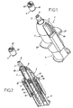
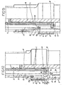
- FIGS. 1 to 8 show a nasal spray device 1, according to a first embodiment of the invention, making it possible to deliver two determined doses of a product of interest in liquid form, one for each nostril.
- This device 1 comprises a syringe body 2, a spray tip 3, a piston 4, a pusher 5, a case 6 and a protective cap 7.
- the syringe body 2 is of conventional type, for example glass, with a proximal flange 10 and a distal flow duct 80.
- the tip 3 is fitted on the distal end of the syringe body 2. It forms a spray head 11 for spraying the product contained in the syringe body 2, and comprises a proximal collar 12. Such a tip 3 being known in itself, it is not described in more detail.
- the piston 4 is also of conventional type, being a syringe piston.
- the pusher 5 has a generally hollow cylindrical shape, closed by a proximal bottom 15, and comprises an axial rod 16 integral with this bottom 15, receiving the piston 4 at its distal end by means of a nipple 16a that she understands.
- the wall 83 of the pusher 5 is stiffened by internal ribs, longitudinal, 81 and 82, parallel to the rod 16.
- the pusher 5 also comprises, in the example shown, four grooves 84, 85 arranged longitudinally from its distal end, defining two movable tabs 17 diametrically opposite.
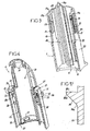
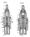
- the entire pusher 5 is made of a common plastic material, slightly flexible, the radial or tangential mobility of the tabs 17 resulting from the flexibility of this material. This flexibility allows the mobility of the tabs 17 between a first radial position, unstressed, internal, non-deformation, shown in Figures 2, 3, 5, 7 and 8, and a second radial position bent, external, under stress, shown in Figure 6, wherein these tabs 17 are elastically deformed.
- Each lug 17 has a distal head or bearing zone 17a, with projecting edges 17b, forming, with a complementary means that includes the case 6, namely a boss 38 in the example shown, latching means allowing prevent the separation of the pusher 5 and the case 6, after the engagement of the pusher in the case, as will appear below.
- the tabs 17 further comprise two pairs of pins 20, 21 projecting laterally, respectively located on the one and the other tab at two different heights respectively. These lugs 20, 21 define, with the corresponding bosses 38 arranged on the case 6, "hard spots" to be crossed at the beginning of spraying a dose, as will also be explained later.
- Each lug 17 also comprises a window or zone of non-support 22 arranged through it, set back from a bearing zone 17a; this window extends axially over a predetermined length.
- the case 6 comprises two walls 25, 26 joining at the distal end of this case, these walls 25, 26 delimiting between them a space 27 in which the pusher 5 is intended to be engaged in sliding.
- the inner wall 25 delimits a housing 30 for receiving and axially fixing the syringe body 2 and the spray tip 3, the case 6 comprising distal tabs 31 which make it possible to center the tip 3 and the distal end. of the syringe body 2, as well as proximal projections 32 for snapping the collar 10 of the syringe body 2.
- This inner wall 25 also comprises, in the example shown, two projections 33 each comprising an oblique ramp, facing the distal end of the device 1, diametrically opposed, projecting from its outer face, these projections 33 being intended to cooperate with the legs 17 of the pusher 5, as will appear below. These projections also have a shape adapted to freely penetrate and slide inside a window 22, as described below.
- the ramps 86 have front edges 86c (those facing the tabs 17), rounded, and are shaped so as to be met by the tabs 17 only at the end of the spray or at the end. injection of the first dose. This avoids the generation of friction at the beginning of spraying or injection of the first dose, when the speed of the pusher is low
- the outer wall 26 comprises two returns 35 forming, within said space 27 and at a determined distance from the projections 33, internal stops 36 against which the distal heads 17a of the tabs 17 can respectively abut, as will also be explained further.
- These returns 35 also include two openings 37 which allow the passage in axial translation of the legs 17 to slide through them.
- the outer wall 26 further comprises the two internal bosses 38, beyond which the heads 17a of the tabs 17 snap, by their projecting edges 17b, to prevent the separation of the pusher 5 and the case 6, and with which cooperate the lugs 20, 21 to form the aforementioned hard points.
- the outer wall 26 also comprises, in the example shown, two diametrically opposite outer tabs 40 projecting from its outer face, serving to support two fingers of the user for the exercise on the case 6 of a effort, antagonistic to the thrust exerted on the bottom of the pusher 5 by another finger of the user.
- the cap 7 has meanwhile a transverse end wall 45 and a peripheral wall 46 enabling it to wrap the part of the tip 3 protruding from the case 6.
- Figure 5 shows the device 1 at the beginning of the spraying phase of a first dose of product. Counteracting forces are exerted on the pusher 5 and on the outer tabs 40 to cause the aforementioned pin 20 of a tab 17 to cross the corresponding boss 38, then to slide the pusher 5 relative to the case 6, realizing thus spraying the first dose.
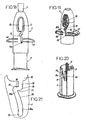
- the heads or support zones 17a of the tabs 17 meet the ramps 86 of the projections 33, respectively, which moves these tabs 17 towards their second radially external positions, by sliding the heads 17a, each of a so-called initial end 86a, at a so-called final end 86b of a ramp 86; cf. figure 17.
- a new thrust can then be exerted on the pusher 5, with an antagonistic force on the external tabs 40, to start the spraying of the second dose.
- the lug 21 is then just below the corresponding boss 38, so that there is a second hard point to be crossed to start this second spraying. Once this hard point is crossed, the second spraying can take place, the tabs 17 sliding through the openings 37, and the projections 33 sliding through the windows 22, to the end of spray position shown in FIG. 8.
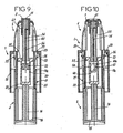
- Figures 9 and 10 show a device 1 very similar to that just described
- the elements already described with reference to Figures 1 to 8, functionally identical or equivalent, which are found in this device, are designated by the same reference numerals and will not be described again.
- the device 1 comprises a receptacle 50 of carpule type, with a proximal bottom 51 and with a distal flange 52, a piston 53 with a thinned central zone, a hollow needle 54 capable of piercing this thinned central zone, and a rod 55 held by a spray tip 3 mounted on the case 6, the rod 55 having the needle 54 and forming a conduit 56 of the product flow.
- the central rod 16 of the pusher 5 bears against the bottom 51 of the container 50, which moves the container 50 and the piston 53 until the needle 54 pierces the thinned central zone of the piston 53, thus allowing the flow of the liquid product of interest.
- the device 1 comprises a receptacle 50 identical to that of the device shown in FIG. 9, and a rod 55 similar to that which this device comprises, but devoid of a needle 54.
- the piston 60 then comprises an axial recess 61, opening into its distal face and arranged on one side of this piston 60, this recess 61 thus delimiting a side wall portion 60a of the piston 60 having a flexibility in the direction radial of this piston.
- This wall 60a is erased under the pressure of the product resulting from the support of the rod 55 against the piston 60, following the displacement of the container 50 relative to the rod 55, thus releasing the flow of the product.
- FIG. 11 shows a device 1 similar to that described with reference to FIGS. 1 to 8, according to a second embodiment of the invention.
- the tabs 17 are arranged on the case 6, and the projections 33 and the stops 36 are arranged on the pusher 5.
- the structural elements, and / or functionally identical or equivalent, already described with reference to FIGS. 1 to 8 , which are found in this device, are designated by the same reference numerals and are not described again.
- the tabs 17 are formed by grooves arranged on either side in said inner wall 25.
- FIG. 16 shows a device 1 similar to the first embodiment of the invention, except that it comprises a cap 7 connected to the case 6 by ruptible bridges 80. These bridges 80 make it possible to force the user to have a voluntary action of use and to avoid that this use is too easy for children.
- the tabs 17 are arranged on the pusher 5, while the ramp 86 is disposed on the case 6, in the form of a continuous groove passing through the wall of said case.
- the opening 22 of non-support, belonging to the through groove, is disposed on the case 6, below the abutment 36, also belonging to said through groove, when the lug 17 is disposed on the pusher 5 (as already indicated ), and the support element 17a specified below cooperates with the recessed ramp 86, formed on the case 6.
- the abutment 36 which has been mentioned in the previous embodiments of the invention cooperates with the stud 17a, it is disposed on the case 6 beyond the end end 86b of the ramp 86, and is determined by the junction at an angle, but continuous of the ramp 86 with a ramp return 90, inverted slope relative to the ramp 86 itself.
- the zone or opening of no support 22, which has been mentioned previously, is disposed recessed on the case 6, below the abutment 36 previously defined, in continuity with the ramp 86 and the ramp return 90; this area 22 of non-support is adapted to accommodate the stud 17a, when the tab 17 returns to its normal position, from its stopped position and flexed.
- an axial slot 91 extends continuously from the non-support zone 22 described above, but beyond the latter.
- the axial slot 91 in the case 6 opens freely into a through opening 92 of the case 6, forming a window through the outer wall of said case; it being understood that according to this third form embodiment of the invention, the second stroke portion of the pusher 5 is determined by the abutment of the piston against the wall of the container 2.
- a parking slot 93 of the stud 17 is provided below the initial end 86a of the ramp 86, and in continuity with the latter.
- the snap of the pin 17a in the housing 93 allows the final assembly of the pusher 5 and the case 6.
- a parking slot 94 of the stud 17a is formed, as for the housing 93, in the outer wall of the case 6.
- the third embodiment of the invention provides greater robustness and a smaller axial dimension. This embodiment also ensures an effective stop of the pusher relative to the case between the two portions of the stroke of said pusher, therefore before the second dose of the product of interest is delivered.
- a fourth and final embodiment of the present invention is described which is similar to the first or second embodiment previously described.
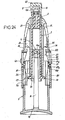
- the ramp 86 and the free end 87a of the tongue 87 are adapted to cooperate with each other, so that during the first stroke portion of the pusher, for example at the end of the latter, the tab 87 is flexed (confer Figure 27), and during the second portion of the pusher stroke, the tab 87 escapes the ramp 86 and returns to its position normal (see Figures 29 and 30).
- the first normal, unconstrained position of the tongue 87 is shown in FIG. that a second flexed position, under stress, is shown in Figures 26 to 28.
- Each tab 17, disposed as appropriate on the pusher 5 or the case 6, comprises a window 22 of generally rectangular shape, non-support, in the center of which extends the tongue 87 parallel to the axis of the device .
- the ramp 86 is part of a protrusion 33 arranged according to the case on the case 6 or the pusher 5, which is adapted to pass freely through the window 22.
- the stop 36 is arranged, on the case 6 or the pusher 5, as the case may be, so that in the second flexed position of each lug 17, the projection 33 comes opposite the window 22, then penetrates through the latter, when the thrust on the pusher 5 is released, causing the return of each lug 17 in its first position.
- each tab 87 is disposed in the center of the window 22, with its free end 87a remaining below the head 17a or support zone of the corresponding tab.
- the free end 87a comprises two lugs 88 bearing against the ramp 86.
- the latter comprises two parallel wings 331 and 332, disposed on either side of a slot 89, which allows the free passage in translation of the tongue 87.
- Each ear 88 is arranged to come into contact with a ramp portion 86 defined by a wing 331 or 332, in the direction of the thrust of the pusher 5; beyond the first stroke portion of the pusher 5, each ear 88 escapes the ramp portion or wings 331 or 332, corresponding, so that the tongue 87 returns to normal position.
Landscapes
- Health & Medical Sciences (AREA)
- Engineering & Computer Science (AREA)
- Life Sciences & Earth Sciences (AREA)
- Public Health (AREA)
- Heart & Thoracic Surgery (AREA)
- Hematology (AREA)
- Anesthesiology (AREA)
- Animal Behavior & Ethology (AREA)
- General Health & Medical Sciences (AREA)
- Veterinary Medicine (AREA)
- Biomedical Technology (AREA)
- Bioinformatics & Cheminformatics (AREA)
- Pulmonology (AREA)
- Otolaryngology (AREA)
- Mechanical Engineering (AREA)
- Biophysics (AREA)
- Vascular Medicine (AREA)
- Infusion, Injection, And Reservoir Apparatuses (AREA)
- Containers And Packaging Bodies Having A Special Means To Remove Contents (AREA)
- Acyclic And Carbocyclic Compounds In Medicinal Compositions (AREA)
- Medicines That Contain Protein Lipid Enzymes And Other Medicines (AREA)
- Nozzles (AREA)
Claims (25)
- Sprüh- oder Injektionsvorrichtung (1) zur Abgabe mindestens zweier vorbestimmter Dosen eines Produkts, welche Folgendes aufweist:- ein Behältnis (2, 50), welches das zu versprühende oder zu injizierende Produkt enthält,- einen Kolben (4, 53, 60), welcher in dem Behältnis (2, 50) angeordnet und in dem Behältnis (2, 50) verschiebbar ist, um das Produkt aus dem Behältnis (2, 50) herauszudrücken,- eine Hülle (6), in welcher das Behältnis (2, 50) angeordnet ist,- einen Stößel (5), welcher im Verhältnis zur Hülle (6) verschiebbar ist, um eine Verschiebung relativ zum Behältnis (2, 50) und zum Kolben (4, 53, 60) zu ermöglichen, sowie- Mittel (17, 33, 36, 37), durch welche der Verlauf der Verschiebung des Stößels (5) im Verhältnis zur Hülle (6) in zumindest zwei Teilverlaufe unterteilt werden kann, welche jeweils der Abgabe einer Dosis des Produkts entsprechen;
wobei die Vorrichtung (1) dadurch gekennzeichnet ist, dass- die Hülle (6) oder der Stößel (5) zumindest eine Lasche (17) aufweisen, welche zwischen einer ersten radialen normalen Position, in welcher die Lasche (17) die Verschiebung des Stößels (5) im Verhältnis zur Hülle (6) nicht blockieren kann, und einer zweiten radialen Position radial beweglich ist, in welcher die Lasche (17) diese Verschiebung blockieren kann, wobei die Lasche (17) einen aufliegenden Bereich (17a) und einen nicht-aufliegenden Bereich (22) aufweist;- der Stößel (5) oder die Hülle (6) jeweils zumindest einen Vorsprung (33) in Form einer Schräge umfassen, gegen welche der aufliegende Bereich (17a) der Lasche (17) stößt, und zwar im Verlauf der Verschiebung des Stößels (5) im Verhältnis zur Hülle (6) in die Richtung, welche das Versprühen oder Injizieren des Produktes ermöglicht, was die Lasche (17) in eine zweite radiale Position führt, gegenüber welcher dann der aufliegende Bereich (22) der Lasche (17) zu liegen kommt, was das Zurückführen der Lasche (17) in die erste radiale Position ermöglicht; der Stößel (5) oder die Hülle (6) umfassen jeweils zumindest einen Anschlagsbereich (36), gegen welchen die Lasche (17) in Auflage kommt, wenn sie über den Vorsprung (33) in die zweite radiale Position geführt wird, wobei die Auflage, die genau vor dem Vorsprung (33) erscheint, gegenüber der nicht-aufliegenden Zone (22) zu liegen kommt,- die Vorrichtung (1) derart ausgebildet ist, dass das Nachlassen der auf den Stößel (5) ausgeübten Kraft, welche die Verschiebung des Stößels (5) im Verhältnis zur Hülle (6) ermöglicht, die Freisetzung der Auflage der Lasche (17) gegen den Anschlagsbereich (36) ermöglicht, und daher das Rückführen der Lasche (17) in die erste radiale Position ermöglicht, wobei der Vorsprung (33) dann gegenüber dem Bereich, der nicht aufliegt (22), zu liegen kommt, und wobei diese Rückführung der Lasche (17) in die erste radiale Position es ermöglicht, die Verschiebung des Stößels (5) für einen Teilverlauf der folgenden Verschiebung freizugeben, im Hinblick auf das Versprühen oder die Injizierung einer folgenden Dosis des Produkts. - Vorrichtung (1) nach Anspruch 1, dadurch gekennzeichnet, dass der nicht aufliegende Bereich der Lasche (17) durch ein Fenster (22) gebildet ist, welches in der Lasche (17) ausgebildet ist, und vom Kopfende dieser Lasche zurückgesetzt ist, und wobei der aufliegende Bereich durch einen Bereich (17a) dieser Lasche gebildet wird, welcher das Kopfende der Lasche und das Fenster (22) miteinander verbindet.
- Vorrichtung (1) nach Anspruch 1 oder Anspruch 2, dadurch gekennzeichnet, dass sie zumindest zwei Laschen (17), zwei Vorsprünge (33) und zwei Anschlagbereiche (36) umfasst, welche einander diametral gegenüberliegen.
- Vorrichtung (1) nach einem der Ansprüche 1 bis 3, dadurch gekennzeichnet, dass die Hülle (6) und der Stößel (5) Mittel (20, 21, 38) umfassen, welche die Bildung von zumindest einem "harten Punkt" ermöglichen, der überwunden werden muss, um mit der Abgabe einer Dosis beginnen zu können.
- Vorrichtung (1) nach Anspruch 4, dadurch gekennzeichnet, dass die Mittel, welche die Bildung von zumindest einem "harten Punkt" ermöglichen, aus zumindest einer Noppe (20, 21), welche den seitlichen Vorsprung der oben genannten Lasche (17) ausmacht, und aus zumindest einer Erhebung (38) besteht welche einer passenden, der Hülle (6) entsprechenden Stelle zugeführt wird.
- Vorrichtung (1) nach einem der Ansprüche 1 bis 5, dadurch gekennzeichnet, dass der Stößel (5) in seiner Gesamtheit aus einem harten, leicht flexiblen Plastikmaterial hergestellt ist, und dass die Beweglichkeit jeder Lasche (17) von der Flexibilität des Materials herrührt, wobei jede Lasche (17) in der ersten radialen Position nicht verformt ist und in der zweiten radialen Position elastisch eingebogen ist.
- Vorrichtung (1) nach einem der Ansprüche 1 bis 6, dadurch gekennzeichnet, dass jede Lasche (17) einen distalen Kopf (17a) mit vorspringenden Rändern aufweist, welche mit einem von der Hülle (6) umfassten komplementären Mittel Einrastmittel bilden, die die Trennung des Stößels (5) und der Hülle (6) nach dem Eingriff des Stößels in die Hülle verhindern können.
- Vorrichtung (1) nach einem der Ansprüche 1 bis 7, dadurch gekennzeichnet, dass die Hülle (6) zwei Wände (25, 26) aufweist, welche zwischen einander einen Raum (27) begrenzen, in welchen der Stößel (5) verschiebbar eingreifen soll, wobei jeweils der Vorsprung (33) von der äußeren Fläche der Innenwand (25) vorsteht, und die Außenwand (26) zumindest einen Rückhalt (35) aufweist, welcher - im Inneren des Raumes (27) und in einem bestimmten Abstand von dem Vorsprung (33) - den Anschlagbereich (36) bildet, wobei jeder Rückhalt (35) darüber hinaus eine Öffnung (37) aufweist, welche das Durchführen der zu verschiebenden Lasche (17) durch diese hindurch ermöglicht.
- Vorrichtung (1) nach einem der Ansprüche 1 bis 7, dadurch gekennzeichnet, dass die Hülle (6) zwei Wände (25, 26) aufweist, welche zwischen einander einen Raum (27) begrenzen, in welchen der Stößel (5) verschiebbar eingreifen soll, wobei der Stößel (5) eine Innenwand (70) aufweist, in welcher jeweils der Anschlagbereich (36) vorgesehen ist, und eine äußere Wand (71), welche jeweils den Vorsprung (33) umfasst, wobei die Außenwand (71) sich jeweils über den Vorsprung (33) hinweg erstreckt und in den Raum (27) eingreift, wobei die Innen- (70) und die Außenwand (71) des Stößels zwischen sich jeweils eine Öffnung (37) begrenzen, und wobei die Lasche (17) jeweils in der Innenwand (25) der Hülle (6) vorgesehen ist.
- Vorrichtung (1) nach einem der Ansprüche 1 bis 9, dadurch gekennzeichnet, dass das Behältnis durch einen Spritzenkörper (2) gebildet ist, welcher einen proximalen Flansch (10) und eine distale Abflussleitung aufweist, wobei der Spritzenkörper (2) ein Endstück zum Versprühen (3) aufweist, welches auf dessen distalem Ende aufgesteckt ist, welches einen Sprühkopf (11) bildet, welcher das Versprühen des Produkts, das in dem Spritzenkörper (2) enthalten ist, ermöglicht.
- Vorrichtung (1) nach einem der Ansprüche 1 bis 9, dadurch gekennzeichnet, dass sie ein Behältnis (50) mit einem proximalen Boden (51) aufweist, ferner einen Kolben (53) mit einem mittigen, sich verjüngenden Bereich, eine Hohlnadel (54) zum Durchstechen dieses mittigen, sich verjüngenden Bereichs, und ferner einen Schaft (55), der in der Hülle (6) gehalten wird, wobei dieser Schaft (55) die Nadel (54) umfasst und eine Abflussleitung (56) für das Produkt bildet.
- Vorrichtung (1) nach einem der Ansprüche 1 bis 9, dadurch gekennzeichnet, dass sie ein Behältnis (50) mit einem proximalen Boden (51) aufweist, ferner einen Kolben (60), welcher eine axiale Aussparung (61) aufweist, die in die distale Fläche des Kolbens (60) einmündet und die auf einer Seite des Kolbens (60) vorgesehen ist, wobei diese Aussparung (61) auf diese Weise einen Teil einer Seitenwand (60a) dieses Kolbens (60) umgrenzt, welcher in radiale Richtung des Kolbens biegsam ist, und einen Schaft (55), der in der Hülle (6) gehalten wird, welcher eine Abflussleitung (56) für das Produkt bildet, wobei dieser Schaft (55) dazu geeignet ist, gegen den Kolben (60) zu drücken, und zwar im Verlauf der Verschiebung des Stößels (5) im Verhältnis zur Hülle (6).
- Vorrichtung (1) zum Versprühen oder Injizieren eines Produkts von Interesse in flüssiger Form, mit welcher zumindest eine vorbestimmte erste Dosis und eine vorbestimmte zweite Dosis des Produkts schrittweise abgegeben werden kann, wobei die Vorrichtung sich entlang einer Referenzachse von einem distalen Ende bis zu einem proximalen Ende erstreckt, und wobei sie Folgendes aufweist:- ein sich axial erstreckendes Behältnis (2, 50), welches das Produkt enthält,- einen Kolben (4, 53, 60), welcher in dem Behältnis vorliegt und welcher Letzteres verschließen kann, wobei der Kolben im Verhältnis zum Behältnis in Referenzrichtung axial verschiebbar ist, wodurch das Produkt distal aus dem Behältnis ausgetrieben werden kann,- eine Hülle (6), welche zur Aufnahme und zur axialen Fixierung des Behältnisses angeordnet ist,- einen mit einer Hülle (6) zusammengesetzten Stößel (5), der verschiebbar im Verhältnis zu Letzterem ist, und welcher derart angeordnet ist, dass er in axialen und proximalen Anschlag gegen das Behältnis oder den Kolben kommt, und dass er den Kolben in die Referenzrichtung verschiebt,- Mittel (17, 33, 36, 37) zur Steuerung des Verschiebungsverlaufes des Stößels im Verhältnis zur Hülle, welche Mittel zur Aufteilung dieser Letzteren in einen ersten und einen zweiten Verlaufsteil angeordnet sind, durch welche die jeweilige Abgabe der ersten und zweiten Dosen bestimmt wird, wobei die Vorrichtung durch eine Hülle (6) und einen Stößel (5) charakterisiert ist, welche derart angeordnet sind, dass sie axial im Verhältnis zueinander in Richtung des Schubes verschiebbar sind, wodurch der Kolben in die Referenzrichtung verschoben wird, und
dadurch, dass die Mittel zur Steuerung Folgendes aufweisen:- zumindest eine Lasche (17), die an dem Stößel (5) oder der Hülle (6) angebracht ist, und die zwischen einer ersten normalen, unbelasteten Position, in welcher die Lasche die axiale Verschiebung des Stößels nicht blockieren kann, und einer zweiten gebogenen erzwungenen Position beweglich ist, in welcher die Lasche die axiale Verschiebung des Stößels blockiert, wobei die Lasche an ihrem freien Ende einen Auflagebereich oder ein Auflageelement (17a) aufweist, welches dazu vorgesehen ist, gleichzeitig für den Stopp der axialen Verschiebung des Stößels (5) und für die Biegung der Lasche (17) zu sorgen, mit dem Effekt, dass der Stößel axial verschoben wird,- zumindest eine Schräge (86), welche mit der Lasche von einem Anfangsende (86a) bis zu einem Schlussende (86b) zusammenwirkt, und welche jeweils an der Hülle (6) oder dem Stößel (5) angebracht ist, und gegen welche der Auflagebereich oder das Auflageelement (17a) der Lasche (17) aufsitzt, und zwar in Richtung des Schubes des Stößels (5), wobei die Schräge dazu vorgesehen ist, die Lasche von deren ersten normalen Position in deren zweite gebogene Position zu führen,- zumindest einen Anschlag (36), der mit dem Auflagebereich oder dem Auflageelement (17a) der Lasche (17) zusammenwirkt, und der jeweils auf der Hülle (6) oder dem Stößel (5) angebracht ist, und zwar in Schubrichtung jeweils über oder unter das Schlussende (86b) der Schräge (86) hinweg, gegen welche der Auflagebereich oder das Auflageelement (17a) der Lasche (17) schließlich in deren zweiten gebogenen Position in Kontakt kommt,- zumindest einen nicht aufliegenden Bereich oder Öffnung (22), welcher - wenn er auf der Lasche (17) vorgesehen ist - unter oder über dem Auflagenbereich oder das Auflagenelement (17a) hinweg angebracht ist, je nachdem die Lasche auf dem Stößel (5) oder der Hülle (6) vorgesehen ist, oder welcher,- wenn er an der Hülle (6) vorgesehen ist - unter dem Anschlag (36) vorgesehen ist, wenn die Lasche (17) an dem Stößel (5) vorgesehen ist und das Auflageelement (17a) mit einer versenkten Schräge (86) zusammenwirkt, welche an der Hülle angebracht ist, wobei der nicht aufliegende Bereich oder Öffnung (22) dazu vorgesehen ist, den Rückhalt des Auflagenbereichs oder des Auflagenelements (17a) zu ermöglichen, und zwar bis zu dessen normalen, unbelasteten Position, ausgehend von der festgesetzten und gebogenen Position der Lasche (17), wenn der Schub auf den Stößel (5) nachlässt,- einen ersten Verlaufsteil des Stößels (5), welcher für die Verschiebung des Letzteren bis zu dessen festgestellten axialen Position bestimmt ist, gefolgt von dem Kontakt des Auflagenbereichs oder des Auflagenelements (17a) mit dem Anschlag (36), und einem zweiten Verlaufsteil für die Verschiebung des Stößels über die axiale Position hinweg, in welcher der nicht aufliegende Bereich oder Öffnung (22) den Auflagenbereich oder das Auflagenelement (17a) aufgenommen hat. - Vorrichtung nach Anspruch 13, dadurch gekennzeichnet, dass die zweite gebogene Position der Lasche durch einen radialen Druck erzeugt wird.
- Vorrichtung nach Anspruch 14, dadurch gekennzeichnet, dass die Lasche (17), welche an dem Stößel (5) oder der Hülle (6) vorgesehen ist, ein nicht aufliegendes Fenster (22) aufweist, welches im Verhältnis zum Auflagebereich oder dem Auflageelement (17a) zurücktritt; dass ferner die Schräge (86) zu einem Vorsprung (33) gehört, der jeweils an der Hülle (6) oder dem Stößel (5) vorgesehen ist, und dazu ausgebildet ist, durch das Fenster (22) frei hindurch zu dringen; dass ferner der Anschlag (36) derart eingerichtet ist, dass - in der zweiten gebogenen Position der Lasche - der Vorsprung (33) gegenüber dem Fenster (22) der Lasche zu liegen kommt, und danach mitten durch das Fenster dringt, wenn der Schub auf den Stößel (5) freigegeben wird, was den Rückzug der Lasche in deren erste Position bewirkt.
- Vorrichtung nach Anspruch 13, dadurch gekennzeichnet, dass die zweite gebogene Position der Lasche durch tangentialen Druck erzeugt wird.
- Vorrichtung nach Anspruch 16, dadurch gekennzeichnet, dass die Lasche (17) an dem Stößel (5) vorgesehen ist, der an seinem freiem Ende eine Ansatzkappe (17a) mit Querausdehnung gegen die Hülle (6) aufweist, eine vordere Fuge (84, 85) an der Lasche, welche deren tangentialen Spielraum von deren ersten normalen Position in deren zweite gebogene Position ermöglicht, dass ferner eine versenkte Schräge (86) an der Hülle (6) zur Aufnahme des Stößels (17a) vorgesehen ist, die sich vom Anfangsende (86a) bis zum Schlussende (86b) merklich schrägwinklig in der Wand der Hülle erstreckt; dass der Anschlag, der mit der Ansatzkappe (17a) zusammenarbeitet, an der Hülle über das Schlussende (86b) der Schräge (86) hinweg vorgesehen ist und welcher für eine winklige, aber kontinuierliche Verbindung der Schräge (86) mit einem Rückhalt der Schräge (90) bestimmt ist; dass der nicht aufliegende Bereich oder Öffnung (22), welcher an der Hülle (6) unter dem Anschlag (36) versenkt angebracht ist, zur Aufnahme der Ansatzkappe (17a) angepasst ist, wenn die Lasche (17) in ihre normale Position zurückkehrt; und dass sich ein axialer Schlitz (91) kontinuierlich über den nicht aufliegenden Bereich über den Letzteren hinweg erstreckt.
- Vorrichtung nach Anspruch 17, dadurch gekennzeichnet, dass der axiale Schlitz (91) in eine durchgehende Öffnung (92) der Hülle (6) mündet, wobei der zweite Verlaufsteil des Stößels (5) zum Anschlag des Kolbens (4) gegen die Wand des Behältnisses (2) bestimmt ist.
- Vorrichtung nach Anspruch 17, dadurch gekennzeichnet, dass unter dem Anfangsende (86a) der Schräge (86) - und kontinuierlich mit der Letzteren - eine Halteaufnahme für die Ansatzkappe (17a) vorgesehen ist, insbesondere um eine endgültige Verbindung des Stößels (5) und der Hülle (6) zu ermöglichen.
- Vorrichtung nach Anspruch 17, dadurch gekennzeichnet, dass über den nicht aufliegenden Bereich oder Öffnung (22) hinaus - und kontinuierlich mit Letzterem - eine Halteaufnahme (94) für die Ansatzkappe (17a) vorgesehen ist.
- Vorrichtung nach Anspruch 13, dadurch gekennzeichnet, dass der eine Teil zumindest eine Zunge (87) aufweist, welche getrennt oder unabhängig von der Lasche (17) ist, und welche an dem Stößel (5) oder der Hülle (6) angebracht ist, wonach die Lasche (17) an dem Stößel (5) oder der Hülle (6) angebracht ist, und zwar beweglich zwischen einer ersten normalen, nicht belasteten Position, in welcher die Zunge die axiale Verschiebung des Stößels (5) nicht blockiert, und einer zweiten gebogenen, belasteten Position, in welcher die Zunge (87) zu der Rückstellung des Stößels (5) beiträgt, um die Rückführung der Lasche (17), ausgehend von deren festgestellten und gebogenen Position, in deren normale Position zu ermöglichen, und dass der andere Teil, nämlich die Schräge (86) und das freie Ende (87a) der Zunge (87) zur Zusammenwirkung des einen mit dem anderen ausgebildet sind, und zwar derart, dass - während des ersten Teilverlaufs des Stößels - sich die Zunge im gebogenen Zustand befindet, und dass die Zunge (87) - während des zweiten Teilverlaufs des Stößels - von der Schräge freikommt und in ihre normale Position zurückkehrt.
- Vorrichtung nach Anspruch 21, dadurch gekennzeichnet, dass die zweite gebogene Position der Zunge (87) durch radialen Druck erzeugt wird, wenn die zweite gebogene Position der Lasche (17) durch radialen Druck erzeugt wird.
- Vorrichtung nach Anspruch 21, dadurch gekennzeichnet, dass die zweite gebogene Position der Zunge (87) durch tangentialen Druck erzeugt wird, wenn die zweite gebogene Position der Lasche (17) durch tangentialen Druck erzeugt wird.
- Vorrichtung nach Anspruch 22, dadurch gekennzeichnet, dass die Lasche (17), die an dem Stößel (5) oder der Hülle (6) angebracht ist, ein nicht aufliegendes Fenster (22) umfasst, dass die Schräge (86) zu einem Vorsprung (33) gehört, welcher jeweils an der Hülle (6) oder dem Stößel (5) angebracht ist, und zum freien Durchdringen des Fensters (22) angepasst ist; ferner, dass der Anschlag (36) derart ausgebildet ist, dass - in der zweiten gebogenen Position der Lasche - der Vorsprung (33) gegenüber dem Fenster (22) der Lasche zu liegen kommt und dann mittendurch das Fenster hindurchreicht, wenn der Schub des Stößels (5) gelockert wird, was den Rückzug der Lasche in ihre erste Position bewirkt.
- Vorrichtung nach Anspruch 24, dadurch gekennzeichnet, dass die Zunge (87) in der Mitte des Fensters (22) vorgesehen ist, dass das freie Ende (87a) der Zunge (87) sich unter dem Kopf (17a) befindet und zwei Ohren (88) zum Aufliegen gegen die Schräge (86) aufweist, und andererseits die Schräge (90) zwei Flügel (331) und (332) aufweist, die zu beiden Seiten eines Schlitzes (89) angebracht sind, um den freien Übertragungsdurchgang der Zunge zu ermöglichen, wobei jedes Ohr (88) in Schubrichtung des Stößels (5) mit einem Teil der Schräge (86) in Kontakt kommt, welcher als Flügel (331, 332) definiert ist, um über den ersten Verlaufsteil des Stößels (5) hinweg aus dem Teil der Schräge hinauszugelangen.
Applications Claiming Priority (3)
| Application Number | Priority Date | Filing Date | Title |
|---|---|---|---|
| FR0212002 | 2002-09-27 | ||
| FR0212002A FR2845016B1 (fr) | 2002-09-27 | 2002-09-27 | Dispositif de pulverisation ou d'injection permettant de delivrer au moins deux doses determinees de produit |
| PCT/FR2003/002836 WO2004028703A2 (fr) | 2002-09-27 | 2003-09-26 | Dispositif de pulverisation ou d'injection permettant de delivrer au moins deux doses determinees de produit |
Publications (2)
| Publication Number | Publication Date |
|---|---|
| EP1542807A2 EP1542807A2 (de) | 2005-06-22 |
| EP1542807B1 true EP1542807B1 (de) | 2006-02-22 |
Family
ID=31985297
Family Applications (1)
| Application Number | Title | Priority Date | Filing Date |
|---|---|---|---|
| EP03776944A Expired - Lifetime EP1542807B1 (de) | 2002-09-27 | 2003-09-26 | Sprüh- oder injektionsvorrichtung zur dosierten abgabe mindestens zweier dosen eines produkts |
Country Status (9)
| Country | Link |
|---|---|
| US (2) | US7681570B2 (de) |
| EP (1) | EP1542807B1 (de) |
| JP (1) | JP4509786B2 (de) |
| AT (1) | ATE318185T1 (de) |
| AU (1) | AU2003286203A1 (de) |
| DE (1) | DE60303681T2 (de) |
| ES (1) | ES2256787T3 (de) |
| FR (1) | FR2845016B1 (de) |
| WO (1) | WO2004028703A2 (de) |
Families Citing this family (41)
| Publication number | Priority date | Publication date | Assignee | Title |
|---|---|---|---|---|
| EP1092447B1 (de) * | 1999-10-14 | 2004-01-07 | Becton Dickinson and Company | Nasales Verabreichungsgerät mit Zerstäuberdüse |
| FR2845016B1 (fr) * | 2002-09-27 | 2004-12-03 | Becton Dickinson France | Dispositif de pulverisation ou d'injection permettant de delivrer au moins deux doses determinees de produit |
| US7947017B2 (en) | 2004-11-22 | 2011-05-24 | Intelliject, Inc. | Devices, systems and methods for medicament delivery |
| US11590286B2 (en) | 2004-11-22 | 2023-02-28 | Kaleo, Inc. | Devices, systems and methods for medicament delivery |
| US10737028B2 (en) | 2004-11-22 | 2020-08-11 | Kaleo, Inc. | Devices, systems and methods for medicament delivery |
| US7648483B2 (en) | 2004-11-22 | 2010-01-19 | Intelliject, Inc. | Devices, systems and methods for medicament delivery |
| EP1814611A4 (de) | 2004-11-22 | 2010-06-02 | Intelliject Inc | Vorrichtungen, systeme und verfahren zur abgabe eines medikaments |
| GB2451769B (en) | 2005-02-01 | 2009-12-09 | Intelliject Llc | Devices, systems, and methods for medicament delivery |
| FR2908753B1 (fr) * | 2006-11-16 | 2011-11-11 | Becton Dickinson France | Dispositif pour delivrer automatiquement des doses successives de produit |
| WO2010033882A2 (en) * | 2008-09-18 | 2010-03-25 | Becton, Dickinson And Company | Medical injector with slidable sleeve activation |
| US9250106B2 (en) | 2009-02-27 | 2016-02-02 | Tandem Diabetes Care, Inc. | Methods and devices for determination of flow reservoir volume |
| US8573027B2 (en) | 2009-02-27 | 2013-11-05 | Tandem Diabetes Care, Inc. | Methods and devices for determination of flow reservoir volume |
| JP5439037B2 (ja) * | 2009-05-29 | 2014-03-12 | 株式会社吉野工業所 | 吐出容器 |
| US8926561B2 (en) | 2009-07-30 | 2015-01-06 | Tandem Diabetes Care, Inc. | Infusion pump system with disposable cartridge having pressure venting and pressure feedback |
| WO2011079278A1 (en) | 2009-12-23 | 2011-06-30 | Becton, Dickinson And Company | Monodose nasal drug delivery device |
| CA2779692A1 (en) * | 2010-02-26 | 2011-09-01 | Byung Eun Yoo | Portable enema device |
| US20140283820A1 (en) * | 2010-07-01 | 2014-09-25 | Medinvent, Llc | Method for Esophageal Drug Delivery |
| US8627816B2 (en) | 2011-02-28 | 2014-01-14 | Intelliject, Inc. | Medicament delivery device for administration of opioid antagonists including formulations for naloxone |
| US8939943B2 (en) | 2011-01-26 | 2015-01-27 | Kaleo, Inc. | Medicament delivery device for administration of opioid antagonists including formulations for naloxone |
| US9345866B2 (en) * | 2011-05-13 | 2016-05-24 | Nipro Corporation | Nasal cavity administration container |
| US10682331B2 (en) | 2012-02-24 | 2020-06-16 | Nasoneb, Inc. | Nasal drug delivery and method of making same |
| CA2869155C (en) * | 2012-03-30 | 2017-01-31 | Yoshino Kogyosho Co., Ltd. | Metered quantity syringe-type dispenser |
| US9180242B2 (en) | 2012-05-17 | 2015-11-10 | Tandem Diabetes Care, Inc. | Methods and devices for multiple fluid transfer |
| US9968743B2 (en) * | 2012-11-30 | 2018-05-15 | Yoshino Kogyosho Co., Ltd. | Quantitative syringe-type ejector |
| TR201707036T4 (en) | 2012-12-04 | 2018-11-21 | Ino Therapeutics Llc | Cannula to minimize dose dilution during administration of nitric oxide |
| US9795756B2 (en) | 2012-12-04 | 2017-10-24 | Mallinckrodt Hospital Products IP Limited | Cannula for minimizing dilution of dosing during nitric oxide delivery |
| JP2014140588A (ja) * | 2013-01-25 | 2014-08-07 | Shinko Chemical Co Ltd | 噴霧容器 |
| US9173998B2 (en) | 2013-03-14 | 2015-11-03 | Tandem Diabetes Care, Inc. | System and method for detecting occlusions in an infusion pump |
| JP6242682B2 (ja) * | 2013-12-27 | 2017-12-06 | 株式会社吉野工業所 | シリンジ型噴出容器 |
| US9517307B2 (en) | 2014-07-18 | 2016-12-13 | Kaleo, Inc. | Devices and methods for delivering opioid antagonists including formulations for naloxone |
| KR20170092650A (ko) | 2014-12-08 | 2017-08-11 | 제넨테크, 인크. | 다용도 주사기 플랫폼 |
| EP3558420B1 (de) | 2016-12-23 | 2024-09-18 | Kaleo, Inc. | Medikamentenabgabevorrichtung und verfahren zur abgabe von arzneimitteln an säuglinge und kinder |
| JP6558392B2 (ja) * | 2017-04-04 | 2019-08-14 | ニプロ株式会社 | シリンジ型噴出装置 |
| CN112312951A (zh) | 2018-04-12 | 2021-02-02 | 火箭科学健康公司 | 鼻内药物输送装置、系统和过程 |
| NZ810110A (en) * | 2018-05-08 | 2025-11-28 | Akroswiss Ag | Bi-dose nasal spray |
| CH714774B1 (de) * | 2018-05-08 | 2019-09-13 | Akroswiss Ag | Bi-Dosis Nasenspray. |
| ES3001485T3 (en) * | 2019-11-01 | 2025-03-05 | Janssen Pharmaceutica Nv | Training devices and methods for simulating intranasal drug delivery |
| FR3102934B1 (fr) * | 2019-11-12 | 2022-06-03 | Aptar France Sas | Dispositif de distribution de produit fluide |
| FR3129304B1 (fr) | 2021-11-24 | 2023-11-10 | Aptar France Sas | Dispositif de distribution de produit fluide |
| FR3148419B1 (fr) * | 2023-05-05 | 2025-05-23 | Aptar France Sas | Dispositif de distribution de produit fluide |
| FR3149003B1 (fr) | 2023-05-25 | 2025-05-23 | Aptar France Sas | Dispositif de distribution de produit fluide |
Family Cites Families (17)
| Publication number | Priority date | Publication date | Assignee | Title |
|---|---|---|---|---|
| US2648334A (en) * | 1949-10-28 | 1953-08-11 | Turnbull | Hypodermic injection assembly |
| AU569862B2 (en) * | 1983-01-23 | 1988-02-25 | Lachish, D. | Syringe to dispense measured volumes |
| FR2596278B2 (fr) * | 1986-03-27 | 1989-07-13 | Micro Mega Sa | Seringue dentaire pour injections intra-ligamentaires |
| US4758232A (en) * | 1987-09-08 | 1988-07-19 | Chak Choi K | Suction syringe with an automatic locking means |
| DE3810262A1 (de) * | 1988-03-25 | 1989-10-12 | Henning Berlin Gmbh | Vorrichtung zur dosierten verabreichung eines fluessigen arzneimittels |
| US4929230A (en) * | 1988-09-30 | 1990-05-29 | Pfleger Frederick W | Syringe construction |
| DE4008068A1 (de) * | 1990-03-14 | 1991-09-19 | Pfeiffer Erich Gmbh & Co Kg | Austragvorrichtung fuer medien |
| US5601077A (en) | 1991-08-07 | 1997-02-11 | Becton, Dickinson And Company | Nasal syringe sprayer with removable dose limiting structure |
| US5271527A (en) * | 1992-04-02 | 1993-12-21 | Habley Medical Technology Corporation | Reusable pharmaceutical dispenser with full stroke indicator |
| US5298024A (en) * | 1992-12-28 | 1994-03-29 | Frank Richmond | Multi-liquid medicament delivery system with reflex valves |
| US5704921A (en) * | 1995-05-17 | 1998-01-06 | Carilli; Brian D. | Prefilled hypodermic syringe system |
| US5722956A (en) * | 1995-08-24 | 1998-03-03 | The General Hospital Corporation | Multi-dose syringe driver |
| US5951526A (en) | 1997-09-24 | 1999-09-14 | Korisch; Marina | Syringe holder with integral dose divider |
| DE19944211A1 (de) * | 1999-09-15 | 2001-03-22 | Pfeiffer Erich Gmbh & Co Kg | Vorrichtung zum ggf. zerstäubten Ausbringen eines insbesondere flüssigen Mediums |
| DE19944209A1 (de) * | 1999-09-15 | 2001-03-22 | Pfeiffer Erich Gmbh & Co Kg | Spender zum ggf. zerstäubten Ausbringen eines insbesondere flüssigen Mediums aus einem Behältnis |
| US6382204B1 (en) * | 1999-10-14 | 2002-05-07 | Becton Dickinson And Company | Drug delivery system including holder and drug container |
| FR2845016B1 (fr) * | 2002-09-27 | 2004-12-03 | Becton Dickinson France | Dispositif de pulverisation ou d'injection permettant de delivrer au moins deux doses determinees de produit |
-
2002
- 2002-09-27 FR FR0212002A patent/FR2845016B1/fr not_active Expired - Fee Related
-
2003
- 2003-09-26 ES ES03776944T patent/ES2256787T3/es not_active Expired - Lifetime
- 2003-09-26 AU AU2003286203A patent/AU2003286203A1/en not_active Abandoned
- 2003-09-26 JP JP2004539147A patent/JP4509786B2/ja not_active Expired - Lifetime
- 2003-09-26 DE DE60303681T patent/DE60303681T2/de not_active Expired - Lifetime
- 2003-09-26 US US10/529,050 patent/US7681570B2/en active Active
- 2003-09-26 AT AT03776944T patent/ATE318185T1/de not_active IP Right Cessation
- 2003-09-26 WO PCT/FR2003/002836 patent/WO2004028703A2/fr not_active Ceased
- 2003-09-26 EP EP03776944A patent/EP1542807B1/de not_active Expired - Lifetime
-
2010
- 2010-01-20 US US12/690,159 patent/US7967010B2/en not_active Expired - Lifetime
Also Published As
| Publication number | Publication date |
|---|---|
| US20060124778A1 (en) | 2006-06-15 |
| ES2256787T3 (es) | 2006-07-16 |
| US7681570B2 (en) | 2010-03-23 |
| AU2003286203A1 (en) | 2004-04-19 |
| DE60303681T2 (de) | 2006-10-19 |
| FR2845016A1 (fr) | 2004-04-02 |
| US20100212663A1 (en) | 2010-08-26 |
| DE60303681D1 (de) | 2006-04-27 |
| AU2003286203A8 (en) | 2004-04-19 |
| JP4509786B2 (ja) | 2010-07-21 |
| JP2006500134A (ja) | 2006-01-05 |
| FR2845016B1 (fr) | 2004-12-03 |
| WO2004028703A3 (fr) | 2004-05-13 |
| ATE318185T1 (de) | 2006-03-15 |
| EP1542807A2 (de) | 2005-06-22 |
| US7967010B2 (en) | 2011-06-28 |
| WO2004028703A2 (fr) | 2004-04-08 |
| WO2004028703B1 (fr) | 2004-07-15 |
Similar Documents
| Publication | Publication Date | Title |
|---|---|---|
| EP1542807B1 (de) | Sprüh- oder injektionsvorrichtung zur dosierten abgabe mindestens zweier dosen eines produkts | |
| EP1053037B1 (de) | Vorrichtung zur automatischen injektion einer dosis eines medikamentenprodukts | |
| FR2908753A1 (fr) | Dispositif pour delivrer automatiquement des doses successives de produit | |
| EP0382590A1 (de) | Spender mit einem verschiebbaren Kolben | |
| FR2802187A1 (fr) | Dispositif de distribution d'un produit, comportant un flacon loge dans un recipient | |
| FR2793707A1 (fr) | Dispositif de distribution de produit fluide ameliore | |
| WO1992013586A1 (fr) | Appareil d'inhalation | |
| WO1999059658A1 (fr) | Seringue d'injection a protecteur d'aiguille charge par un ressort | |
| EP0840629A1 (de) | Injektionsspritze mit automatischem nadelschotz | |
| EP3522957B1 (de) | Manuelle injektionsvorrichtung | |
| EP1892004A2 (de) | Sicherheitsanordnung für Spritze vorgefüllt mit flüssigem Arzneimittel | |
| EP2276530B1 (de) | Spendevorrichtung für ein flüssiges Produkt | |
| EP2935037A1 (de) | Einziehbares abdeckelement sowie mit solch einem system ausgestattete produktverpackung und auftragungseinheit | |
| WO2019073165A1 (fr) | Dispositif de distribution de produit fluide | |
| CA2045499A1 (fr) | Seringues jetables non reutilisables et procedes de fabrication | |
| EP1347920B1 (de) | Spendervorrichtung für fluidprodukt | |
| EP1945140A2 (de) | Injektor und zusammenklappbare kartusche für ein augenimplantat | |
| EP1315659B1 (de) | Einzeldosis oder zweidosen spendevorrichtung für fliessfähiges gut | |
| EP1372772B1 (de) | Sicherheitsspritze | |
| EP3019118B1 (de) | Vorrichtung zum einspritzen eines fluids bei tieren, insbesondere durch intranasale verabreichung | |
| EP2854915B1 (de) | Vorrichtung zur ausgabe eines flüssigprodukts | |
| EP0954347A1 (de) | Injektionsspritze mit einer ins innere des spritzenkörpers hineinragenden nadel | |
| EP1984048B1 (de) | Mundstück für eine vorrichtung zum abgeben eines flüssigen produkts | |
| EP1874481A1 (de) | Vorrichtung zum auftragen eines fluids auf einen zu behandelnden bereich mit einem zeitgebersystem | |
| FR2892921A1 (fr) | Injecteur d'implant ophtalmique. |
Legal Events
| Date | Code | Title | Description |
|---|---|---|---|
| PUAI | Public reference made under article 153(3) epc to a published international application that has entered the european phase |
Free format text: ORIGINAL CODE: 0009012 |
|
| 17P | Request for examination filed |
Effective date: 20050316 |
|
| AK | Designated contracting states |
Kind code of ref document: A2 Designated state(s): AT BE BG CH CY CZ DE DK EE ES FI FR GB GR HU IE IT LI LU MC NL PT RO SE SI SK TR |
|
| AX | Request for extension of the european patent |
Extension state: AL LT LV MK |
|
| GRAP | Despatch of communication of intention to grant a patent |
Free format text: ORIGINAL CODE: EPIDOSNIGR1 |
|
| RAP1 | Party data changed (applicant data changed or rights of an application transferred) |
Owner name: BECTON DICKINSON FRANCE |
|
| GRAS | Grant fee paid |
Free format text: ORIGINAL CODE: EPIDOSNIGR3 |
|
| GRAA | (expected) grant |
Free format text: ORIGINAL CODE: 0009210 |
|
| DAX | Request for extension of the european patent (deleted) | ||
| AK | Designated contracting states |
Kind code of ref document: B1 Designated state(s): AT BE BG CH CY CZ DE DK EE ES FI FR GB GR HU IE IT LI LU MC NL PT RO SE SI SK TR |
|
| PG25 | Lapsed in a contracting state [announced via postgrant information from national office to epo] |
Ref country code: RO Free format text: LAPSE BECAUSE OF FAILURE TO SUBMIT A TRANSLATION OF THE DESCRIPTION OR TO PAY THE FEE WITHIN THE PRESCRIBED TIME-LIMIT Effective date: 20060222 Ref country code: NL Free format text: LAPSE BECAUSE OF FAILURE TO SUBMIT A TRANSLATION OF THE DESCRIPTION OR TO PAY THE FEE WITHIN THE PRESCRIBED TIME-LIMIT Effective date: 20060222 Ref country code: SI Free format text: LAPSE BECAUSE OF FAILURE TO SUBMIT A TRANSLATION OF THE DESCRIPTION OR TO PAY THE FEE WITHIN THE PRESCRIBED TIME-LIMIT Effective date: 20060222 Ref country code: IE Free format text: LAPSE BECAUSE OF FAILURE TO SUBMIT A TRANSLATION OF THE DESCRIPTION OR TO PAY THE FEE WITHIN THE PRESCRIBED TIME-LIMIT Effective date: 20060222 Ref country code: SK Free format text: LAPSE BECAUSE OF FAILURE TO SUBMIT A TRANSLATION OF THE DESCRIPTION OR TO PAY THE FEE WITHIN THE PRESCRIBED TIME-LIMIT Effective date: 20060222 Ref country code: AT Free format text: LAPSE BECAUSE OF FAILURE TO SUBMIT A TRANSLATION OF THE DESCRIPTION OR TO PAY THE FEE WITHIN THE PRESCRIBED TIME-LIMIT Effective date: 20060222 Ref country code: FI Free format text: LAPSE BECAUSE OF FAILURE TO SUBMIT A TRANSLATION OF THE DESCRIPTION OR TO PAY THE FEE WITHIN THE PRESCRIBED TIME-LIMIT Effective date: 20060222 |
|
| REG | Reference to a national code |
Ref country code: GB Ref legal event code: FG4D Free format text: NOT ENGLISH |
|
| REG | Reference to a national code |
Ref country code: CH Ref legal event code: EP |
|
| GBT | Gb: translation of ep patent filed (gb section 77(6)(a)/1977) |
Effective date: 20060222 |
|
| REG | Reference to a national code |
Ref country code: IE Ref legal event code: FG4D Free format text: LANGUAGE OF EP DOCUMENT: FRENCH |
|
| REF | Corresponds to: |
Ref document number: 60303681 Country of ref document: DE Date of ref document: 20060427 Kind code of ref document: P |
|
| PG25 | Lapsed in a contracting state [announced via postgrant information from national office to epo] |
Ref country code: BG Free format text: LAPSE BECAUSE OF FAILURE TO SUBMIT A TRANSLATION OF THE DESCRIPTION OR TO PAY THE FEE WITHIN THE PRESCRIBED TIME-LIMIT Effective date: 20060522 Ref country code: DK Free format text: LAPSE BECAUSE OF FAILURE TO SUBMIT A TRANSLATION OF THE DESCRIPTION OR TO PAY THE FEE WITHIN THE PRESCRIBED TIME-LIMIT Effective date: 20060522 Ref country code: SE Free format text: LAPSE BECAUSE OF FAILURE TO SUBMIT A TRANSLATION OF THE DESCRIPTION OR TO PAY THE FEE WITHIN THE PRESCRIBED TIME-LIMIT Effective date: 20060522 |
|
| REG | Reference to a national code |
Ref country code: ES Ref legal event code: FG2A Ref document number: 2256787 Country of ref document: ES Kind code of ref document: T3 |
|
| PG25 | Lapsed in a contracting state [announced via postgrant information from national office to epo] |
Ref country code: PT Free format text: LAPSE BECAUSE OF FAILURE TO SUBMIT A TRANSLATION OF THE DESCRIPTION OR TO PAY THE FEE WITHIN THE PRESCRIBED TIME-LIMIT Effective date: 20060724 |
|
| NLV1 | Nl: lapsed or annulled due to failure to fulfill the requirements of art. 29p and 29m of the patents act | ||
| REG | Reference to a national code |
Ref country code: IE Ref legal event code: FD4D |
|
| PG25 | Lapsed in a contracting state [announced via postgrant information from national office to epo] |
Ref country code: BE Free format text: LAPSE BECAUSE OF NON-PAYMENT OF DUE FEES Effective date: 20060930 Ref country code: MC Free format text: LAPSE BECAUSE OF NON-PAYMENT OF DUE FEES Effective date: 20060930 |
|
| PLBE | No opposition filed within time limit |
Free format text: ORIGINAL CODE: 0009261 |
|
| STAA | Information on the status of an ep patent application or granted ep patent |
Free format text: STATUS: NO OPPOSITION FILED WITHIN TIME LIMIT |
|
| 26N | No opposition filed |
Effective date: 20061123 |
|
| BERE | Be: lapsed |
Owner name: BECTON DICKINSON FRANCE Effective date: 20060930 |
|
| PG25 | Lapsed in a contracting state [announced via postgrant information from national office to epo] |
Ref country code: GR Free format text: LAPSE BECAUSE OF FAILURE TO SUBMIT A TRANSLATION OF THE DESCRIPTION OR TO PAY THE FEE WITHIN THE PRESCRIBED TIME-LIMIT Effective date: 20060523 Ref country code: CZ Free format text: LAPSE BECAUSE OF FAILURE TO SUBMIT A TRANSLATION OF THE DESCRIPTION OR TO PAY THE FEE WITHIN THE PRESCRIBED TIME-LIMIT Effective date: 20060222 |
|
| REG | Reference to a national code |
Ref country code: CH Ref legal event code: PL |
|
| PG25 | Lapsed in a contracting state [announced via postgrant information from national office to epo] |
Ref country code: EE Free format text: LAPSE BECAUSE OF FAILURE TO SUBMIT A TRANSLATION OF THE DESCRIPTION OR TO PAY THE FEE WITHIN THE PRESCRIBED TIME-LIMIT Effective date: 20060222 |
|
| PG25 | Lapsed in a contracting state [announced via postgrant information from national office to epo] |
Ref country code: TR Free format text: LAPSE BECAUSE OF FAILURE TO SUBMIT A TRANSLATION OF THE DESCRIPTION OR TO PAY THE FEE WITHIN THE PRESCRIBED TIME-LIMIT Effective date: 20060222 Ref country code: HU Free format text: LAPSE BECAUSE OF FAILURE TO SUBMIT A TRANSLATION OF THE DESCRIPTION OR TO PAY THE FEE WITHIN THE PRESCRIBED TIME-LIMIT Effective date: 20060823 Ref country code: LU Free format text: LAPSE BECAUSE OF NON-PAYMENT OF DUE FEES Effective date: 20060926 Ref country code: CH Free format text: LAPSE BECAUSE OF NON-PAYMENT OF DUE FEES Effective date: 20070930 Ref country code: LI Free format text: LAPSE BECAUSE OF NON-PAYMENT OF DUE FEES Effective date: 20070930 |
|
| PG25 | Lapsed in a contracting state [announced via postgrant information from national office to epo] |
Ref country code: CY Free format text: LAPSE BECAUSE OF FAILURE TO SUBMIT A TRANSLATION OF THE DESCRIPTION OR TO PAY THE FEE WITHIN THE PRESCRIBED TIME-LIMIT Effective date: 20060222 |
|
| REG | Reference to a national code |
Ref country code: FR Ref legal event code: PLFP Year of fee payment: 14 |
|
| REG | Reference to a national code |
Ref country code: FR Ref legal event code: PLFP Year of fee payment: 15 |
|
| REG | Reference to a national code |
Ref country code: FR Ref legal event code: PLFP Year of fee payment: 16 |
|
| PGFP | Annual fee paid to national office [announced via postgrant information from national office to epo] |
Ref country code: IT Payment date: 20220825 Year of fee payment: 20 Ref country code: GB Payment date: 20220819 Year of fee payment: 20 Ref country code: DE Payment date: 20220616 Year of fee payment: 20 |
|
| PGFP | Annual fee paid to national office [announced via postgrant information from national office to epo] |
Ref country code: FR Payment date: 20220818 Year of fee payment: 20 |
|
| PGFP | Annual fee paid to national office [announced via postgrant information from national office to epo] |
Ref country code: ES Payment date: 20221003 Year of fee payment: 20 |
|
| REG | Reference to a national code |
Ref country code: DE Ref legal event code: R071 Ref document number: 60303681 Country of ref document: DE |
|
| REG | Reference to a national code |
Ref country code: ES Ref legal event code: FD2A Effective date: 20231003 |
|
| REG | Reference to a national code |
Ref country code: GB Ref legal event code: PE20 Expiry date: 20230925 |
|
| PG25 | Lapsed in a contracting state [announced via postgrant information from national office to epo] |
Ref country code: GB Free format text: LAPSE BECAUSE OF EXPIRATION OF PROTECTION Effective date: 20230925 Ref country code: ES Free format text: LAPSE BECAUSE OF EXPIRATION OF PROTECTION Effective date: 20230927 |