EP1542525B1 - Schleuderdüngerstreuer - Google Patents
Schleuderdüngerstreuer Download PDFInfo
- Publication number
- EP1542525B1 EP1542525B1 EP03769324A EP03769324A EP1542525B1 EP 1542525 B1 EP1542525 B1 EP 1542525B1 EP 03769324 A EP03769324 A EP 03769324A EP 03769324 A EP03769324 A EP 03769324A EP 1542525 B1 EP1542525 B1 EP 1542525B1
- Authority
- EP
- European Patent Office
- Prior art keywords
- centrifugal
- disc
- spreader according
- fertiliser spreader
- discs
- Prior art date
- Legal status (The legal status is an assumption and is not a legal conclusion. Google has not performed a legal analysis and makes no representation as to the accuracy of the status listed.)
- Expired - Lifetime
Links
Images





Classifications
-
- A—HUMAN NECESSITIES
- A01—AGRICULTURE; FORESTRY; ANIMAL HUSBANDRY; HUNTING; TRAPPING; FISHING
- A01C—PLANTING; SOWING; FERTILISING
- A01C17/00—Fertilisers or seeders with centrifugal wheels
- A01C17/006—Regulating or dosing devices
- A01C17/008—Devices controlling the quantity or the distribution pattern
-
- A—HUMAN NECESSITIES
- A01—AGRICULTURE; FORESTRY; ANIMAL HUSBANDRY; HUNTING; TRAPPING; FISHING
- A01C—PLANTING; SOWING; FERTILISING
- A01C17/00—Fertilisers or seeders with centrifugal wheels
- A01C17/001—Centrifugal throwing devices with a vertical axis
Definitions
- the invention relates to a centrifugal fertilizer spreader with a frame, storage tank and at least two metering, under which are arranged rotatably driven and occupied with throwing blades centrifugal discs.
- centrifugal fertilizer broadcaster which has a reservoir, which is designed as a double funnel. Each hopper is assigned a dosing. About this metering located in the reservoir fertilizer material is supplied rotatably driven centrifugal discs. These centrifugal discs distribute the fertilizer in broad distribution over the soil surface. One of these centrifugal discs can be exchanged for a so-called. Border scattering disc to produce on the side facing the border a scattering pattern with a steeply sloping stray edge.
- Such SchlenderPlaner are also known from the documents FR-A-1 226 288 and GB-A-1045370.
- the invention has for its object to provide a centrifugal fertilizer spreader, which is easy to switch from normal to border spreading and vice versa, without having to replace centrifugal discs or additional Grenzstreushirme must be used.
- the centrifugal discs of the double disc are rotatably connected to each other.
- the connecting elements between the two discs of the double discs are at least partially formed by the throwing blades of the lower centrifugal disc. This results in a very compact and easily executed double centrifugal disc.
- border spreading disc and standard spreading disc can be formed according to the features of claim 9 in the case of a double centrifugal disc.
- a guide element is provided which may be arranged according to the features of claims 10-12.
- the lower centrifugal disc is assigned a conical and upwardly projecting elevation and that the upright axis of the conical elevation coincides with the rotational axis with the double disc .
- the conical elevation may also be frusto-conical or truncated pyramidal.
- the guide element it may be advantageous for the guide element to have a plurality of guide surfaces fanning the material flow in the direction of the centrifugal disk. As a result, a uniform spreading material distribution on the soil surface can be achieved for some types of fertilizer.
- the guide element may have a plurality of guide surfaces dividing the material flow in the direction of the centrifugal disks.
- the centrifugal disk with its drive device can be displaceable in the horizontal or vertical plane.
- the characterizing feature of claim 19 are provided.
- the working width of the centrifugal fertilizer spreader can be easily adapted to the existing scattering conditions.
- a simple adjustment and / or change in the speed of the centrifugal discs can be achieved in that the means are designed as adjustable in their speed hydraulic motors and / or pumps with appropriate control device.
- variable speed mechanical transmission such as gear transmission, variator with V-belts or link chains, etc.
- the desired speed to achieve the required working width is strictly adhered to and to be able to adjust, it is provided that by means of the electronic control device, the speed of the respective centrifugal disc is adjustable.
- the centrifugal fertilizer spreader according to FIGS. 1 to 3 has the reservoir 1, which is divided by the roof-shaped central part 2 in two outlet funnel 3.
- the outlet funnels 3 are each closed by a metering 4 down.
- the stirring shaft 6 is arranged with the stirring elements 7 in the outlet funnels 3.
- the stirring shaft 6 is driven by means of the drive member 8 motor.
- the metering 4 are formed as by means of slide 9 in their opening width adjustable outlet openings, which is located in the bottom plate 10 of the outlet funnel 3 is formed.
- the centrifugal discs 5 are designed as Doppelschleuderin and arranged rotatably on an upright and rotationally driven drive shaft 11.
- the drive elements 12 for the centrifugal discs 5 are formed in the embodiment as hydraulic motors, which are connected via not shown hydraulic lines and control elements with a hydraulic pump or hydraulic system.
- the centrifugal discs 5 are designed as Doppelschleuderusedn.
- the Doppelschleuderusionn 5 have the lower centrifugal disc 13 and the upper Slinger 14 on.
- the lower centrifugal disc 13 has a larger diameter than the upper centrifugal disc 14.
- the arranged on the lower centrifugal disc 13 Wurtschaufeln 15 are longer than the arranged on the upper centrifugal disc 14 throwing blades 16.
- the upper centrifugal disc 14 has the passage opening 17. Furthermore, the guide cone 18 is arranged on the lower centrifugal disk 13 and the truncated cone 19 is arranged on the upper centrifugal disk 14.
- the truncated cone 19 is arranged with respect to the passage opening 17, that the outer surface 20 of the truncated cone 19, the passage opening 17 against the resulting disc ring of the upper centrifugal disc 14 closes.
- the upper centrifugal disc 14 is rotatably connected to the lower centrifugal disc 13 by connecting elements 23.
- these connecting elements 23 are formed by the throw blades 15 arranged on the lower centrifugal disk 13.
- an adjustable guide element 24 is arranged between the centrifugal discs 13 and 14 and the metering 4 arranged.
- the guide element 24 is shown so that the material is supplied via the outer surface 20 of the guide cone 19 of the upper centrifugal disc 14 and the throwing blades 16 of the upper centrifugal disc 14 .
- This guide element 24 is adjustable by means not shown adjusting means, which may also be motorized, in the position shown in Fig. 1 by dashed lines and the position shown in Fig. 3, so that the material contained in the reservoir 1 via the metering 4 and the guide element 24 and located between the truncated cone 19 and the cone 20 passage area 22, the material of the lower centrifugal disc 13 and the throwing vanes 15 is fed.
- the upper centrifugal disc 14 with the throwing blades 16 is designed as a boundary spreading disc, while the lower centrifugal disc 13 is formed with the lower sausage blades 15 as a normal spreading disc.
- the boundary spreading disc 14 a spreading pattern exhibiting a steeply sloping scattering edge in the outer region, a so-called boundary spreading pattern or edge spreading pattern, can be achieved.
- the lower normal diffuser 13 with the throwing blades 15 a normal scattering pattern with flat sloping scattering edges can be achieved for the purpose of overlapping adjacent scattering paths.
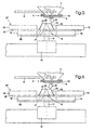
- the embodiment according to FIGS. 4 to 6 differs from the exemplary embodiments according to FIGS. 1 and 3 in that the smaller centrifugal discs 25 are arranged below the larger centrifugal disc 26 of the double disc 27.
- the shorter throwing blades 16 and on the upper centrifugal disc 15, the longer throwing blades 15 are arranged for the normal scattering.
- the lower centrifugal disc 25 is formed with the associated throwing blades 16 as border spreading disc and the upper centrifugal disc 26 with the associated throwing blades 15 as a normal scattering disc.
- the passage opening 17 is arranged in the upper centrifugal disc 26 in the upper centrifugal disc 26.
- the guide element 24, which is arranged on the metering elements, is set in accordance with FIG. 5 so that the fertilizer of the upper, i.e. the normal diffusion disc 26 is supplied while the guide element 24 is set according to FIG. 6 so that the material is supplied from the metering of the lower centrifugal disc 25 for boundary spreading.
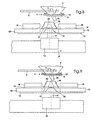
- FIGS. 7 to 9 differs from the preceding embodiments in that the guide member 24 is fixedly arranged on the metering member 4, while the drive member 12 with the centrifugal discs 5,13,14 relative to the metering member 4 and the lines 24 slidably is.
- the centrifugal discs 5,13,14 according to FIGS. 7 to 8 are formed according to the centrifugal discs 5,13,14 as shown in FIGS. 1 to 3. According to the setting according to FIG. 8, the assignment of the guide member 24 to the centrifugal discs 5, 13, 14 is such that the material is supplied via the guide element 24 to the upper centrifugal discs 14 and the throwing blades 16 arranged thereon.
- centrifugal discs By means of these centrifugal discs, a boundary spreading pattern can be achieved.
- the slinger 5,13,14 is moved with the drive member 12 in the direction of arrow 27 from the position shown in Fig. 8 in the position shown in Fig. 9.
- the material is passed to the lower centrifugal discs 13 and the throwing blades 15 arranged thereon via the guide element 24.
- the adjustment or displacement of the drive element 12 with the centrifugal discs can by hand or by means of a not shown motor filling element via a remote control or electronic control device.
- the difference between the embodiment of FIGS. 10 and 11 differs from the exemplary embodiments according to FIGS. 1 to 3.
- the difference lies in the fact that the changeover of the fertilizer feed of the fertilizer to the lower centrifugal disk 13 or upper centrifugal disk 14 is delayed by the displacement of the guide cone 18 done up or down.
- both the lower 13 and the upper centrifugal disc 14 corresponding recesses 28 and 29, so that the traffic cone 18 can be moved accordingly.
- the traffic cone 18 is in the pushed-up position, so that in this position, the upper centrifugal disc 14 from the metering 4, the material is supplied. Since the upper centrifugal disc 14 is formed with their throwing blades 16 as border spreading disc, the border spreading is performed in this position.
- the traffic cone 18 In order to carry out the normal scattering or to be able to supply the material of the lower centrifugal disc 13, the traffic cone 18 is displaced downwards into the position shown in FIG. In this position, the material of the lower centrifugal disc 13 and the throwing blades 15 arranged thereon is fed via the traffic cone 18.
- the lower centrifugal disk 13 of the double centrifugal disk 5 with the throwing blades 15 arranged thereon is designed as a normal scattering disk.
- the discs 14 and 13 are rotatably connected to each other via the throwing blade 15. About the connecting elements 30, the centrifugal disc 13 and thus the double disc 5 is rotatably connected to the shaft 11.
- the master controller 18 is slidably disposed on the sleeve 31 in different positions, at least in the upper and lower positions, optionally fixable on the drive shaft. For this purpose, appropriate fixing means may be provided.
- the centrifugal fertilizer spreader according to FIG. 12 has the reservoir 101, which is divided by the roof-shaped central part 102 into two outlet funnels 103.
- the outlet funnels 103 are each closed by a metering member 104 down.
- By means of these metering members 104 can be in adjustable amounts to feed the material below the metering members 104 centrifugal discs 105 in adjustable amounts.
- Above the metering members 104 the stirring shaft 106 is arranged with the stirring members 107 in the outlet funnels 103.
- the agitator shaft 106 is driven by means of the drive member 108 by a motor.
- the metering members 104 are designed as outlet openings which can be adjusted in their opening width by means of a slide 109 and which are located in the bottom plate 110 of the outlet funnel 103.
- the centrifugal discs 105 are designed as Doppelschleuderin and rotatably disposed on an upright and rotationally driven drive shaft 111.
- the drive elements 112 for the centrifugal discs 105 are formed in the embodiment as hydraulic motors, which are connected via not shown hydraulic lines and control elements with a hydraulic pump or hydraulic system.
- the centrifugal discs 105 are designed as Doppelschleuderusedn.
- the Doppelschleuderusionn 105 have the lower centrifugal disc 113 and the upper centrifugal disc 114.
- the lower centrifugal disc 113 has a larger diameter than the upper centrifugal disc 114.
- the throwing blades 115 arranged on the lower centrifugal disk 113 are longer than the throwing blades 116 arranged on the upper centrifugal disk 114.
- the upper centrifugal disk 114 has the passage opening 117.
- the guide cone 118 is arranged on the lower centrifugal disk 113 and the truncated cone 119 is arranged on the upper centrifugal disk 114.
- the truncated cone 119 is arranged with respect to the passage opening 117 such that the outer surface 120 of the truncated cone 119, the passage opening 117 against the resulting disc ring of the upper centrifugal disc 114 closes.
- a passage region 122 Between the inner surface 121 of the truncated cone 19 and the traffic cone 118 is a passage region 122, so that the material can pass from the metering member 104 to the lower centrifugal disc 113.
- the upper centrifugal disc 114 is rotatably fixed to the lower centrifugal disc 113 by connecting elements 123 connected. In the exemplary embodiment, these connecting elements 123 are formed by the throwing vanes 115 arranged on the lower centrifugal disk 113.
- an adjustable guide element 124 is arranged between the centrifugal discs 13 and 114 and the metering member 104. In the position shown with solid lines and according to the representation of DE-P 102 45 374, the guide element 124 is shown so that over the outer surface 120 of the guide cone 119 of the upper centrifugal disc 114 and the throwing vanes 116 of the upper centrifugal disc 114, the material is supplied.
- This guide element 124 is by means not shown adjusting means, which may also be designed by motor, in the position shown by dashed lines and the DE-P 102 45 374 shown position, so that the material in the reservoir 101 via the metering 104 and the Guide element 124 and located between the truncated cone 119 and the cone 120 passage area 122, the material of the lower centrifugal disc 113 and the throwing vanes 115 is fed.
- the upper centrifugal disc 114 with the throwing blades 116 is designed as a border spreading disc, while the lower centrifugal disc 113 with the lower discarding blades 115 is designed as a normal disc.
- the boundary diffusion disk 114 it is possible to achieve a spreading pattern having a steeply sloping scattering edge in the outer region, a so-called boundary spreading pattern or edge spreading pattern.
- the lower normal scattering disc 113 with the throwing blades 115 With the lower normal scattering disc 113 with the throwing blades 115, a normal scattering pattern with flat sloping scattering edges can be achieved for the purpose of overlapping adjacent scattering tracks.
- the hydraulic motors 112, the control valve 125 is assigned.
- the control valve 125 is connected via the lines 126 to the hydraulic motors 112. Furthermore, the control valve 125 is connected via connecting lines 127 to a hydraulic system. About the control valve 125, the hydraulic motors 112 can be driven according to the same or with or at different speeds.
- the centrifugal disk drive shafts 111 and centrifugal disks 113, 114 are each assigned a sensor 128 for determining the rotational speed of the centrifugal disks 113, 114. Both the control valve 125 and the speed sensors 128 are connected via transmission lines 129 to the electronic control device 130.
- the electronic control device 130 the corresponding control and regulating commands are transmitted to the control valve 125, so that the respective desired speed of the centrifugal discs 113,114 can be adjusted.
- the control valve 125 are controlled by the electronic control device 130, so that via the electronic control device 130, the rotational speed of the respective centrifugal disc 113,114 is adjustable.
- 130 data about the size, shape and / or contour of the field to be spread are stored in the electronic control device. Based on this input data is then by means of a location determination system, such as DGPS on the electronic control device 130, the speed of the respective centrifugal discs 13, 14 adjustable.
- the fertilizer spreader can be automatically adjusted accordingly, ie it can be switched automatically from standard spreading on border spreading. Furthermore, in this case the speed of the respective centrifugal disc 113, 114 can be correspondingly increased or decreased in order to vary the desired working width when the working width has to be changed, since the field is not rectilinear.
- variable speed mechanical transmission such as gear transmission, variator with V-belts or link chains.
- the variable-speed mechanical transmission is associated with a motor-operated adjustment device, which can be controlled and adjusted accordingly via the electronic control device 130.
Landscapes
- Life Sciences & Earth Sciences (AREA)
- Soil Sciences (AREA)
- Environmental Sciences (AREA)
- Fertilizing (AREA)
- Fertilizers (AREA)
- Treatment Of Sludge (AREA)
- Heat Treatment Of Steel (AREA)
- Crushing And Pulverization Processes (AREA)
- Extraction Or Liquid Replacement (AREA)
Applications Claiming Priority (5)
| Application Number | Priority Date | Filing Date | Title |
|---|---|---|---|
| DE10245374 | 2002-09-28 | ||
| DE2002145374 DE10245374A1 (de) | 2002-09-28 | 2002-09-28 | Schleuderdüngersteuer |
| DE10324647A DE10324647A1 (de) | 2002-09-28 | 2003-05-30 | Schleuderdüngerstreuer |
| DE10324647 | 2003-05-30 | ||
| PCT/EP2003/010695 WO2004030441A1 (de) | 2002-09-28 | 2003-09-25 | Schleuderdüngerstreuer |
Publications (2)
| Publication Number | Publication Date |
|---|---|
| EP1542525A1 EP1542525A1 (de) | 2005-06-22 |
| EP1542525B1 true EP1542525B1 (de) | 2006-04-19 |
Family
ID=32070696
Family Applications (1)
| Application Number | Title | Priority Date | Filing Date |
|---|---|---|---|
| EP03769324A Expired - Lifetime EP1542525B1 (de) | 2002-09-28 | 2003-09-25 | Schleuderdüngerstreuer |
Country Status (8)
| Country | Link |
|---|---|
| EP (1) | EP1542525B1 (da) |
| AT (1) | ATE323402T1 (da) |
| AU (1) | AU2003277905A1 (da) |
| BR (1) | BR0306502A (da) |
| DE (2) | DE10324647A1 (da) |
| DK (1) | DK1542525T3 (da) |
| EA (1) | EA200500428A1 (da) |
| WO (1) | WO2004030441A1 (da) |
Cited By (1)
| Publication number | Priority date | Publication date | Assignee | Title |
|---|---|---|---|---|
| DE102023003633A1 (de) * | 2023-09-07 | 2025-03-13 | Annaburger Nutzfahrzeug Gmbh | Streuwerk für ein landwirtschaftliches Streufahrzeug sowie landwirtschaftliches Streufahrzeug |
Families Citing this family (4)
| Publication number | Priority date | Publication date | Assignee | Title |
|---|---|---|---|---|
| ES2442955B1 (es) * | 2012-08-14 | 2014-11-18 | Aitor BRUN GARCÍA | Máquina distribuidora de material granulado |
| DE102015117151A1 (de) * | 2015-10-08 | 2017-04-13 | Aebi Schmidt Nederland Bv | Winterdienst-Streugerät |
| CA3207485A1 (en) | 2021-01-08 | 2022-07-14 | Benjamin Dwayne Boelter | System and method for controlling distribution pattern of centrifugal fertilizer spreaders |
| CA3211160A1 (en) | 2021-02-17 | 2022-08-25 | Highway Equipment Company | High output precision spinner |
Family Cites Families (6)
| Publication number | Priority date | Publication date | Assignee | Title |
|---|---|---|---|---|
| US2031540A (en) * | 1935-05-22 | 1936-02-18 | Joseph A Macaulay | Broadcast seeder |
| DE1757835U (de) | 1957-10-14 | 1957-12-12 | H & W Fritzen Maschf | Duengerstreuer. |
| FR1226288A (fr) * | 1959-06-04 | 1960-07-11 | Distributeur d'engrais | |
| GB1045370A (en) * | 1964-12-31 | 1966-10-12 | Mini Of The Ministerul Ind Con | Centrifugal distributor for fertilizers and other materials in powder or granules |
| DE3049070C1 (de) | 1980-12-24 | 1982-06-16 | Amazonen-Werke H. Dreyer Gmbh & Co Kg, 4507 Hasbergen | Schleuderstreuer,insbesondere zur Ausbringung von Duengemitteln |
| DE19717286A1 (de) | 1997-04-24 | 1998-10-29 | Amazonen Werke Dreyer H | Schleuderdüngerstreuer |
-
2003
- 2003-05-30 DE DE10324647A patent/DE10324647A1/de not_active Withdrawn
- 2003-09-25 BR BR0306502-2A patent/BR0306502A/pt not_active Application Discontinuation
- 2003-09-25 AU AU2003277905A patent/AU2003277905A1/en not_active Abandoned
- 2003-09-25 DE DE50303056T patent/DE50303056D1/de not_active Expired - Lifetime
- 2003-09-25 EA EA200500428A patent/EA200500428A1/ru unknown
- 2003-09-25 WO PCT/EP2003/010695 patent/WO2004030441A1/de not_active Ceased
- 2003-09-25 EP EP03769324A patent/EP1542525B1/de not_active Expired - Lifetime
- 2003-09-25 AT AT03769324T patent/ATE323402T1/de not_active IP Right Cessation
- 2003-09-25 DK DK03769324T patent/DK1542525T3/da active
Cited By (1)
| Publication number | Priority date | Publication date | Assignee | Title |
|---|---|---|---|---|
| DE102023003633A1 (de) * | 2023-09-07 | 2025-03-13 | Annaburger Nutzfahrzeug Gmbh | Streuwerk für ein landwirtschaftliches Streufahrzeug sowie landwirtschaftliches Streufahrzeug |
Also Published As
| Publication number | Publication date |
|---|---|
| DE50303056D1 (de) | 2006-05-24 |
| DK1542525T3 (da) | 2006-05-29 |
| BR0306502A (pt) | 2004-11-23 |
| AU2003277905A1 (en) | 2004-04-23 |
| EA200500428A1 (ru) | 2005-10-27 |
| ATE323402T1 (de) | 2006-05-15 |
| DE10324647A1 (de) | 2004-12-16 |
| EP1542525A1 (de) | 2005-06-22 |
| WO2004030441A1 (de) | 2004-04-15 |
Similar Documents
| Publication | Publication Date | Title |
|---|---|---|
| EP0445842B1 (de) | Schleuderdüngerstreuer mit Vorratsbehälter | |
| EP0540889B2 (de) | Schleuderdüngerstreuer | |
| DE3529452A1 (de) | Streugeraet | |
| EP0820219B1 (de) | Schleuderdüngerstreuer | |
| EP1542525B1 (de) | Schleuderdüngerstreuer | |
| DE4134315A1 (de) | Schleuderduengerstreuer | |
| EP0392288A2 (de) | Schleuderdüngerstreuer | |
| EP1707042B1 (de) | Zweischeibenstreuer für Streugut, insbesondere Dünger, Salz oder dergleichen | |
| EP1031268B1 (de) | Schleuderdüngerstreuer | |
| EP0988780A2 (de) | Verfahren zum Rand- und/oder Grenzstreuen | |
| EP1247437A2 (de) | Verfahren zum Verteilen von Streugut und Zentrifugalstreuer zur Durchführung des Verfahrens | |
| EP0910939A1 (de) | Schleuderstreuer | |
| EP0613613A1 (de) | Schleuderdüngerstreuer | |
| EP3847880A1 (de) | Landwirtschaftliche verteilmaschine | |
| EP0504720B1 (de) | Schleuderdüngerstreuer | |
| DE10245374A1 (de) | Schleuderdüngersteuer | |
| DD297905A5 (de) | Schleuderduengerstreuer | |
| EP0870423A1 (de) | Verfahren zum Ausbringen einer einzingen Düngersorte oder von gleichzeitig mehreren Düngersorten mit einem Schleuderdüngerstreuer | |
| DE4302802A1 (de) | Schleuderdüngerstreuer | |
| DE10033674A1 (de) | Schleuderdüngerstreuer | |
| DE4134317C2 (de) | Schleuderdüngerstreuer | |
| DE3343189A1 (de) | Vorrichtung zur dosierung von festen landwirtschaftlichen chemikalien | |
| DE102010016871A1 (de) | Schleuderstreuer | |
| DE19829782A1 (de) | Verfahren zum Einstellen eines Zentrifugaldüngerstreuers | |
| DE19646590A1 (de) | Schleuderdüngerstreuer |
Legal Events
| Date | Code | Title | Description |
|---|---|---|---|
| PUAI | Public reference made under article 153(3) epc to a published international application that has entered the european phase |
Free format text: ORIGINAL CODE: 0009012 |
|
| 17P | Request for examination filed |
Effective date: 20050321 |
|
| AK | Designated contracting states |
Kind code of ref document: A1 Designated state(s): AT BE BG CH CY CZ DE DK EE ES FI FR GB GR HU IE IT LI LU MC NL PT RO SE SI SK TR |
|
| AX | Request for extension of the european patent |
Extension state: AL LT LV MK |
|
| GRAP | Despatch of communication of intention to grant a patent |
Free format text: ORIGINAL CODE: EPIDOSNIGR1 |
|
| GRAS | Grant fee paid |
Free format text: ORIGINAL CODE: EPIDOSNIGR3 |
|
| DAX | Request for extension of the european patent (deleted) | ||
| GRAA | (expected) grant |
Free format text: ORIGINAL CODE: 0009210 |
|
| AK | Designated contracting states |
Kind code of ref document: B1 Designated state(s): AT BE BG CH CY CZ DE DK EE ES FI FR GB GR HU IE IT LI LU MC NL PT RO SE SI SK TR |
|
| PG25 | Lapsed in a contracting state [announced via postgrant information from national office to epo] |
Ref country code: SI Free format text: LAPSE BECAUSE OF FAILURE TO SUBMIT A TRANSLATION OF THE DESCRIPTION OR TO PAY THE FEE WITHIN THE PRESCRIBED TIME-LIMIT Effective date: 20060419 Ref country code: IE Free format text: LAPSE BECAUSE OF FAILURE TO SUBMIT A TRANSLATION OF THE DESCRIPTION OR TO PAY THE FEE WITHIN THE PRESCRIBED TIME-LIMIT Effective date: 20060419 Ref country code: SK Free format text: LAPSE BECAUSE OF FAILURE TO SUBMIT A TRANSLATION OF THE DESCRIPTION OR TO PAY THE FEE WITHIN THE PRESCRIBED TIME-LIMIT Effective date: 20060419 Ref country code: CZ Free format text: LAPSE BECAUSE OF FAILURE TO SUBMIT A TRANSLATION OF THE DESCRIPTION OR TO PAY THE FEE WITHIN THE PRESCRIBED TIME-LIMIT Effective date: 20060419 Ref country code: RO Free format text: LAPSE BECAUSE OF FAILURE TO SUBMIT A TRANSLATION OF THE DESCRIPTION OR TO PAY THE FEE WITHIN THE PRESCRIBED TIME-LIMIT Effective date: 20060419 Ref country code: FI Free format text: LAPSE BECAUSE OF FAILURE TO SUBMIT A TRANSLATION OF THE DESCRIPTION OR TO PAY THE FEE WITHIN THE PRESCRIBED TIME-LIMIT Effective date: 20060419 Ref country code: IT Free format text: LAPSE BECAUSE OF FAILURE TO SUBMIT A TRANSLATION OF THE DESCRIPTION OR TO PAY THE FEE WITHIN THE PRESCRIBED TIME-LIMIT;WARNING: LAPSES OF ITALIAN PATENTS WITH EFFECTIVE DATE BEFORE 2007 MAY HAVE OCCURRED AT ANY TIME BEFORE 2007. THE CORRECT EFFECTIVE DATE MAY BE DIFFERENT FROM THE ONE RECORDED. Effective date: 20060419 |
|
| REG | Reference to a national code |
Ref country code: GB Ref legal event code: FG4D Free format text: NOT ENGLISH |
|
| REF | Corresponds to: |
Ref document number: 50303056 Country of ref document: DE Date of ref document: 20060524 Kind code of ref document: P |
|
| REG | Reference to a national code |
Ref country code: IE Ref legal event code: FG4D Free format text: LANGUAGE OF EP DOCUMENT: GERMAN |
|
| PG25 | Lapsed in a contracting state [announced via postgrant information from national office to epo] |
Ref country code: SE Free format text: LAPSE BECAUSE OF FAILURE TO SUBMIT A TRANSLATION OF THE DESCRIPTION OR TO PAY THE FEE WITHIN THE PRESCRIBED TIME-LIMIT Effective date: 20060719 |
|
| PG25 | Lapsed in a contracting state [announced via postgrant information from national office to epo] |
Ref country code: ES Free format text: LAPSE BECAUSE OF FAILURE TO SUBMIT A TRANSLATION OF THE DESCRIPTION OR TO PAY THE FEE WITHIN THE PRESCRIBED TIME-LIMIT Effective date: 20060730 |
|
| GBT | Gb: translation of ep patent filed (gb section 77(6)(a)/1977) |
Effective date: 20060711 |
|
| PG25 | Lapsed in a contracting state [announced via postgrant information from national office to epo] |
Ref country code: PT Free format text: LAPSE BECAUSE OF FAILURE TO SUBMIT A TRANSLATION OF THE DESCRIPTION OR TO PAY THE FEE WITHIN THE PRESCRIBED TIME-LIMIT Effective date: 20060919 |
|
| PG25 | Lapsed in a contracting state [announced via postgrant information from national office to epo] |
Ref country code: MC Free format text: LAPSE BECAUSE OF NON-PAYMENT OF DUE FEES Effective date: 20060930 Ref country code: BE Free format text: LAPSE BECAUSE OF NON-PAYMENT OF DUE FEES Effective date: 20060930 |
|
| ET | Fr: translation filed | ||
| REG | Reference to a national code |
Ref country code: IE Ref legal event code: FD4D |
|
| PLBE | No opposition filed within time limit |
Free format text: ORIGINAL CODE: 0009261 |
|
| STAA | Information on the status of an ep patent application or granted ep patent |
Free format text: STATUS: NO OPPOSITION FILED WITHIN TIME LIMIT |
|
| 26N | No opposition filed |
Effective date: 20070122 |
|
| PG25 | Lapsed in a contracting state [announced via postgrant information from national office to epo] |
Ref country code: AT Free format text: LAPSE BECAUSE OF NON-PAYMENT OF DUE FEES Effective date: 20060925 |
|
| BERE | Be: lapsed |
Owner name: AMAZONEN-WERKE H. DREYER G.M.B.H. & CO. KG Effective date: 20060930 |
|
| PG25 | Lapsed in a contracting state [announced via postgrant information from national office to epo] |
Ref country code: GR Free format text: LAPSE BECAUSE OF FAILURE TO SUBMIT A TRANSLATION OF THE DESCRIPTION OR TO PAY THE FEE WITHIN THE PRESCRIBED TIME-LIMIT Effective date: 20060720 |
|
| REG | Reference to a national code |
Ref country code: CH Ref legal event code: PL |
|
| PG25 | Lapsed in a contracting state [announced via postgrant information from national office to epo] |
Ref country code: EE Free format text: LAPSE BECAUSE OF FAILURE TO SUBMIT A TRANSLATION OF THE DESCRIPTION OR TO PAY THE FEE WITHIN THE PRESCRIBED TIME-LIMIT Effective date: 20060419 Ref country code: BG Free format text: LAPSE BECAUSE OF FAILURE TO SUBMIT A TRANSLATION OF THE DESCRIPTION OR TO PAY THE FEE WITHIN THE PRESCRIBED TIME-LIMIT Effective date: 20060719 |
|
| PG25 | Lapsed in a contracting state [announced via postgrant information from national office to epo] |
Ref country code: LU Free format text: LAPSE BECAUSE OF NON-PAYMENT OF DUE FEES Effective date: 20060925 Ref country code: HU Free format text: LAPSE BECAUSE OF FAILURE TO SUBMIT A TRANSLATION OF THE DESCRIPTION OR TO PAY THE FEE WITHIN THE PRESCRIBED TIME-LIMIT Effective date: 20061020 Ref country code: LI Free format text: LAPSE BECAUSE OF NON-PAYMENT OF DUE FEES Effective date: 20070930 Ref country code: TR Free format text: LAPSE BECAUSE OF FAILURE TO SUBMIT A TRANSLATION OF THE DESCRIPTION OR TO PAY THE FEE WITHIN THE PRESCRIBED TIME-LIMIT Effective date: 20060419 Ref country code: CH Free format text: LAPSE BECAUSE OF NON-PAYMENT OF DUE FEES Effective date: 20070930 |
|
| PG25 | Lapsed in a contracting state [announced via postgrant information from national office to epo] |
Ref country code: CY Free format text: LAPSE BECAUSE OF FAILURE TO SUBMIT A TRANSLATION OF THE DESCRIPTION OR TO PAY THE FEE WITHIN THE PRESCRIBED TIME-LIMIT Effective date: 20060419 |
|
| PGFP | Annual fee paid to national office [announced via postgrant information from national office to epo] |
Ref country code: GB Payment date: 20080701 Year of fee payment: 6 |
|
| GBPC | Gb: european patent ceased through non-payment of renewal fee |
Effective date: 20090925 |
|
| PG25 | Lapsed in a contracting state [announced via postgrant information from national office to epo] |
Ref country code: GB Free format text: LAPSE BECAUSE OF NON-PAYMENT OF DUE FEES Effective date: 20090925 |
|
| REG | Reference to a national code |
Ref country code: FR Ref legal event code: PLFP Year of fee payment: 14 |
|
| REG | Reference to a national code |
Ref country code: FR Ref legal event code: PLFP Year of fee payment: 15 |
|
| REG | Reference to a national code |
Ref country code: FR Ref legal event code: PLFP Year of fee payment: 16 |
|
| PGFP | Annual fee paid to national office [announced via postgrant information from national office to epo] |
Ref country code: FR Payment date: 20180813 Year of fee payment: 16 Ref country code: DE Payment date: 20180911 Year of fee payment: 16 |
|
| PGFP | Annual fee paid to national office [announced via postgrant information from national office to epo] |
Ref country code: DK Payment date: 20180911 Year of fee payment: 16 Ref country code: NL Payment date: 20180912 Year of fee payment: 16 |
|
| REG | Reference to a national code |
Ref country code: DE Ref legal event code: R119 Ref document number: 50303056 Country of ref document: DE |
|
| REG | Reference to a national code |
Ref country code: DK Ref legal event code: EBP Effective date: 20190930 |
|
| REG | Reference to a national code |
Ref country code: NL Ref legal event code: MM Effective date: 20191001 |
|
| PG25 | Lapsed in a contracting state [announced via postgrant information from national office to epo] |
Ref country code: NL Free format text: LAPSE BECAUSE OF NON-PAYMENT OF DUE FEES Effective date: 20191001 Ref country code: DE Free format text: LAPSE BECAUSE OF NON-PAYMENT OF DUE FEES Effective date: 20200401 |
|
| PG25 | Lapsed in a contracting state [announced via postgrant information from national office to epo] |
Ref country code: FR Free format text: LAPSE BECAUSE OF NON-PAYMENT OF DUE FEES Effective date: 20190930 Ref country code: DK Free format text: LAPSE BECAUSE OF NON-PAYMENT OF DUE FEES Effective date: 20190930 |