EP1542450A1 - Procédé et dispositif d'établissement de trames par diffusion d'erreurs de vecteurs issus de tables - Google Patents
Procédé et dispositif d'établissement de trames par diffusion d'erreurs de vecteurs issus de tables Download PDFInfo
- Publication number
- EP1542450A1 EP1542450A1 EP04292942A EP04292942A EP1542450A1 EP 1542450 A1 EP1542450 A1 EP 1542450A1 EP 04292942 A EP04292942 A EP 04292942A EP 04292942 A EP04292942 A EP 04292942A EP 1542450 A1 EP1542450 A1 EP 1542450A1
- Authority
- EP
- European Patent Office
- Prior art keywords
- vector
- index
- pixel
- coordinates
- correspondence table
- Prior art date
- Legal status (The legal status is an assumption and is not a legal conclusion. Google has not performed a legal analysis and makes no representation as to the accuracy of the status listed.)
- Granted
Links
- 239000013598 vector Substances 0.000 title claims abstract description 195
- 238000000034 method Methods 0.000 title claims abstract description 27
- 238000009792 diffusion process Methods 0.000 title claims description 23
- 238000004364 calculation method Methods 0.000 claims description 19
- 238000006243 chemical reaction Methods 0.000 claims description 19
- 239000003086 colorant Substances 0.000 description 17
- 238000010276 construction Methods 0.000 description 7
- 238000010586 diagram Methods 0.000 description 7
- 238000000605 extraction Methods 0.000 description 3
- 230000009897 systematic effect Effects 0.000 description 3
- 238000012216 screening Methods 0.000 description 2
- 230000000007 visual effect Effects 0.000 description 2
- 230000008859 change Effects 0.000 description 1
- 235000021183 entrée Nutrition 0.000 description 1
- 230000006870 function Effects 0.000 description 1
- 239000011159 matrix material Substances 0.000 description 1
- 239000000203 mixture Substances 0.000 description 1
- 230000008569 process Effects 0.000 description 1
- 230000009467 reduction Effects 0.000 description 1
Images

Classifications
-
- H—ELECTRICITY
- H04—ELECTRIC COMMUNICATION TECHNIQUE
- H04N—PICTORIAL COMMUNICATION, e.g. TELEVISION
- H04N1/00—Scanning, transmission or reproduction of documents or the like, e.g. facsimile transmission; Details thereof
- H04N1/46—Colour picture communication systems
- H04N1/56—Processing of colour picture signals
- H04N1/60—Colour correction or control
- H04N1/6058—Reduction of colour to a range of reproducible colours, e.g. to ink- reproducible colour gamut
-
- H—ELECTRICITY
- H04—ELECTRIC COMMUNICATION TECHNIQUE
- H04N—PICTORIAL COMMUNICATION, e.g. TELEVISION
- H04N1/00—Scanning, transmission or reproduction of documents or the like, e.g. facsimile transmission; Details thereof
- H04N1/40—Picture signal circuits
- H04N1/405—Halftoning, i.e. converting the picture signal of a continuous-tone original into a corresponding signal showing only two levels
- H04N1/4051—Halftoning, i.e. converting the picture signal of a continuous-tone original into a corresponding signal showing only two levels producing a dispersed dots halftone pattern, the dots having substantially the same size
- H04N1/4052—Halftoning, i.e. converting the picture signal of a continuous-tone original into a corresponding signal showing only two levels producing a dispersed dots halftone pattern, the dots having substantially the same size by error diffusion, i.e. transferring the binarising error to neighbouring dot decisions
-
- H—ELECTRICITY
- H04—ELECTRIC COMMUNICATION TECHNIQUE
- H04N—PICTORIAL COMMUNICATION, e.g. TELEVISION
- H04N1/00—Scanning, transmission or reproduction of documents or the like, e.g. facsimile transmission; Details thereof
- H04N1/46—Colour picture communication systems
- H04N1/52—Circuits or arrangements for halftone screening
Definitions
- the present invention applies to the field of electronics and more particularly to the establishment of signals representative of frames of colors to allow printing by a printing device or their display by display means (LCD, CRT or plasma screens).
- the present invention relates to a method of establishing frames by vector error diffusion using tables stored in a memory of a device for determining the vector error of the successive pixels.
- a frame is a set of successive lines consisting of successive points (or pixels) whose representative values of two-dimensional arrangement and chromatic compositions and / or luminance define an image. Dithering corresponds to the attribution a color and / or luminance at each pixel of the frame.
- Diffusion dithering methods are known in the prior art errors in which the gray levels of the pixels of an image in progress dithering are compared to a threshold to give pixels the color black or white color.
- the error corresponding to the approximation made is kept in memory for influence the comparison with the threshold of the following pixels in the frame.
- the error made on each pixel is thus broadcast on the neighboring pixels. Thanks to this diffusion of error, pixels whose different levels of gray, for example 8-bit coded, are not directly printable or displayable are transformed into black or white pixels coded on 1 bit whose combination has the same visual appearance as grayscale original.
- pixels whose exact color for example encoded on 32 bits
- pixels whose exact color can not be printed or displayed directly are transformed into pixels composed of directly printable colors or displayable (eg 8-bit coded) and whose combination presents the same visual appearance as the original colors.
- the present invention aims to overcome certain disadvantages of the prior art by proposing a method for establishing vector error diffusion frames that is easily implementable in integrated circuits and fast, because it does not require calculation systematic reference vector closest to the representative vector of each pixel and that it does not use dimension tables too much important.
- This object is achieved by a method of setting frame signals by vector error diffusion, realizing a representation of the signals representative of the pixels of the image in "vectors" of a space whose least one dimension corresponds to a chromatic component or luminance and in which certain vectors, called “reference vectors”, represent a directly printable color combination or displayable by the devices to which the frame is intended, characterized in that it includes a step of extraction of the nearest reference vector of a given vector by consulting at least one correspondence table between an input index of the given vector in the correspondence table and a reference index of the reference vector closest to that given vector, said correspondence table being of reduced dimensions compared to the number of possible color pixel vectors, thanks to the fact that an index of entry in this table corresponds to a plurality of vectors having their end in the same region of said space multidimensional, in which the approximation of these vectors to the vector whose end is in the center of the region introduces an invisible error by the human eye.
- the calculation of the entry index in said correspondence table of the representative vector of the pixel being treatment equivalent to determining the range of coordinates in which is this vector, consists in reducing the precision of the coordinates of this vector and is an approximation of the vector at vector whose end is at the center of the range of coordinates in which end of the vector is included.
- the step of converting the index of reference extract in color index and / or luminance directly can be used by the printing or display device is carried out by consulting an index conversion table containing, in connection with the benchmarks of the correspondence table, values used by the printing or display devices to determine the chromatic and / or luminance characteristics of a point.
- the step of converting the index of reference extracted from said correspondence table in coordinates of reference vector in said space is made by consulting a vector conversion table containing the coordinates of the vectors of reference in said space in relation to their reference indices in the correspondence table.
- the calculation of the vector error consists in the calculation of an error vector whose coordinates, in said space multidimensional, are equal to the difference between the coordinates of the extracted reference vector and those, kept in memory, of the vector representative of the pixel being processed.
- the diffusion of the vector error memorized consists in adding, in the said multidimensional space, coordinates of a calculated and stored error vector for a pixel at coordinates of the vectors representative of the following and neighboring pixels in the frame.
- Another object of the invention is to propose a device that can be used on an image taking apparatus or an image representation apparatus (for example a printer), overcoming the disadvantages of the prior art.
- a frame setting device of signals characterized in that it comprises a correspondence table stored in a memory and containing color indices and / or luminance that can be used by a printing or display device, a memory for storing the image to be processed, means for converting each pixel of the image as a vector of a space of which at least a dimension corresponds to a chromatic component and / or luminance of reference and determination of an index corresponding to this vector to access reading at the correspondence table and means reading in the correspondence table of a reference index of color and / or luminance usable by a printing device or display.
- the present invention will be described in connection with FIGS. 1 to 4 and relates to a method and a device for setting frames (1) by distributing vector errors (52) from a table (3).
- the invention uses a conventional vector-based dithering method but relies on the use of a correspondence table (3).
- Screening by diffusion of vector error (52) realizes a representation (15) of the successive pixels of an image in vectors (20) in a multidimensional space (2), of which at less certain dimensions correspond to chromatic components and / or luminance, by means of conversion means of each pixel of the image as a vector of a space.
- reference vector (51) some represent a combination of colors, called reference or basic colors, directly printable or viewable by the devices to which the frame is destiny and are called reference color combination vectors, abbreviated reference vector (51).
- reference vector (51) For each representative vector (20) of a pixel (11) being processed, the reference vector (51) the most is sought by calculating the minimum vector error (52), i.e. the minimum distance between the end of the vector (20) representative of the pixel and the end of one of the reference vectors (51).
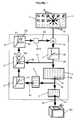
- Figure 1 shows the novelty of the present invention, which is that the choice of the reference vector (51) closest to the vector (20) representing the pixel (11) being processed is not done by a systematic calculation of the minimum vector error during dithering.
- This systematic calculation is replaced by the consultation (30) of a correspondence table (3) stored in a memory, for example a device allowing the capture of the image (camera or camera) or the representation of the image (printer, display).
- the consultation (30) of this table of correspondence (3) by means of reading means in the table, allows to extract a reference index (31) which is then converted, thanks to a second table (4), in a color index (41), directly usable (40) by the devices (100) to which the frame is intended.
- the index (31) of reference is also converted (50), thanks to a third table (5), in one reference vector (51) which will allow the calculation of the vector error (52) made for this pixel.
- the vector error (52) introduced for the pixel (11) processed is stored in an error memory (5210) and will then be diffused (60) to the next and neighboring pixels in the frame, by the addition of a error vector (521) stored at the representative vectors of the pixels neighbors and following.
- the frame is a representation of the image in form of a matrix of pixels, in a storage memory of the image to be processed in the frame setting device.
- the next and neighboring pixels of a given pixel in the frame are the one that follows this pixel processed in the same line and those lying on the next line and surrounding this pixel treaty.
- the vector representation (15) (20) of the pixel (11) being processing is influenced by the vector errors introduced on the pixels (10) previous and neighboring in the frame.
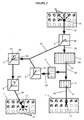
- FIG. 2 shows the method for processing a given pixel (11), during the establishment of a frame (1), in which the pixels already processed and stored are shown in hatched form, the stored pixels not processed are shown in dotted lines and the pixel being processed is represented in black.
- the arrows between some pixels of the frame symbolize vector error diffusion.
- the representation (15) of the current pixel (11) of vector processing (20) in space (2) is influenced by errors vector images made on the previous and neighboring pixels (10) in the frame (1) (this diffusion is represented by the arrows in the frame in the upper right part of the diagram).
- the coordinates of this vector, stored (21) in memory are converted (25) by an approximation described below, in an index (29) of entry in the table (3) of correspondence which allows the extraction (30) of the index (31) of reference.
- An index conversion table (4) allows the conversion (40) of this index (31) index reference (41) which defines a color combination directly usable by the device to which the frame (1) is intended.
- This index (41) thus makes it possible to attribute a color to the pixel (11) being processing (shown as hatched as all pixels processed in the frame of the lower right of the diagram).
- the consultation (50) of a conversion table (5) vector allows, from the index (31) of reference, to determine the corresponding reference vector (51).
- the comparison of coordinates of this vector (51) of reference with those kept in memory of the vector (20) representative of the pixel (11) being processed defines the error vector (52) made on this pixel (11).
- This vector error consists of an error vector (521) which is stored in a memory (5210) of error and which will be added to the coordinates of the vectors representing the following pixels in the frame (1).
- This diffusion (60) of vector error is represented by the arrows of the pixel (11) being processed to the following (12) in the frame shown in the lower left of the diagram.
- the calculation the minimum vector error (52), to find the reference vector closest to the representative vector of the pixel being processed, is realized during the construction of the correspondence table and the results, converted into indices, are stored in this table (3).
- the conversion of the results into input indexes in the table allows a reduction in the number of values to store.
- at each input index in the table correspond several vectors whose coordinates are considered as equivalent. This equivalence is based on the power of resolution of the human eye in the different dimensions of space (2) used for pixel representation.
- Figure 3 represents the realized approximation, by which an index defines a volume (8) corresponding to coordinate ranges in which several vectors (80) have their end.
- All these vectors (80) are assimilated to the vector (81) whose end is at the center of the volume (8) of coordinates defined by an index of entry into the table.
- the difference between a vector of the range of coordinates and the vector whose end is finds in the center of this range introduced an error (82) of approximation.
- the size of the coordinate range is calculated so that the error maximum approximation is less than, equal to or slightly greater than resolution power of the human eye.
- the Table construction shown in Figure 4, consists of calculating the minimum vector error (52) for each index (29) defining a range of coordinates in which several vectors (20) may have their end, looking for the reference vector (51) closest to the vector whose end is at the center of this range of coordinates.
- the index of the reference vector (51) chosen by means of this calculation is entered in the correspondence table (3) as reference index (31), in relation with the index (29) defining a range of coordinates.
- the method according to the invention is iterated for all the pixels of the frame, as shown on the Figure 1.
- the data representative of the pixel (11) being processed are converted to data representing a vector (20) in said space (2) defined and the coordinates of the vector are kept (21) in memory.
- a simple calculation (25) can determine in which coordinate range its end is inscribed and therefore which index (29) defines it at the input of the correspondence table (3).
- This calculation (25) corresponds to an approximation (82, figure 3) of the coordinates of the vector and consists in rounding the values, for example by truncation of the least significant bits in the binary code representative of the coordinates of the vector.
- This conversion may also consist of a calculation, for example in the case a fixed relationship between the two indices. To possibly avoid this conversion stage, the exact values of the reference indices can be have been established so that they can be used directly by the devices to which the frame is intended.
- the reference index (31) is also converted to reference vector coordinates (51) in said space (2) by the consultation (50) of a conversion table (5) Vector.
- An error vector (521) defined by the difference between coordinates of the reference vector (51) and those kept in memory of the vector (20) representative of the pixel being processed, is calculated for determining the vector error (52) of the processed pixel to be broadcast to the pixels following and neighboring in the frame.
- the diffusion (60) of this vector error will consist of adding the coordinates of this error vector (521) to coordinates of the vectors representing the following and neighboring pixels in the frame. All the pixels of the frame are therefore represented by vectors whose coordinates are adjusted according to possible errors vector images made on the next and neighboring pixels.
Landscapes
- Engineering & Computer Science (AREA)
- Multimedia (AREA)
- Signal Processing (AREA)
- Image Processing (AREA)
Abstract
Description
- représentation d'un pixel dans ledit espace sous la forme de signaux représentatifs d'un vecteur dont les coordonnées sont stockées en mémoire après ajustement, en fonction des erreurs vectorielles mémorisées éventuellement introduites sur les pixels précédents et voisins dans la trame ;
- calcul de l'indice d'entrée dans ladite table de correspondance de ce vecteur représentatif du pixel en cours de traitement ;
- extraction, à partir de ladite table de correspondance, de l'indice de référence du vecteur de référence le plus proche de ce vecteur représentatif du pixel, inscrit en relation avec l'indice calculé pour ce vecteur représentatif du pixel ;
- conversion de cet indice de référence extrait en un indice de couleur et/ou de luminance, directement utilisable par le dispositif d'impression ou d'affichage ;
- conversion de cet indice de référence extrait en signaux représentatifs de coordonnées de vecteur de référence dans ledit espace et calcul de l'erreur vectorielle introduite pour ce pixel ;
- enregistrement de cette erreur vectorielle introduite pour ce pixel et diffusion aux pixels suivants et voisins dans la trame, lors de leur représentation en vecteurs.
- détermination de la plage de coordonnées de vecteurs définie par un indice de ladite table de correspondance et calcul du vecteur dont l'extrémité est au centre de cette plage de coordonnées ;
- détermination des indices de référence définissant les plages de coordonnées contenant les vecteurs de référence ;
- recherche du vecteur de référence le plus proche du vecteur dont l'extrémité est au centre de la plage de coordonnées définie par l'indice ;
- inscription de l'indice de référence choisi en relation avec l'indice des plages de coordonnées de vecteurs.
- la figure 1 représente un schéma de l'algorithme itéré pour chaque pixel d'une image lors de la mise en oeuvre du procédé selon l'invention de tramage par diffusion d'erreur vectorielle issue d'une table ;
- la figure 2 représente un schéma du procédé selon l'invention de tramage par diffusion d'erreur vectorielle issue d'une table, pour un pixel donné de l'image ;
- la figure 3 représente un schéma de l'approximation réalisée au cours de la construction de la table de correspondance ;
- la figure 4 représente un schéma du principe de la construction de la table de correspondance.
Claims (9)
- Procédé d'établissement de trame (1) par diffusion d'erreur vectorielle, réalisant une représentation (15) des pixels en dits « vecteurs » (20) dans un espace (2) dont au moins une dimension correspond à une composante chromatique ou de luminance et dans lequel certains vecteurs, dits «vecteurs de référence » (51), représentent une combinaison de couleurs directement imprimable ou affichable par les dispositifs auxquels la trame est destinée, caractérisé en ce qu'il comporte une étape d'extraction du vecteur (51) de référence le plus proche d'un vecteur (20) donné, par consultation (30) d'au moins une table (3) de correspondance entre un indice (29) d'entrée d'un vecteur (20) donné dans la table (3) de correspondance et un indice (31) de référence du vecteur (51) de référence le plus proche de ce vecteur (20) donné, ladite table (3) de correspondance étant de dimensions réduites par rapport au nombre de vecteurs de pixel couleur possibles, grâce au fait qu'un indice (8) d'entrée dans cette table (3) correspond à une pluralité de vecteurs (80) possédant leur extrémité dans une même région (8) dudit espace (2) pluridimensionnel, dans laquelle l'approximation (82) de ces vecteurs (80) au vecteur (81) dont l'extrémité se trouve au centre de la région introduit une erreur invisible par l'oeil humain.
- Procédé d'établissement de trame selon la revendication 1, caractérisé en ce qu'il consiste en la répétition des étapes suivantes pour chaque pixel de la trame (1) :représentation (15) d'un pixel (11) dans ledit espace (2) sous la forme d'un vecteur (20) dont les coordonnées sont stockées (21) en mémoire après ajustement, en fonction des erreurs vectorielles mémorisées éventuellement introduites sur les pixels (10) précédents et voisins dans la trame ;calcul (25) de l'indice (29) d'entrée dans ladite table (3) de correspondance de ce vecteur (20) représentatif du pixel (11) en cours de traitement ;extraction (30), à partir de ladite table (3) de correspondance, de l'indice (31) de référence du vecteur (51) de référence le plus proche de ce vecteur (20) représentatif du pixel (11), inscrit en relation avec l'indice (29) calculé pour ce vecteur représentatif du pixel ;conversion (40) de cet indice (31) de référence extrait en un indice (41) de couleur et/ou de luminance, directement utilisable par le dispositif (100) d'impression ou d'affichage ;conversion (50) de cet indice (31) de référence extrait en coordonnées de vecteur (51) de référence dans ledit espace (2) et calcul de l'erreur vectorielle (52) introduite pour ce pixel ;enregistrement de cette erreur vectorielle (52) introduite pour ce pixel et diffusion (60) aux pixels suivants et voisins dans la trame, lors de leur représentation (15) en vecteurs.
- Procédé d'établissement de trame selon l'une des revendications 1 et 2, caractérisé en ce que les valeurs contenues dans ladite table (3) de correspondance ont été calculées par répétition des étapes suivantes pour chaque indice de la table de correspondance :détermination de la plage de coordonnées de vecteurs (20) définie par un indice (29) de ladite table (3) de correspondance et calcul du vecteur dont l'extrémité est au centre de cette plage de coordonnées ;détermination des indices (31) de référence définissant les plages de coordonnées contenant les vecteurs (51) de référence ;recherche du vecteur (51) de référence le plus proche du vecteur dont l'extrémité est au centre de la plage de coordonnées définie par l'indice ;inscription de l'indice (31) de référence choisi en relation avec l'indice (29) des plages de coordonnées de vecteurs.
- Procédé d'établissement de trame selon l'une des revendications 1 à 3, caractérisé en ce que le calcul (25) de l'indice d'entrée dans ladite table (3) de correspondance du vecteur (20) représentatif du pixel (11) en cours de traitement, équivalent à la détermination de la plage de coordonnées dans laquelle se trouve ce vecteur, consiste à réduire la précision des coordonnées de ce vecteur et constitue une approximation du vecteur au vecteur dont l'extrémité se trouve au centre de la plage de coordonnées dans laquelle l'extrémité du vecteur est comprise.
- Procédé d'établissement de trame selon l'une des revendications 1 à 4, caractérisé en ce que l'étape de conversion (40) de l'indice (31) de référence extrait en indice (41) de couleur et/ou de luminance directement utilisable par le dispositif (100) d'impression ou d'affichage est réalisée par consultation d'une table (4) de conversion d'indices contenant, en relation avec les indices (31) de référence de la table de correspondance, des valeurs utilisables par les dispositifs (100) d'impression ou d'affichage pour déterminer les caractéristiques chromatiques et/ou de luminance d'un point.
- Procédé d'établissement de trame selon l'une des revendications 1 à 5, caractérisé en ce que l'étape de conversion (50) de l'indice (31) de référence extrait de ladite table (3) de correspondance en coordonnées de vecteur (51) de référence dans ledit espace (2) est réalisée par consultation d'une table (5) de conversion vectorielle contenant les coordonnées des vecteurs (51) de référence dans ledit espace (2) en relation avec leurs indices (31) de référence dans la table de correspondance.
- Procédé d'établissement de trame selon l'une des revendications 1 à 6, caractérisé en ce que le calcul de l'erreur vectorielle (52) consiste en le calcul d'un vecteur d'erreur (521) dont les coordonnées, dans ledit espace (2) pluridimensionnel, sont égales à la différence entre les coordonnées du vecteur (51) de référence extrait et celles, gardées en mémoire, du vecteur (20) représentatif du pixel (11) en cours de traitement.
- Procédé d'établissement de trame selon l'une des revendications 1 à 7, caractérisé en ce que la diffusion (60) de l'erreur vectorielle mémorisée consiste en l'ajout, dans ledit espace (2) pluridimensionnel, des coordonnées d'un vecteur d'erreur (521) calculé et mémorisé pour un pixel (11) aux coordonnées des vecteurs représentatifs des pixels (12) suivants et voisins dans la trame (1).
- Dispositif d'établissement de trame (1), pour la mise en oeuvre du procédé selon une des revendications 1 à 8, caractérisé en ce qu'il comporte une table (3) de correspondance mémorisée dans une mémoire et contenant des indices de couleurs et/ou de luminance utilisables par un dispositif (100) d'impression ou d'affichage, une mémoire de stockage de l'image à traiter, des moyens de conversion de chaque pixel de l'image sous forme d'un vecteur (20) d'un espace (2) dont au moins une dimension correspond à une composante chromatique et/ou de luminance de référence et de détermination d'un indice correspondant à ce vecteur pour accéder en lecture à la table de correspondance et des moyens de lecture dans la table de correspondance d'un indice de référence de couleur et/ou de luminance utilisable par un dispositif d'impression ou d'affichage.
Applications Claiming Priority (2)
| Application Number | Priority Date | Filing Date | Title |
|---|---|---|---|
| FR0314608A FR2863806B1 (fr) | 2003-12-12 | 2003-12-12 | Procede et dispositif d'etablissement de trames par diffusion d'erreurs de vecteurs issus de tables |
| FR0314608 | 2003-12-12 |
Publications (2)
| Publication Number | Publication Date |
|---|---|
| EP1542450A1 true EP1542450A1 (fr) | 2005-06-15 |
| EP1542450B1 EP1542450B1 (fr) | 2013-03-20 |
Family
ID=34508657
Family Applications (1)
| Application Number | Title | Priority Date | Filing Date |
|---|---|---|---|
| EP20040292942 Ceased EP1542450B1 (fr) | 2003-12-12 | 2004-12-10 | Procédé et dispositif d'établissement de trames par diffusion d'erreurs de vecteurs issus de tables |
Country Status (2)
| Country | Link |
|---|---|
| EP (1) | EP1542450B1 (fr) |
| FR (1) | FR2863806B1 (fr) |
Cited By (1)
| Publication number | Priority date | Publication date | Assignee | Title |
|---|---|---|---|---|
| WO2014158621A1 (fr) * | 2013-03-14 | 2014-10-02 | Qualcomm Incorporated | Reproduction de couleur spectrale au moyen d'un écran réfléchissant de grandes dimensions |
Citations (2)
| Publication number | Priority date | Publication date | Assignee | Title |
|---|---|---|---|---|
| US5070413A (en) * | 1989-10-10 | 1991-12-03 | Eastman Kodak Company | Color digital halftoning with vector error diffusion |
| US5455600A (en) * | 1992-12-23 | 1995-10-03 | Microsoft Corporation | Method and apparatus for mapping colors in an image through dithering and diffusion |
-
2003
- 2003-12-12 FR FR0314608A patent/FR2863806B1/fr not_active Expired - Fee Related
-
2004
- 2004-12-10 EP EP20040292942 patent/EP1542450B1/fr not_active Ceased
Patent Citations (2)
| Publication number | Priority date | Publication date | Assignee | Title |
|---|---|---|---|---|
| US5070413A (en) * | 1989-10-10 | 1991-12-03 | Eastman Kodak Company | Color digital halftoning with vector error diffusion |
| US5455600A (en) * | 1992-12-23 | 1995-10-03 | Microsoft Corporation | Method and apparatus for mapping colors in an image through dithering and diffusion |
Non-Patent Citations (2)
| Title |
|---|
| FLETCHER P: "A SIMD PARALLEL COLOUR QUANTIZATION ALGORITHM", COMPUTERS AND GRAPHICS, PERGAMON PRESS LTD. OXFORD, GB, vol. 15, no. 3, 1991, pages 365 - 373, XP000224934, ISSN: 0097-8493 * |
| HECKBERT P: "Color image quantization for frame buffer display", COMPUT. GRAPH. (USA), COMPUTER GRAPHICS, JULY 1982, USA, vol. 16, no. 3, July 1982 (1982-07-01), pages 297 - 307, XP002292139, ISSN: 0097-8930 * |
Cited By (5)
| Publication number | Priority date | Publication date | Assignee | Title |
|---|---|---|---|---|
| WO2014158621A1 (fr) * | 2013-03-14 | 2014-10-02 | Qualcomm Incorporated | Reproduction de couleur spectrale au moyen d'un écran réfléchissant de grandes dimensions |
| US9129547B2 (en) | 2013-03-14 | 2015-09-08 | Qualcomm Incorporated | Spectral color reproduction using a high-dimension reflective display |
| KR20150130471A (ko) * | 2013-03-14 | 2015-11-23 | 퀄컴 인코포레이티드 | 고차원 반사형 디스플레이를 이용한 분광색 재현 |
| CN105190737A (zh) * | 2013-03-14 | 2015-12-23 | 高通股份有限公司 | 使用高维反射式显示器的光谱色彩再现 |
| CN105190737B (zh) * | 2013-03-14 | 2017-03-15 | 高通股份有限公司 | 使用高维反射式显示器的光谱色彩再现 |
Also Published As
| Publication number | Publication date |
|---|---|
| FR2863806A1 (fr) | 2005-06-17 |
| FR2863806B1 (fr) | 2006-02-03 |
| EP1542450B1 (fr) | 2013-03-20 |
Similar Documents
| Publication | Publication Date | Title |
|---|---|---|
| US8351720B2 (en) | Method and system providing edge enhanced image binarization | |
| FR2698507A1 (fr) | Diffusion d'erreur de couleur. | |
| JP3437226B2 (ja) | 画像処理方法及び装置 | |
| CN111611192B (zh) | 彩屏阅读器的刷新方法、彩屏阅读器及计算机存储介质 | |
| FR2524744A1 (fr) | Appareil de traitement d'images | |
| FR2724521A1 (fr) | Systeme de traitement d'image a multiples plages de tonalites | |
| Li et al. | Fusion-based underwater image enhancement with category-specific color correction and dehazing | |
| WO2018142040A1 (fr) | Procede de traitement d'une image d'entree, dispositif, equipement terminal et programme d'ordinateur associe | |
| FR2538983A1 (fr) | Procede de correction de couleur applicable a la prise de vues video et systeme mettant en oeuvre ce procede | |
| FR2779601A1 (fr) | Procede de reproduction d'une carte des couleurs a point noir k-seul en reduisant les parasites d'interpolateur | |
| EP1542450B1 (fr) | Procédé et dispositif d'établissement de trames par diffusion d'erreurs de vecteurs issus de tables | |
| BE1021013B1 (fr) | Procede et systeme pour ameliorer la qualite d'images en couleur. | |
| EP1544793A1 (fr) | Procédé et système d'amélioration de la qualité d'images numériques surexposées | |
| JPH0722327B2 (ja) | カラー画像処理装置 | |
| EP1549044B1 (fr) | Procédé et dispositif d'établissement de trames par décision de niveaux de saturation chromatique et diffusion d'erreur | |
| EP1553754B1 (fr) | Procédé et dispositif d'établissement de trames par diffusion d'erreur et limitation d'encre par matrices de valeurs de seuils | |
| JPH02228878A (ja) | 画像処理装置 | |
| FR3054707A3 (fr) | Procede d'acquisition d'images en couleurs sous eclairage ambiant inconnu | |
| BE1017576A6 (fr) | Procede d'agrandissement rapide d'images en couleur. | |
| JP2001320593A (ja) | 画像処理装置およびそれを備えた画像形成装置ならびに画像処理方法 | |
| JP2978060B2 (ja) | カラー画像データ変換方法 | |
| Durcan et al. | Digital image files in light microscopy | |
| Xu et al. | Research on Image Enhancement Algorithm Based on Hybrid Generative Adversarial Network | |
| BE1022166B1 (fr) | Procede de compression d'images | |
| De Pontual | Aide à l'estimation des stocks d'huîtres en élevage par télédétection basse altitude: étude de faisabilité |
Legal Events
| Date | Code | Title | Description |
|---|---|---|---|
| PUAI | Public reference made under article 153(3) epc to a published international application that has entered the european phase |
Free format text: ORIGINAL CODE: 0009012 |
|
| AK | Designated contracting states |
Kind code of ref document: A1 Designated state(s): AT BE BG CH CY CZ DE DK EE ES FI FR GB GR HU IE IS IT LI LT LU MC NL PL PT RO SE SI SK TR |
|
| AX | Request for extension of the european patent |
Extension state: AL BA HR LV MK YU |
|
| 17P | Request for examination filed |
Effective date: 20051214 |
|
| RAP1 | Party data changed (applicant data changed or rights of an application transferred) |
Owner name: SAGEM COMMUNICATION |
|
| AKX | Designation fees paid |
Designated state(s): DE ES GB IT |
|
| 17Q | First examination report despatched |
Effective date: 20060922 |
|
| RAP1 | Party data changed (applicant data changed or rights of an application transferred) |
Owner name: SAGEM COMMUNICATIONS |
|
| RAP1 | Party data changed (applicant data changed or rights of an application transferred) |
Owner name: SAGEM COMMUNICATIONS SAS |
|
| RAP1 | Party data changed (applicant data changed or rights of an application transferred) |
Owner name: SAGEM COMMUNICATIONS |
|
| RAP1 | Party data changed (applicant data changed or rights of an application transferred) |
Owner name: SAGEM COMMUNICATIONS SAS |
|
| RAP1 | Party data changed (applicant data changed or rights of an application transferred) |
Owner name: SAGEMCOM DOCUMENTS SAS |
|
| REG | Reference to a national code |
Ref country code: DE Ref legal event code: R079 Ref document number: 602004041396 Country of ref document: DE Free format text: PREVIOUS MAIN CLASS: H04N0001520000 Ipc: G09G0005060000 |
|
| RIC1 | Information provided on ipc code assigned before grant |
Ipc: G09G 5/06 20060101AFI20120522BHEP |
|
| RIC1 | Information provided on ipc code assigned before grant |
Ipc: H04N 1/405 20060101ALI20120531BHEP Ipc: G09G 5/06 20060101AFI20120531BHEP |
|
| GRAJ | Information related to disapproval of communication of intention to grant by the applicant or resumption of examination proceedings by the epo deleted |
Free format text: ORIGINAL CODE: EPIDOSDIGR1 |
|
| GRAP | Despatch of communication of intention to grant a patent |
Free format text: ORIGINAL CODE: EPIDOSNIGR1 |
|
| GRAJ | Information related to disapproval of communication of intention to grant by the applicant or resumption of examination proceedings by the epo deleted |
Free format text: ORIGINAL CODE: EPIDOSDIGR1 |
|
| GRAP | Despatch of communication of intention to grant a patent |
Free format text: ORIGINAL CODE: EPIDOSNIGR1 |
|
| GRAS | Grant fee paid |
Free format text: ORIGINAL CODE: EPIDOSNIGR3 |
|
| GRAA | (expected) grant |
Free format text: ORIGINAL CODE: 0009210 |
|
| AK | Designated contracting states |
Kind code of ref document: B1 Designated state(s): DE ES GB IT |
|
| REG | Reference to a national code |
Ref country code: GB Ref legal event code: FG4D Free format text: NOT ENGLISH |
|
| REG | Reference to a national code |
Ref country code: DE Ref legal event code: R096 Ref document number: 602004041396 Country of ref document: DE Effective date: 20130516 |
|
| PG25 | Lapsed in a contracting state [announced via postgrant information from national office to epo] |
Ref country code: ES Free format text: LAPSE BECAUSE OF FAILURE TO SUBMIT A TRANSLATION OF THE DESCRIPTION OR TO PAY THE FEE WITHIN THE PRESCRIBED TIME-LIMIT Effective date: 20130701 |
|
| PLBE | No opposition filed within time limit |
Free format text: ORIGINAL CODE: 0009261 |
|
| STAA | Information on the status of an ep patent application or granted ep patent |
Free format text: STATUS: NO OPPOSITION FILED WITHIN TIME LIMIT |
|
| 26N | No opposition filed |
Effective date: 20140102 |
|
| PG25 | Lapsed in a contracting state [announced via postgrant information from national office to epo] |
Ref country code: IT Free format text: LAPSE BECAUSE OF FAILURE TO SUBMIT A TRANSLATION OF THE DESCRIPTION OR TO PAY THE FEE WITHIN THE PRESCRIBED TIME-LIMIT Effective date: 20130320 |
|
| REG | Reference to a national code |
Ref country code: DE Ref legal event code: R097 Ref document number: 602004041396 Country of ref document: DE Effective date: 20140102 |
|
| PGFP | Annual fee paid to national office [announced via postgrant information from national office to epo] |
Ref country code: GB Payment date: 20141126 Year of fee payment: 11 Ref country code: DE Payment date: 20141121 Year of fee payment: 11 |
|
| REG | Reference to a national code |
Ref country code: DE Ref legal event code: R119 Ref document number: 602004041396 Country of ref document: DE |
|
| GBPC | Gb: european patent ceased through non-payment of renewal fee |
Effective date: 20151210 |
|
| PG25 | Lapsed in a contracting state [announced via postgrant information from national office to epo] |
Ref country code: DE Free format text: LAPSE BECAUSE OF NON-PAYMENT OF DUE FEES Effective date: 20160701 Ref country code: GB Free format text: LAPSE BECAUSE OF NON-PAYMENT OF DUE FEES Effective date: 20151210 |