EP1542323B1 - Overvoltage protection device, based on spark gaps, comprising at least two main electrodes arranged in an enclosed housing - Google Patents
Overvoltage protection device, based on spark gaps, comprising at least two main electrodes arranged in an enclosed housing Download PDFInfo
- Publication number
- EP1542323B1 EP1542323B1 EP04021959.4A EP04021959A EP1542323B1 EP 1542323 B1 EP1542323 B1 EP 1542323B1 EP 04021959 A EP04021959 A EP 04021959A EP 1542323 B1 EP1542323 B1 EP 1542323B1
- Authority
- EP
- European Patent Office
- Prior art keywords
- protection device
- overvoltage protection
- voltage
- spark gap
- arc
- Prior art date
- Legal status (The legal status is an assumption and is not a legal conclusion. Google has not performed a legal analysis and makes no representation as to the accuracy of the status listed.)
- Not-in-force
Links
Images


Classifications
-
- H—ELECTRICITY
- H01—ELECTRIC ELEMENTS
- H01T—SPARK GAPS; OVERVOLTAGE ARRESTERS USING SPARK GAPS; SPARKING PLUGS; CORONA DEVICES; GENERATING IONS TO BE INTRODUCED INTO NON-ENCLOSED GASES
- H01T4/00—Overvoltage arresters using spark gaps
- H01T4/16—Overvoltage arresters using spark gaps having a plurality of gaps arranged in series
- H01T4/20—Arrangements for improving potential distribution
-
- H—ELECTRICITY
- H01—ELECTRIC ELEMENTS
- H01T—SPARK GAPS; OVERVOLTAGE ARRESTERS USING SPARK GAPS; SPARKING PLUGS; CORONA DEVICES; GENERATING IONS TO BE INTRODUCED INTO NON-ENCLOSED GASES
- H01T2/00—Spark gaps comprising auxiliary triggering means
- H01T2/02—Spark gaps comprising auxiliary triggering means comprising a trigger electrode or an auxiliary spark gap
-
- H—ELECTRICITY
- H01—ELECTRIC ELEMENTS
- H01T—SPARK GAPS; OVERVOLTAGE ARRESTERS USING SPARK GAPS; SPARKING PLUGS; CORONA DEVICES; GENERATING IONS TO BE INTRODUCED INTO NON-ENCLOSED GASES
- H01T4/00—Overvoltage arresters using spark gaps
- H01T4/10—Overvoltage arresters using spark gaps having a single gap or a plurality of gaps in parallel
- H01T4/12—Overvoltage arresters using spark gaps having a single gap or a plurality of gaps in parallel hermetically sealed
Definitions
- the invention relates to a spark arrestor overvoltage protection device, comprising at least two main electrodes located in a pressure-tight housing and at least one auxiliary starting electrode, wherein a functional subassembly for reducing the response voltage of the spark gap is housed in the housing volume, which is in communication with one of the main electrodes and the auxiliary ignition electrode.
- a functional subassembly for reducing the response voltage of the spark gap is housed in the housing volume, which is in communication with one of the main electrodes and the auxiliary ignition electrode.
- the starting aids for high-performance surge arresters are designed for use in low-voltage networks between L and N or else N and PE as active ignition aids.
- These ignition aids generate a high ignition voltage with the aid of a pulse transformer, through which one of the partial sections is covered in a typical three-electrode spark gap arrangement.
- the disadvantage of such a solution is on the one hand the sometimes considerable space requirement of the ignition aid, which usually consists of a plurality of components, and on the other hand, the resulting interference factors.
- this ignition device limits the design possibilities for the main functional element, namely the actual spark gap, given the relatively small dimensions of the surge arresters. This limitation not only concerns the volume generally available, but also the need for the necessary additional contacting of a third electrode.
- the design of the electrodes according to DE 101 57 817 A1 would also be relatively large, so on the one hand the ignition aid can be added and on the other hand, the ignition aid is protected from the influence of temperature of the thermally heavily loaded electrodes. Furthermore, there is the need for frictional connection to produce reproducible distances of the partial spark gaps between the electrodes, whereby the ignition aid is not only thermally but also loaded by mechanical forces. Also occur strong dynamic loads between the electrodes in response to the spark gap. Further restrictions arise in this arrangement when used in a spark gap for network applications.
- network spark gaps In contrast to the spark gap, network spark gaps must master and resolve secondary currents in the kA range, which not only causes further and in particular longer-acting thermal loads, but also corresponding consequential current-quenching or even consequential current-limiting measures have to be implemented.
- network spark gaps In particular, with regard to the possibilities of limiting the reticule current in conventional dimensions of the surge arresters for grid application, which are generally smaller than separating spark gaps, leads an arrangement as in DE 101 57 817 A1 to extreme limitations in choosing a suitable method of limiting current.
- the DE 195 10 181 A1 is an ignition aid from a first spark gap, which serves to ignite a flashover, and a second spark gap, which is the first connected in parallel and the deletion of the secondary stream, presented. Furthermore, reference is made to the integration of a passive, simple ignition aid in a spark gap.
- the first spark gap is used to set the response voltage and the resulting spark of the pre-ionization of the second, longer and more current-carrying spark gap. Due to the pre-ionization and the voltage drop across the impedance connected in series with the spark gap, the second spark gap is ignited.
- the second spark gap has, in contrast to the first spark gap, a high surge current carrying capacity and a good follow current extinguishing capability.
- spark gaps According to the stack spark gap for medium and high voltage applications after US 3,223,874 individual spark gaps have an ignition aid for preionization.
- This arrangement can be carried out at least partially encapsulated.
- such a type of spark gaps is only designed for low surge current loads of 8/20 ⁇ s and can not withstand the pressures and force effects of significant lightning surge currents.
- the extinguishing capability for follow-on currents which is partially present in such an arrangement results for the most part from the series connection of a multiplicity of partial spark gaps, each with a starting aid.
- the ignition aid is connected directly to the respective main electrodes of the spark gap. It has no third auxiliary electrode and there is no direct discharge directly between the main electrodes.
- the type of preionization is based there on partial discharges, which spread over both sides of the surface of an existing insulation part.
- a spark discharge as is commonly used in modern low-voltage arresters, does not exist because the auxiliary electrodes of the ignition aid are located on opposite sides of the insulator.
- This form of ignition aid is sufficient at high potential differences of several kV for rapid ignition.
- the response voltage is ⁇ 1 kV, such an embodiment of a starting aid is not efficient.
- the entire Zündhne is defenseless the effect of the arc exposed, which can lead both to disruption in their function as well as to complete destruction.
- auxiliary spark gaps in which a spark discharge is possible.
- the discharge from the auxiliary spark gap in which the current flow is limited by various measures, is transferred to the main electrodes.
- the auxiliary spark gap would have to be equipped with a suitable ignition aid regardless of the delay time to ignite the main spark gap to even a response voltage of z. B. ⁇ 1kV to keep reliable.
- the WO 03/021735 A1 shows a simplified ignition aid for surge arrester, which may be located at least partially inside the spark gap.
- This ignition aid is based on a series connection of a voltage switching element and a so-called ignition element.
- the response voltage of the arrester is advantageously determined by the voltage-switching element.
- the main spark gap is ignited by the fact that after ignition of the voltage-switching element, a current flows through the ignition element, whereby a voltage is built up over the main spark gap.
- the spark travels along the firing element and extends until the main spark gap rolls over.
- This solution has functionally significant disadvantages.
- the crucial component for safe operation is the so-called ignition element.
- the inserted spring for making contact and tracking of the ignition element may possibly track in case of burning or demolition of the tip of the ignition element.
- the spring can avoid neither a complete break of the ignition element after changes in the contact point due to the formation of melt on the electrode or on the ignition element or the deposits of impurities in the contact area.
- the spring must also be protected from burn-off products and the thermal and dynamic stresses caused by the arc. With a small or even delayed sparking, however, increases the Zündverzugszeit the main spark gap.
- this can significantly increase the electrical load on the voltage-switching element and also of the ignition element; on the other hand, the voltage across the ignition element and thus over the entire spark gap increases sharply. This also endangers the elements to be protected and the desired low residual voltage values of the lightning arrester.
- Another disadvantage of the cited solution is that the distance of the main electrodes is directly connected to the length of the ignition element.
- a relatively large main electrode spacing is often advantageous.
- the response voltage between the electrodes that is, at higher distances, a greater preionization between the main electrodes must be made, so that it can lead to the rollover at the desired low voltages.
- the distance at which the spark must travel from the bad pad length ens until it reaches the other major electrode. This also restricts, as already mentioned, the choice of the usual means for the sequence current deletion or limitation.
- the spark gap arrangement after DE 199 52 004 A1 can be operated with both an active and a highly simplified passive ignition aid. These ignition aids are all outside the spark gap. Moreover, the Zünd Anlagenn consist of a variety of components, which should take over the task of fine protection. However, this requires relatively large and powerful components, whereby integration into the spark gap is difficult. However, the task of fine protection also requires a relatively high power consumption and an additional thermal load. In the passive ignition aid, which advantageously consists of only a few components, although the space requirement would reduce, but the problem of power conversion remains in the realization of fine protection. The disadvantage is in the DE 199 52 004 A1 Furthermore, that the response of the overall arrangement by the geometric design of the spark gap is determined. In this case, the response voltage of the shorter separation path thus defines the response voltage of the entire arrester. The Anschschreiben achievable in this way, however, are not resistant to aging and strongly dependent on the load condition of the spark gap.
- a spark arrester overvoltage protection device in particular for low-voltage applications comprising at least two located in a pressure-tight housing main electrodes and at least one auxiliary ignition, which avoids possible sources of interference between ignition aid and spark gap and the principle in all known method for subsequent current deletion, follow current limiting or even the avoidance of subsequent currents in spark gaps can be used.
- the solution to be specified should therefore allow universal applications, regardless of the specific electrode geometry.
- the object of the invention is achieved with a surge protection device on spark gap basis according to the combination of features according to claim 1, wherein the dependent claims represent at least expedient refinements and developments.
- a simplified starting aid which consists of at least one voltage-switching element, an impedance and an isolating distance.
- the simplified ignition aid is integrated between two main electrodes and completely in the pressure-resistant housing of the overvoltage protection device, ie in the spark gap itself and is part of this. Occurs on such an arrangement, an overvoltage that exceeds the sum of the operating voltages of the switching element and the separation distance of the series circuit, so the ignition aid, whereby a current through the voltage switching element, the impedance and the associated separation distance from the first main electrode to the second main electrode flows.
- the flameproof enclosure is designed for the control of pressures up to several 10 bar as a result of the strains of the spark gap during lightning and line flow. In case of a possible overload of the ignition aid, the damage potential is thus essentially limited by the flameproof enclosure of the spark gap. This also eliminates additional protective measures of the ignition itself, such. B. fuses or the like. A possibly desired evaluation of the state of the arrester is also greatly facilitated, since only the overall function, measurable at the outer terminals of the spark gap, and not individual components, connections and components must be monitored.
- the Zündanges function module for selectively reducing the operating voltage of the spark gap from a fully integrated into the pressure-tight housing, located outside the arc combustion chamber series connection of a voltage-switching element, an impedance and a separation path is formed, wherein the separation distance by the distance of the auxiliary ignition electrode nearest main electrode is defined.
- the voltage switching element may for example be a gas arrester. It is also possible to form the voltage-switching element as a suppressor diode, thyristor, varistor and / or as a defined erosion-resistant air or sliding spark gap.
- the auxiliary ignition electrode can itself be designed impedance-related and have a complex resistance.
- the auxiliary ignition electrode extends partially into the arc combustion chamber or is located in this.
- the auxiliary ignition electrode may be made of a conductive plastic or a plastic with conductive additives, such as. B. conductive fibers.
- the impedance in turn consists of a material with a nonlinear or linear resistance profile.
- the impedance can also consist of a conductive plastic or a conductive ceramic.
- the auxiliary ignition electrode is insulated from the main electrode, wherein the response voltages of each of the main electrodes resulting sub-sections are chosen differently.
- the response voltage e 1 of the first main electrode to the auxiliary ignition electrode is much larger than the response voltage of the further separation distance e 2 selected.
- the overvoltage protection device has means for flowing the arc with hard gas.
- hard-gas-releasing material surrounds at least portions of the arc-combustion chamber, wherein the hard-gas-emitting material additionally has conductive properties to the potential of one of Main electrodes should be brought to the separation distance of the auxiliary ignition electrode.
- a pressure equalization port prevents accumulation of an undesirable increase in pressure over time.
- the pressure equalization port may be formed by the housing or by electrode materials which are at least partially gas permeable.
- portions of the housing may consist of a porous polymer material, porous ceramic or correspondingly porous metal.
- the overvoltage protection device can have residual voltage limiting means.
- the conductive, hard-gas-emitting material which is electrically connected to one of the main electrodes, in a defined geometry and with defined electrical properties, so that the targeted influencing of the course and the height of the residual voltage can be realized.
- the resistance of the hard gas-emitting material to the impedance of the series connection of the functional element is lower.
- the conductive, hard gas-emitting material carries during the load with surge current as well as with subsequent currents part of each flowing total current, so that increases the reliability of the device according to the invention and its long-term stability.
- the proportion of current which is taken over by the conductive, hard-gas-emitting material is virtually adjustable by the ratio of the resistance of this material to the resistance value of the arc.
- the average value of the resistance of the conductive, hard gas-emitting material is chosen to be greater than the average, mean resistance value of the arc.
- the voltage-switching element and / or the discrete impedance can be integrated into one of the main electrodes.
- one of the main electrodes have an externally accessible cavity, whereby also, if necessary, an interchangeability of the voltage-switching element is ensured.
- the voltage-switching element is inserted in a single-pole insulated manner in the cavity, wherein the cavity has an internal thread for receiving a conductive screw contacting the inserted voltage-switching element.
- the end of the auxiliary ignition electrode reaching the arc combustion chamber lies essentially at the same level as the end of the main electrode which reaches into the combustion chamber and is associated with the first separation zone.
- the Zündangeselektrode laterally offset and / or relative to the arc main combustion chamber set back to protect this can be arranged.
- a supplementary voltage-switching element which is located outside the pressure-tight enclosure, an adjustment or adjustment of the operating voltage of the overvoltage protection device can take place.
- the presented overvoltage protection device can also be implemented as a combination of a triggerable partial spark gap high response voltage and at least one downstream partial spark gap low response voltage.
- the partial spark gaps may include means for internal potential control.
- the partial spark gaps are mechanically fixed and connected via spacers.
- the spacers may consist of a conductive, field-controlling material.
- the spacers and the electrodes of the partial spark gaps may have a sheath, wherein the sheath comprises a shield which is electrically connected on one side for targeted potential distortion or is designed as such itself.
- the distance of the electrodes which form the partial spark gap with auxiliary ignition electrode is preferably chosen to be greater than the spacing of the electrodes which define the respectively following partial spark gaps.
- the spacer can be performed for the non-triggerable by the auxiliary ignition partial spark gap as an integral component in terms of manufacturing rationalization and easier installation.
- additional insulating sections or insulating materials preferably provided in the outer region of the electrodes of the partial spark gap or arranged there.
- the spacers have on their side remote from the arc combustion chamber on an insulation coating or insulation sheath, which is a complementary measure to avoid unwanted flashovers.
- the spark gap according to the invention can be embodied as a horn spark gap or else as a stack spark gap.
- the passive ignition aid 100 accordingly Fig. 1 is integrated into the flameproof enclosure 5 of the spark gap, which has two main electrodes 1 and 2. These main electrodes 1 and 2 are kept isolated in an example of metallic encapsulation 5 with respect to this.
- the ignition aid 100 consists of a voltage-switching element 4, preferably a gas arrester, but also suppressor diodes, thyristors, varistors, defined erosion-resistant separation sections or a combination of these elements are suitable. Furthermore, the starting aid 100 has an impedance-dependent auxiliary starting electrode 3. There is also the possibility that a discrete impedance 3a exists as a separate element.
- impedance 3a elements or materials such as plastics or ceramics with linear, but also with non-linear resistances or characteristic curves are suitable.
- this z. B. as a resistor, as a varistor, as a capacitor or even made of materials with corresponding characteristics of such devices.
- the auxiliary ignition electrode or ignition electrode 3 is insulated from the two main electrodes 1 and 2.
- the response voltages of the resulting partial spark gaps e 1 and e 2 are designed differently.
- the response voltage of the distance e 1 , ie the main electrode 1 to the auxiliary ignition electrode 3 is much larger than the response voltage of the distance e 2 , formed by the distance of the main electrode 2 to the auxiliary ignition electrode.
- the response voltage of the distance e 1 is at least equal, but generally higher than the response voltage of the voltage-switching element 4 of the ignition aid 100th
- the response voltage of the distance e 2 is at most equal but generally lower than the response voltage of the voltage-switching element 4 of the ignition aid 100.
- the response voltage of the entire arrester is essentially determined by the response voltage of the voltage-switching element 4 and thus can be selected independently of the usual geometric conditions of the main spark gap.
- all functionally relevant parts for the response are not exposed to the direct action of arcing. Only one end of the Zündiselektrode 3, which preferably own impedance, z. B. can be performed as a conductive plastic is located partially in the arc combustion chamber and is isolated from the two main electrodes 1, 2 executed.
- auxiliary ignition electrode 3 is not made of an impedance-sensitive material, but of a low-resistance material, for. As copper, or the like is carried out, as already mentioned, a separate impedance 3a is used, which is then located completely outside the direct arc action.
- the unavoidable burning of all parts in the arc combustion chamber can damage the auxiliary starting electrode 3 only partially. Since the arc erosion takes place on all sides in the entire combustion chamber of the spark gap, all the combustion chamber delimiting parts, including the auxiliary ignition electrode 3, are gradually burned off with their adjacent insulation parts. This ensures that the geometric proportions of all components remain largely the same after each load. As a result of uneven burning or as a result of contamination, however, damage to or bridging of the short insulation gap e 2 may also occur in this geometry. In particular, in almost all active external ignition aids this would virtually for short circuit of the pulse transformer and thus lead to failure or overloading of the ignition aid. However, this is not the case with the design proposed here according to the exemplary embodiment.
- the resulting impurities as well as the usually only partial contact bridges, which are formed by melting phenomena and due to the design of the components are only slightly, have a relatively high resistance and are eliminated by a low current flow.
- the electrical parameters of the components integrated in the spark gap are predetermined on the one hand by the geometric dimensions.
- the power conversion is also limited in favor of a simple construction of the contact points and also the thermal load of the insulation stretches.
- the performance of the ignition aid in the present embodiment is limited to small impulse powers.
- Fig. 1 In the description of the general functional description Fig. 1 is shown a basic, simplified geometry of a possible spark gap arrangement. In this arrangement, which relates only to the ignition range, no measures to follow current limit are included for simplicity.
- the main electrodes 1 and 2 are manufactured in known manner from erosion-resistant, electrically conductive materials such as metals, metallic alloys, sintered metals, graphite, ceramics or composite ceramics.
- auxiliary starting electrode 3 With regard to the auxiliary starting electrode 3, it should also be noted that, as stated, these are themselves either made of a material having a high impedance, e.g. Resistance material, electrically conductive plastic, plastic with filler or is connected to a separate impedance 3a in the form of a resistor.
- a material having a high impedance e.g. Resistance material, electrically conductive plastic, plastic with filler or is connected to a separate impedance 3a in the form of a resistor.
- the plastic material of the auxiliary ignition electrode can not only soot or graphite elements or to set desired impedance properties Metal or carbon fibers contained, but it is possible to introduce micro varistors or nanotubes.
- the main electrode 1 is connected to the voltage switching element 4, which is a gas discharge tube, a gas discharge tube with Microgap; a spark gap, an isolating path, a suppressor diode, a varistor or a combination of the aforementioned elements may be connected to the impedance 3a or the auxiliary starting electrode 3 within the outer pressure-resistant encapsulation 5 of the spark gap.
- the voltage switching element 4 is a gas discharge tube, a gas discharge tube with Microgap; a spark gap, an isolating path, a suppressor diode, a varistor or a combination of the aforementioned elements may be connected to the impedance 3a or the auxiliary starting electrode 3 within the outer pressure-resistant encapsulation 5 of the spark gap.
- the three electrodes form two parting lines e 1 and e 2 , wherein e 2 has a significantly lower response voltage than the separation distance e 1 .
- the response voltage of the subsection e 2 is equal to or less than the response voltage of the voltage switching element 4. Since the Gleichan Anlagenportion the entire arrester should be equal to or less than 1 kV, there are special requirements for the execution of the separation distance e 2nd This separation distance e 2 can z. B. by thin films of erosion-resistant materials or by temperature-resistant coatings, but also by means of special erosion-resistant paints can be realized.
- a spark is produced between the auxiliary starting electrode 3 and the main electrode 2.
- the current flows from the main electrode 1 via the impedance 3a, the auxiliary starting electrode 3 and the spark to the main electrode 2.
- This spark brings charge carriers into the interior of the spark gap, whereby the dielectric strength of the separation distance e 1 is reduced very quickly.
- a voltage difference which is essentially determined by the magnitude of the current in the ignition circuit and the impedance 3a. This voltage difference exceeds the reduced by the charge carrier input withstand voltage of the isolating distance e 1, so these lights, takes over the current and relieves the ignition circuit.
- the partial arcs over the separation lines e 1 and e 2 connect and the spark gap ignites between the main electrodes 1 and 2.
- Fig. 2 shows a spark gap for grid applications, in particular between L and N. This spark gap is able to produce higher arc voltages. These are realized in the present case by flowing the arc with hard gas.
- the effect can also be exploited by electrically conductive additives, such as metal fibers, carbon black, carbon fibers, microvaristors, nanotubes, metal particles, semiconductor particles or even per se conductive polymers, the potential of the main electrode 2 to lead to the separation distance of the auxiliary ignition electrode 3.
- electrically conductive additives such as metal fibers, carbon black, carbon fibers, microvaristors, nanotubes, metal particles, semiconductor particles or even per se conductive polymers
- the spark occurs between the auxiliary ignition electrode 3 and the conductive hard gas-emitting material 10 and can then extend very quickly to the main electrode 2 already or only after the rollover of the separation distance e 1 .
- the arc length is increased and on the other hand, the arc cooled by the hard gas and flowed.
- the operating voltage of the spark gap is from a pressure increase z. B. when using gas discharge arresters as a voltage-switching element 4 is not affected.
- the distance between the two main electrodes can be extended without influencing the response voltage by using appropriately conductive materials 10.
- the size of the conductive, hard gas-emitting part 10 is preferably chosen to be larger than the dimensions of the separation distance e 1 .
- the amount of residual stress in the spark gap arrangement according to Fig. 1 and 2 can be classified into three areas.
- a first time range begins, as it were, after the voltage-switching element has responded and the separation gap e 2 flashes.
- the impedance of all these elements determines the voltage drop across the arrester. If the, reduced by the pre-ionization strength of the distance e 1 is exceeded, there is a flashover between the main electrode 1 and the part 10. This results in a discharge of the ignition circuit and it reduces the residual voltage by the voltage drop across the ignition circuit. Now, the residual stress is determined essentially by the part 10.
- the residual voltage increases during this period as a function of the currently effective impedance and the pulse current. At high voltage gradients or surge currents, the residual voltage may therefore assume too high values, whereby a hazard or even an overload of the downstream elements may occur.
- the task of an effective residual voltage limiting is additionally transmitted to the conductive, hard-gas-emitting part 10.
- a certain dimensioning of the resistance of the part 10 is required according to the embodiment.
- a targeted influence on the course and the height of the residual stress can be done by the rest in addition to the electrical design of the part 10 by the geometric.
- Is the resistance of member 10 chosen to be relatively high impedance relative to the impedance 3a the residual stress increases even after the breakdown of the separation distance s 1 to pass. So it would be particular In the case of large dimensions (length) of the part 10 (greater ignition delay time) there is the risk of an excessively high residual voltage at high pulse currents.
- Is the resistance of the part 10 on the other hand chosen 3a low compared to the impedance the rise in the residual voltage can be reduced after the roll of the separating section e 1, whereby the risk of excessive residual stress is significantly reduced.
- the effective effective resistance of the part 10 can be influenced by the material, the geometry of the part and the respective contact surface of the part 10 on the electrode 2. Equally effective, however, is the design of the transition region between the part 10 and the auxiliary ignition electrode 10 and the positioning of the main electrode 1. If the Zündangeselektrode 3 z. B. is executed with a larger inner diameter than the part 10, it is compared to the part as quasi reset, there is a virtually larger contact surface on the part 10 for the spark between the main electrode 1 and the part 10 itself, resulting in a lower effective resistance of Part 10 sets. If the auxiliary ignition electrode is practically present in the arc combustion chamber, the resistance increases. It can also be carried out in the direction of the axes analogous measures of geometric design.
- the height of the resistance of the part 10, for example, as a hollow cylinder with an Au dated micr of 18 mm, an inner diameter of 4 mm at a Height of 5 mm can practically be varied between several hundred k ⁇ and values up to approx. 1 ⁇ without any negative effects regarding the extinguishing capacity of the spark gap and the material selection.
- the maximum limitation of the residual voltage results, as explained, at lowest resistance values.
- the resistance of the part 10 of a spark gap according to Fig. 2 or 3 attains a special significance not only in the residual stress, but also in its effect on the subsequent current quenching.
- the part 10 is in the described arrangements basically parallel to the arc or at least to portions of the arc. This applies to all loads in which the spark gap between the main electrode 1 and 2 is ignited.
- the part 10 always takes over a portion of the total current both during the load with surge currents as well as the load with subsequent currents. The amount of this portion is dependent on the height of the resistance of the part 10 and the quasi-resistance of the arc.
- the current-voltage characteristic of an arc is not linear, but depends on numerous factors, including the composition of the gas, pressure, temperature and so on. These variables are determined in a real spark gap, inter alia, by the geometry, the materials used and the electrical load. Because of all these sizes Even with fixed spark gap geometry vary greatly due to aging, the exact arc curve can only be predicted insufficient. However, considering the follow current arc at AC voltage, it is also known that the resistance of the arc at the time of ignition and at the time of extinction is in part significantly increased. In this time range, therefore, the parallel resistance of the part 10 takes on a correspondingly higher proportion of current or even the total current at low values ⁇ 10 ⁇ . As a result, charge carriers are naturally removed from the arc, as a result of which the ionization decreases greatly. This leads to premature extinction of the arc. Part 10 leads here the follow current up to the current zero crossing.
- the low resistance value of the part 10 may also serve to avoid a line follow current arc.
- the mains voltage is relatively low in relation to the driving voltage of the pulse current and also dependent on the phase position.
- the parallel resistance of the part 10 virtually reduces the voltage load on the switching path, as a result of which the ignition of the line follow current arc can be prevented.
- the follow-on current can for one thing be completely prevented or, on the other hand, only a limited follow-on current flows through the part 10 until the current zero crossing. In this mode of action, the extinguishing and firing tips of the arc are avoided. This effect is a positive side effect, with the rest still no risk of damage to the part 10 is independent of the selected conductive material.
- the resistance of the part 10 corresponds approximately to the resistance of the follow-current arc, is to be expected with a strong current load of the part 10 over the entire arc phase. Therefore, only those materials are used that can not be damaged by a sustained current and temperature effect.
- the arc resistance has a value of substantially 0.5 to 1 ⁇ in the case of a follow-up current. If this value is exceeded by the part 10, this leads on the one hand to a heavy load on the part 10, but on the other hand, the arc can be deleted faster or it is an ignition preventable.
- a safe operation and a hardly limited choice of material for the part 10 is given in particular when the average resistance of the part 10 is generally higher than the average resistance of the arc.
- interpretations may be useful in which by lowering the average value of the resistance of the part 10 below the mean value of the resistance of the follow-current arc, an arc should be largely avoided in the follow-on current.
- Conceivable here are conductive ceramics, composite materials, varistor material or the use of PTC material.
- Fig. 4 to 7 show further design variants of the integrated ignition aid in combination with a spark gap with follow current extinction according to the hard gas principle.
- the voltage switching element 4 is integrated directly into a recess of the main electrode 1 for protection against, in particular, thermal and mechanical loads.
- This recess can, for. B. in the form of a bore in the power supply of the main electrode.
- This hole can have an internal thread.
- one side of the voltage-switching element 4 is insulated from the main electrode 1 and there is an insulated conductive connection or connection to the auxiliary starting electrode 3.
- the Zündangeselektrode 3 is introduced into the arc-combustion chamber quasi at the same height with the reaching to the arc-combustion end of the main electrode 1. This causes after the ignition of the main spark gap very quickly extinguishing the current in the ignition circuit, since this is practically no longer exposed to a potential difference.
- the Zündoselektrode 3 is thus protected from direct arcing capacabbrand.
- Fig. 6 shows a representation in which the auxiliary ignition electrode 3 is arranged laterally offset from the arc combustion chamber, which also sets a special protected embodiment of the electrode 3.
- the illustrated ignition aid described in the exemplary embodiment can also be applied to other extinguishing principles or electrode arrangements.
- Known sequence current extinguishing method for low-voltage arrester in addition to the variants explained is z.
- horn-shaped electrodes for arc extension often in combination with arc-free arrangements, or even the generation of high pressures to increase the arc field strength.
- a series circuit of multiple spark gaps for multiplying the electrode drop voltage is conceivable.
- spark gaps of advantage in which the cost, which is necessary in terms of flow and cooling of the gas released, is to be limited, or even at spark gaps, where the lowest possible aging is of interest.
- Hartgasabbinede substances can partially or completely replaced by electrically conductive substances with linear, but also with non-linear characteristics.
- This can z. B. pressure-resistant conductive ceramics, fiber ceramics or composite materials with conductive components or else, for example, materials with varistor characteristic or a PTC characteristic.
- the pressure build-up is due to the limited internal volume z. B. realized in a cylinder.
- a sandwich solution can be used.
- a porous basic structure eg. B. of conductive ceramic with gas-emitting substances, eg. B. POM to fill.
- the ignition aid explained above can also be used in an embodiment with a plurality of partial spark gaps and does not restrict the use of the generally known methods for controlling the potential of the partial spark gaps.
- arresters with a series connection of partial spark gaps usually also have externally connected means for potential control.
- This can be impedances, capacitances, linear and non-linear resistances, their combinations or also additional external spark gaps, which are likewise used for potential control.
- these elements and their contact points to the individual partial spark gaps is a risk factor, as a result of very high pulse steepnesses or poor or aged contact making it to partial or complete external arcing and thus to Destruction of the arrester can come. So if it is safe to ignite an arrester of the type mentioned with a starting aid and a response value ⁇ 1 kV, not only the actual ignition aid, but also the potential control must be performed safer than usual.
- individual electrode of the partial spark gaps 20 are separated by spacers 21.
- the material of this spacer 21 can be made of conductive or field controlling material up to the distance or distances, which is provided with a starting aid.
- an outer casing of the actual spark gaps can be connected to an isolated, unilaterally connected screen for potential distortion 22.
- the partial spark gap with the ignition aid from the parts 3, 3a and 4 is designed so that, despite possibly occurring contamination, in particular by the burning of the ignition electrode, is able to control the burden of the recurring mains voltage alone after the response of the spark gap ,
- the distance of the electrodes 22 and 23 of the triggerable via the ignition aid partial spark gap is increased compared to the distance of the other partial spark gaps.
- a material with high instantaneous solidification can be selected.
- the material of the remaining sections should have a low erosion and a high electrode drop voltage.
- the spacers 21 may consist of electrically conductive polymers or ceramics. Their resistance characteristic can be linear, but also non-linear.
- the material of the spacer 21 in addition to certain dielectric properties, whereby a capacitive control is possible in addition also be provided with micro varistors, resulting in a better potential-controlling effect especially at high slopes.
- the individual can be electrically conductive contact holder also on one side or on both sides with a thin insulation layer or a defined poor contact to be provided or executed. Although this requires a minimum operating voltage of z. B. some 10 V, but promotes the faster escape of the arc from the material and the sparking ionization of the partial spark gap and thus the ignition of the entire spark gap.
- the described measures for potential control can also be used to reduce the response voltage of the partial spark gaps 20 by known from the field of gas discharge arresters measures such. B. the use of special gases or activation measures are supported.
- the individual spacers 21 of the non-triggerable partial spark gaps can be replaced by a common spacer.
- care must be taken that the conductive material is not overloaded by the flowing partial flow. This can be influenced on the one hand by the material selection and on the other hand also by the geometric design in the sense of the thickness and the contact surface.
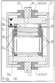
- Fig. 10 shows a design variant in which jointly or alternatively applicable measures are used to further reduce the likelihood of unwanted outer rollover.
- additional insulation measures are carried out in the outer region of the electrodes.
- the electrodes of the partial spark gaps may be provided with insulating material 25 in the outer region.
- the inner diameter of the isolated area is to be selected larger than the inner diameter of the spacers 21.
- the spacers 21 may further also be surrounded on the outer circumference with a ring of insulating material 26.
Description
Die Erfindung betrifft eine Überspannungsschutzeinrichtung auf Funkenstreckenbasis, umfassend mindestens zwei in einem druckdichten Gehäuse befindliche Hauptelektroden sowie mindestens eine Zündhilfselektrode, wobei im Gehäusevolumen eine Funktionsbaugruppe zum Reduzieren der Ansprechspannung der Funkenstrecke untergebracht ist, welche mit einer der Hauptelektroden und der Zündhilfselektrode in Verbindung steht. Der Trend bei der Entwicklung elektrischer und elektronischer Anlagen geht hin zu größerer Kompaktheit und geringeren Außenabmessungen. Gleichzeitig steigt aber die Empfindlichkeit gegenüber inneren und äußeren Überspannungen derartiger Anlagen. Darüber hinaus besteht der Wunsch und auch die Notwendigkeit nach einem möglichst störungsfreien Betrieb von elektrischen und elektronischen Einrichtungen, woraus sich neue Anforderungen an die Überspannungsschutztechnik ergeben.
So sind Überspannungsableiter mit reduzierter Ansprechspannung z. B. aus der
Damit das leistungsschwächere Feinschutzelement nicht zwangsweise bei einer solchen kompakten Anordnung überlastet wird, ergeben sich spezielle Anforderungen an den Blitzstromableiter bzw. das Grobschutzelement.The invention relates to a spark arrestor overvoltage protection device, comprising at least two main electrodes located in a pressure-tight housing and at least one auxiliary starting electrode, wherein a functional subassembly for reducing the response voltage of the spark gap is housed in the housing volume, which is in communication with one of the main electrodes and the auxiliary ignition electrode. The trend in the development of electrical and electronic systems is towards greater compactness and smaller external dimensions. At the same time, however, the sensitivity to inner and outer overvoltages of such systems is increasing. In addition, there is the desire and the need for a trouble-free operation of electrical and electronic devices, resulting in new requirements for the surge protection technology.
So are surge arresters with reduced operating voltage z. B. from the
So that the less powerful fine protection element is not necessarily overloaded in such a compact arrangement, there are special requirements for the lightning arrester and the coarse protection element.
Zur Realisierung dieser Aufgabenstellung wurde es bekannt, separate und extern an die Blitzstromableiter auf Funkenstreckenbasis angekoppelte, zum Teil recht komplexe Zündhilfen einzusetzen. Gemäß
Im Allgemeinen sind die Zündhilfen bei leistungsfähigen Überspannungsableitern für den Einsatz in Niederspannungsnetzen zwischen L und N bzw. auch N und PE als aktive Zündhilfen ausgeführt. Diese Zündhilfen generieren mit Hilfe eines Impulsübertragers eine hohe Zündspannung, durch welche bei einer typischen Dreielektroden-Funkenstreckenanordnung eine der Teilstrecken überschlagen wird.
Nachteilig bei einer solchen Lösung ist einerseits der zum Teil beachtliche Platzbedarf der Zündhilfe, die in der Regel aus einer Vielzahl von Bauelementen besteht, und andererseits die sich daraus ergebenden Störfaktoren.In general, the starting aids for high-performance surge arresters are designed for use in low-voltage networks between L and N or else N and PE as active ignition aids. These ignition aids generate a high ignition voltage with the aid of a pulse transformer, through which one of the partial sections is covered in a typical three-electrode spark gap arrangement.
The disadvantage of such a solution is on the one hand the sometimes considerable space requirement of the ignition aid, which usually consists of a plurality of components, and on the other hand, the resulting interference factors.
Der Platzbedarf dieser Zündeinrichtung schränkt bei den relativ geringen Abmessungen der Überspannungsableiter die konstruktiven Möglichkeiten für das Hauptfunktionselement, nämlich die eigentliche Funkenstrecke ein. Diese Einschränkung betrifft nicht nur das allgemein zur Verfügung stehende Volumen, sondern auch die Notwendigkeit der erforderlichen zusätzlichen Kontaktierung einer dritten Elektrode.The space requirement of this ignition device limits the design possibilities for the main functional element, namely the actual spark gap, given the relatively small dimensions of the surge arresters. This limitation not only concerns the volume generally available, but also the need for the necessary additional contacting of a third electrode.
Gegenüber einer einfachen Funkenstrecke ohne Zündhilfe ergibt sich derzeit eine Vielzahl an zusätzlichen Störquellen.
In der Funkenstrecke an sich muss nicht mehr nur die Funktion einer Trennstrecke gewährleistet werden, sondern die Funktion von zwei oder sogar drei Trennstrecken zwischen der Dreielektroden-Anordnung. Kommt es zu Schädigungen einer dieser Trennstrecken, besteht die Gefahr des Versagens des Ableiters. Hierbei kann es zu Schäden innerhalb der Funkenstrecke, aber auch der Zündhilfe selbst kommen. Dies kann insbesondere bei Überlastungen der Zündhilfe schnell zu einer Zerstörung des gesamten Ableiters und zu einer Gefährdung benachbarter Elemente führen. Selbiges ist jedoch nicht nur bei Beschädigungen innerhalb der Funkenstrecke, sondern auch bei Störungen wie Erschütterungen, Schwingungen, Abbrand, mangelhafte Installation und so weiter, Beschädigungen oder Korrosion der Kontakte der Zündeinrichtung mit den Hauptanschlüssen bzw. den Verbindern zur Funkenstrecke durchaus möglich.
Schlechte oder gealterte Kontaktstellen können außerhalb der Funkenstrecke zur Funkenbildung und letztendlich zum Außenüberschlag der Funkenstrecke führen.Compared to a simple spark gap without ignition aid is currently a variety of additional sources of interference.
In the spark gap itself, not only the function of a separation distance must be guaranteed, but the function of two or even three separation distances between the three-electrode arrangement. If damage occurs to one of these separation sections, there is a risk of the arrester failing. This can lead to damage within the spark gap, but also the ignition aid itself. This can quickly lead to destruction of the entire arrester and endangering adjacent elements, in particular when the ignition aid is overloaded. The same is not only for damage within the spark gap, but also in case of disturbances such as vibrations, vibrations, burn-off, poor installation and so on, damage or corrosion of the contacts of the ignition device with the main terminals and the connectors to the spark gap quite possible.
Bad or aged contact points can lead to sparking outside the spark gap and ultimately to outer spark gap.
Zwar gibt es durchaus Möglichkeiten, die Zündhilfen vor Überlastung zumindest teilweise zu schützen, jedoch bedeuten solche Maßnahmen, wie beispielsweise in der
Bei all den oben erläuterten Schwierigkeiten ist jedoch eine Zündhilfe für gewünschte tiefe Schutzpegel unabdingbar. Die allgemeine Reduktion des Abstands der Hauptelektroden, wie dies bei älteren Geräten des Standes der Technik der Fall war, ist bei modernen Ableitern nicht zielführend, da bei den üblichen geometrischen Bedingungen die erforderlichen Abstände nicht realisierbar sind bzw. diese eine deutliche Verschlechterung der erreichbaren Stoßstromwerte bedeuten.However, with all the difficulties discussed above, a priming aid for desired low levels of protection is indispensable. The general reduction of the distance of the main electrodes, as was the case with older devices of the prior art, is not expedient in modern arresters, as in the usual geometric conditions, the required distances are not feasible or this means a significant deterioration of the achievable surge currents ,
Bei der gattungsbildenden
Diese Anordnung hat jedoch den Nachteil, dass eine aktive Zündhilfe notwendig ist, wodurch der Platzbedarf und die Störanfälligkeit steigen. Diese sichere Funktionsweise aktiver Zündhilfen wird z.B. unter anderem durch Veränderung der Ansprechwerte und des Isolationswerts der einzelnen Trennstrecken gestört. Da diese Erscheinungen mit der Anzahl und der Höhe der Belastungen zunehmen, kann dies zur thermischen Überlastung bzw. sogar zum Versagen der Zündhilfe führen. Die Gefahr der thermischen Überlastung erhöht sich bei der oben erwähnten Anordnung zusätzlich durch die mangelnde Kühlung bzw. auch durch die Aufheizung infolge des Leistungsumsatzes in der Funkenstrecke und damit der Zündeinrichtung bei Belastungen.However, this arrangement has the disadvantage that an active ignition aid is necessary, whereby the space requirement and the susceptibility increase. This safe operation of active ignition aids is disturbed, inter alia, by changing the response values and the insulation value of the individual separation sections. As these phenomena increase with the number and magnitude of loads, this can lead to thermal overload or even failure of the ignition aid. The risk of thermal overload increases in the above-mentioned arrangement additionally by the lack of cooling or by the heating due to the power consumption in the spark gap and thus the ignition device under load.
Die Ausführung der Elektroden gemäß
Ebenfalls treten starke dynamische Belastungen zwischen den Elektroden beim Ansprechen der Funkenstrecke auf. Weitere Einschränkungen ergeben sich bei dieser Anordnung bei dem Einsatz in einer Funkenstrecke für Netzanwendungen. Im Gegensatz zur Trennfunkenstrecke müssen Netzfunkenstrecken Folgeströme im kA-Bereich beherrschen und lösen, wodurch nicht nur weitere und insbesondere länger einwirkende thermische Belastungen auftreten, sondern auch entsprechende Folgestrom löschende bzw. sogar Folgestrom begrenzende Maßnahmen realisiert werden müssen. Insbesondere hinsichtlich der Möglichkeiten zur Begrenzung des Netzfolgestroms in konventionellen Abmessungen der Überspannungsableiter für Netzanwendung, welche im Allgemeinen kleiner als Trennfunkenstrecken sind, führt eine Anordnung, wie in der
Also occur strong dynamic loads between the electrodes in response to the spark gap. Further restrictions arise in this arrangement when used in a spark gap for network applications. In contrast to the spark gap, network spark gaps must master and resolve secondary currents in the kA range, which not only causes further and in particular longer-acting thermal loads, but also corresponding consequential current-quenching or even consequential current-limiting measures have to be implemented. In particular, with regard to the possibilities of limiting the reticule current in conventional dimensions of the surge arresters for grid application, which are generally smaller than separating spark gaps, leads an arrangement as in
In der
Nachteilig ist bei dieser Lösung jedoch, dass die erste Funkenstrecke den thermischen Belastungen infolge des Lichtbogens und auch den Verunreinigungen infolge der Belastungen ausgesetzt ist. Das Einhalten von niedrigen und nahezu konstanten Ansprechspannungen wird hierdurch erschwert oder unmöglich. Bei einer räumlich getrennten Anordnung von erster und zweiter Funkenstrecke kann zwar die Einhaltung eines niedrigen Ansprechwerts gewährleistet werden, nachteilig ist jedoch, dass auf die Vorionisation der zweiten Funkenstrecke zur Herabsetzung der Ansprechspannung verzichtet werden muss. Dadurch muss der Spannungsabfall über der Impendanz bis zum Erreichen der unverminderten Ansprechspannung der zweiten Funkenstrecke erhöht werden. Sollen niedrigere Ansprechwerte der gesamten Funkenstrecke erreicht werden, wird die Wahl und die Leistungsfähigkeit der zweiten Funkenstrecke nach
A disadvantage of this solution, however, that the first spark gap the thermal stresses due to the arc and the impurities is exposed as a result of the stresses. The maintenance of low and almost constant threshold voltages is made difficult or impossible. Although in a spatially separated arrangement of the first and second spark gap, it is possible to ensure compliance with a low response value, it is disadvantageous, however, that the preionization of the second spark gap must be dispensed with in order to reduce the response voltage. As a result, the voltage drop across the impedance must be increased until reaching the undiminished response voltage of the second spark gap. If lower response values of the entire spark gap are to be achieved, the choice and performance of the second spark gap will diminish
Gemäß der Stapelfunkenstrecke für Mittel- und Hochspannungsanwendungen nach
Die Zündhilfe ist direkt mit den jeweiligen Hauptelektroden der Funkenstrecke verbunden. Sie besitzt keine dritte Hilfselektrode und es erfolgt keine direkte Entladung unmittelbar zwischen den Hauptelektroden. Die Art der Vorionisation beruht dort auf Teilentladungen, welche sich über beide Seite der Oberfläche eines vorhandenen Isolationsteils ausbreiten. Eine Möglichkeit zu einer Funkenentladung, wie sie üblicherweise bei modernen Niederspannungs-Ableitern genutzt wird, besteht nicht, da sich die Hilfselektroden der Zündhilfe auf entgegengesetzten Seiten des Isolators befinden. Diese Form der Zündhilfe ist bei hohen Potentialdifferenzen von mehreren kV für eine rasche Zündung ausreichend. Soll jedoch die Ansprechspannung <1kV betragen, ist eine derartige Ausführungsform einer Zündhilfe nicht effizient. Im übrigen ist die gesamte Zündhilfe schutzlos der Wirkung des Lichtbogens ausgesetzt, was sowohl zu Störungen bei deren Funktion als auch zur gänzlichen Zerstörung führen kann.According to the stack spark gap for medium and high voltage applications after
The ignition aid is connected directly to the respective main electrodes of the spark gap. It has no third auxiliary electrode and there is no direct discharge directly between the main electrodes. The type of preionization is based there on partial discharges, which spread over both sides of the surface of an existing insulation part. One possibility for a spark discharge, as is commonly used in modern low-voltage arresters, does not exist because the auxiliary electrodes of the ignition aid are located on opposite sides of the insulator. This form of ignition aid is sufficient at high potential differences of several kV for rapid ignition. However, if the response voltage is <1 kV, such an embodiment of a starting aid is not efficient. Moreover, the entire Zündhilfe is defenseless the effect of the arc exposed, which can lead both to disruption in their function as well as to complete destruction.
Es sind Ausführungen mit Hilfsfunkenstrecken bekannt geworden, bei denen eine Funkenentladung möglich ist. Bei derartigen Anordnungen wird die Entladung von der Hilfsfunkenstrecke, bei welcher der Stromfluss durch verschiedene Maßnahmen begrenzt wird, auf die Hauptelektroden übergeben. Bei derartigen Lösungen müsste unabhängig von der Verzugszeit bis zum Zünden der Hauptfunkenstrecke jedoch bereits die Hilfsfunkenstrecke mit einer geeigneten Zündhilfe ausgestattet sein, um selbst eine Ansprechspannung von z. B. <1kV zuverlässig zu halten.There are known versions with auxiliary spark gaps, in which a spark discharge is possible. In such arrangements, the discharge from the auxiliary spark gap, in which the current flow is limited by various measures, is transferred to the main electrodes. In such solutions, however, the auxiliary spark gap would have to be equipped with a suitable ignition aid regardless of the delay time to ignite the main spark gap to even a response voltage of z. B. <1kV to keep reliable.
Die
Zusätzlich wird das Zündelement bei dieser Lösung während der gesamten Lichtbogendauer, bestehend aus Impuls- und Folgestrom, infolge der direkt parallelen Anordnung zu den Hauptelektroden und somit zur gesamten Lichtbogenspannung mit einem Stromfluss belastet, wodurch der elektrische und thermische Stress des Zündelements und u. U. auch des spannungsschaltenden Elements groß ist. Eine weitere Voraussetzung für die Grundfunktion gemäß
Die eingesetzte Feder zur Kontaktherstellung und Nachführung des Zündelements kann eventuell bei Abbrand bzw. Abbruch der Spitze des Zündelements dieses nachführen. Jedoch kann die Feder weder einen Komplettbruch des Zündelements nach Veränderungen der Kontaktstelle infolge der Bildung von Schmelze an der Elektrode bzw. an dem Zündelement oder die Ablagerungen von Verunreinigungen im Kontaktbereich vermeiden. Selbstverständlich muss auch die Feder vor Abbrandprodukten und den thermischen und dynamischen Belastungen durch den Lichtbogen geschützt werden.
Bei einer geringen oder auch nur zeitlich verzögerten Funkenbildung erhöht sich jedoch die Zündverzugszeit der Hauptfunkenstrecke. Einerseits kann sich dadurch die elektrische Belastung des spannungsschaltenden Elements und auch des Zündelements deutlich erhöhen, andererseits steigt die Spannung über dem Zündelement und somit über der gesamten Funkenstrecke stark an. Dies gefährdet auch die zu schützenden Elemente und die gewünschten niedrigen Restspannungswerte des Blitzstromableiters.The
In addition, the ignition element in this solution during the entire arc duration, consisting of pulse and follow current, due to the direct parallel arrangement to the main electrodes and thus the entire arc voltage with a current flow, whereby the electrical and thermal stress of the ignition element and u. U. also the voltage-switching element is large. Another requirement for the basic function according to
The inserted spring for making contact and tracking of the ignition element may possibly track in case of burning or demolition of the tip of the ignition element. However, the spring can avoid neither a complete break of the ignition element after changes in the contact point due to the formation of melt on the electrode or on the ignition element or the deposits of impurities in the contact area. Of course, the spring must also be protected from burn-off products and the thermal and dynamic stresses caused by the arc.
With a small or even delayed sparking, however, increases the Zündverzugszeit the main spark gap. On the one hand, this can significantly increase the electrical load on the voltage-switching element and also of the ignition element; on the other hand, the voltage across the ignition element and thus over the entire spark gap increases sharply. This also endangers the elements to be protected and the desired low residual voltage values of the lightning arrester.
Ein weiterer Nachteil der zitierten Lösung besteht darin, dass der Abstand der Hauptelektroden unmittelbar mit der Länge des Zündelements verbunden ist. Insbesondere für Netzfunkenstrecken ist jedoch häufig ein relativ großer Hauptelektroden-Abstand vorteilhaft. Mit zunehmendem Abstand der Hauptelektroden steigt jedoch auch die Ansprechspannung zwischen den Elektroden. Das heißt, bei höheren Abständen muss eine stärkere Vorionisation zwischen den Hauptelektroden erfolgen, damit es zum Überschlag bei den angestrebten niedrigen Spannungen kommen kann. Ebenso verlängert sich die Strecke, an welcher der Funke von der schlechten Kontaktstelle entlang wandern muss, bis er die andere Hauptelektrode erreicht. Dies schränkt zudem auch, wie bereits erwähnt, die Wahl der üblichen Mittel zur Folgestromlöschung bzw. -begrenzung ein.Another disadvantage of the cited solution is that the distance of the main electrodes is directly connected to the length of the ignition element. In particular, for network spark gaps, however, a relatively large main electrode spacing is often advantageous. However, as the distance between the main electrodes increases, so does the response voltage between the electrodes. That is, at higher distances, a greater preionization between the main electrodes must be made, so that it can lead to the rollover at the desired low voltages. Likewise, the distance at which the spark must travel from the bad pad lengthens until it reaches the other major electrode. This also restricts, as already mentioned, the choice of the usual means for the sequence current deletion or limitation.
Die Funkenstreckenanordnung nach
Im übrigen bestehen die Zündhilfen aus einer Vielzahl von Bauelementen, welche die Aufgabe des Feinschutzes übernehmen sollen. Dies bedingt jedoch verhältnismäßig große und leistungsfähige Bauelemente, wodurch eine Integration in die Funkenstrecke erschwert wird. Die Aufgabe des Feinschutzes bedingt jedoch auch einen verhältnismäßig hohen Leistungsumsatz und eine zusätzliche thermische Belastung.
Bei der passiven Zündhilfe, welche vorteilhafterweise nur aus wenigen Bauelementen besteht, würde sich zwar der Platzbedarf reduzieren, jedoch bleibt das Problem des Leistungsumsatzes bei der Realisierung des Feinschutzes bestehen. Nachteilig ist bei der
Moreover, the Zündhilfen consist of a variety of components, which should take over the task of fine protection. However, this requires relatively large and powerful components, whereby integration into the spark gap is difficult. However, the task of fine protection also requires a relatively high power consumption and an additional thermal load.
In the passive ignition aid, which advantageously consists of only a few components, although the space requirement would reduce, but the problem of power conversion remains in the realization of fine protection. The disadvantage is in the
Auch die Integration eines PTC-Elements in die Funkenstrecke ist problematisch. Derartige PTC-Elemente erwärmen sich aufgrund ihrer Funktionsweise um bis zu mehreren 100 K. Eine derartige Erwärmung stellt jedoch sehr hohe Anforderungen an die Belastbarkeit der Isolationselemente. Zusätzlich ist eine derartige Anwendung eines PTC-Elements dadurch erschwert, dass dieses, um die Funktionsweise der Funkenstrecke wieder sicherzustellen, relativ schnell nach Belastung abzukühlen ist. Eine solche Abkühlung würde jedoch durch eine Kapselung erschwert werden.
Aus dem Vorgenannten ist es daher Aufgabe der Erfindung, eine Überspannungsschutzeinrichtung auf Funkenstreckenbasis, insbesondere für Niederspannungs-Anwendungen, umfassend mindestens zwei in einem druckdichten Gehäuse befindliche Hauptelektroden sowie mit mindestens einer Zündhilfselektrode anzugeben, welche mögliche Störquellen zwischen Zündhilfe und Funkenstrecke vermeidet und die prinzipiell bei allen bekannten Verfahren zur Folgestromlöschung, Folgestrombegrenzung oder aber auch der Vermeidung von Folgeströmen bei Funkenstrecken einsetzbar ist. Die anzugebende Lösung soll also universelle Applikationen, und zwar unabhängig von der konkreten Elektrodengeometrie gestatten.
Die Lösung der Aufgabe der Erfindung erfolgt mit einer Überspannungsschutzeinrichtung auf Funkenstreckenbasis gemäß der Merkmalskombination nach Patentanspruch 1, wobei die Unteransprüche mindestens zweckmäßige Ausgestaltungen und Weiterbildungen darstellen.
Gemäß dem Grundgedanken der Erfindung wird von einer vereinfachten Zündhilfe ausgegangen, welche zumindest aus einem spannungsschaltenden Element, einer Impedanz und einer Trennstrecke besteht. Die vereinfachte Zündhilfe ist zwischen zwei Hauptelektroden sowie vollständig im druckfesten Gehäuse der Überspannungsschutzeinrichtung, d.h. in die Funkenstrecke selbst integriert und wird Bestandteil dieser. Tritt an einer solchen Anordnung eine Überspannung auf, die die Summe der Ansprechspannungen des Schaltelements und der Trennstrecke der Reihenschaltung übersteigt, so spricht die Zündhilfe an, wodurch ein Strom über das spannungsschaltende Element, die Impedanz und die zugehörige Trennstrecke von der ersten Hauptelektrode zur zweiten Hauptelektrode fließt. Durch den Lichtbogen, welcher diese vorerwähnte Trennstrecke überbrückt, werden sofort beim Ansprechen der Zündhilfe Ladungsträger in die Funkenstrecke eingebracht, welche eine sofortige Ionisation der Trennstrecke zwischen den beiden Hauptelektroden bewirkt, wodurch die Spannungsfestigkeit dieser Trennstrecke reduziert wird und es infolge des mit der Stromstärke ansteigenden Spannungsabfalls über der Impedanz es schließlich zum Überschreiten der nun reduzierten Spannungsfestigkeit der Trennstrecke zwischen den beiden Hauptelektroden und somit zur Zündung der Funkenstrecke kommt.The integration of a PTC element in the spark gap is problematic. Such PTC elements heat up due to their operation by up to several 100 K. However, such heating places very high demands on the load capacity of the insulation elements. In addition, such application of a PTC element is made more difficult by the fact that, in order to ensure the functioning of the spark gap, it has to be cooled relatively quickly after loading. However, such a cooling would be hampered by encapsulation.
From the foregoing, it is therefore an object of the invention to provide a spark arrester overvoltage protection device, in particular for low-voltage applications comprising at least two located in a pressure-tight housing main electrodes and at least one auxiliary ignition, which avoids possible sources of interference between ignition aid and spark gap and the principle in all known method for subsequent current deletion, follow current limiting or even the avoidance of subsequent currents in spark gaps can be used. The solution to be specified should therefore allow universal applications, regardless of the specific electrode geometry.
The object of the invention is achieved with a surge protection device on spark gap basis according to the combination of features according to
According to the basic idea of the invention, a simplified starting aid is assumed which consists of at least one voltage-switching element, an impedance and an isolating distance. The simplified ignition aid is integrated between two main electrodes and completely in the pressure-resistant housing of the overvoltage protection device, ie in the spark gap itself and is part of this. Occurs on such an arrangement, an overvoltage that exceeds the sum of the operating voltages of the switching element and the separation distance of the series circuit, so the ignition aid, whereby a current through the voltage switching element, the impedance and the associated separation distance from the first main electrode to the second main electrode flows. By the arc, which bridges this aforementioned separation distance are immediately at Response of the priming charge carriers placed in the spark gap, which causes an immediate ionization of the separation distance between the two main electrodes, whereby the dielectric strength of this separation distance is reduced and it due to the current increasing voltage drop across the impedance it finally to exceed the now reduced withstand voltage of the separation path between the two main electrodes and thus comes to the ignition of the spark gap.
Durch die Integration in das druckfeste Gehäuse der Funkenstrecke, jedoch außerhalb des Brennraums des Lichtbogens, werden alle externen Anschlussprobleme der Zündeinrichtung an die Funkenstrecke beseitigt.
Die druckfeste Kapselung ist für das Beherrschen von Drücken bis zu mehreren 10 bar infolge der Belastungen der Funkenstrecke bei Blitzen und Netzfolgeströmen ausgelegt.
Bei einer möglichen Überlastung der Zündhilfe wird das Schadenspotential somit wesentlich durch die druckfeste Kapselung der Funkenstrecke eingegrenzt. Hierdurch entfallen auch zusätzliche Schutzmaßnahmen der Zündhilfe selbst, wie z. B. Sicherungen oder Ähnliches. Eine eventuell gewünschte Bewertung des Zustands des Ableiters ist ebenfalls stark erleichtert, da nur die Gesamtfunktion, messbar an den äußeren Klemmen der Funkenstrecke, und nicht einzelne Bauelemente, Verbindungen und Komponenten überwacht werden müssen.By integrating into the pressure-resistant housing of the spark gap, but outside the combustion chamber of the arc, all external connection problems of the ignition device are eliminated at the spark gap.
The flameproof enclosure is designed for the control of pressures up to several 10 bar as a result of the strains of the spark gap during lightning and line flow.
In case of a possible overload of the ignition aid, the damage potential is thus essentially limited by the flameproof enclosure of the spark gap. This also eliminates additional protective measures of the ignition itself, such. B. fuses or the like. A possibly desired evaluation of the state of the arrester is also greatly facilitated, since only the overall function, measurable at the outer terminals of the spark gap, and not individual components, connections and components must be monitored.
Erfindungsgemäß ist also die Zündhilfs-Funktionsbaugruppe zum gezielten Reduzieren der Ansprechspannung der Funkenstrecke aus einer vollständig in das druckdichte Gehäuse integrierten, außerhalb des Lichtbogen-Brennraums befindlichen Reihenschaltung eines spannungsschaltenden Elements, einer Impedanz und einer Trennstrecke gebildet, wobei die Trennstrecke durch den Abstand der Zündhilfselektrode zur nächstliegenden Hauptelektrode definiert ist.According to the invention, the Zündhilfs function module for selectively reducing the operating voltage of the spark gap from a fully integrated into the pressure-tight housing, located outside the arc combustion chamber series connection of a voltage-switching element, an impedance and a separation path is formed, wherein the separation distance by the distance of the auxiliary ignition electrode nearest main electrode is defined.
Das spannungsschaltende Element kann beispielsweise ein Gasableiter sein. Ebenso besteht die Möglichkeit, das spannungsschaltende Element als Suppressordiode, Thyristor, Varistor und/oder als definiert abbrandfeste Luft-oder Gleitfunkenstrecke auszubilden.The voltage switching element may for example be a gas arrester. It is also possible to form the voltage-switching element as a suppressor diode, thyristor, varistor and / or as a defined erosion-resistant air or sliding spark gap.
Die Zündhilfselektrode kann selbst impedanzbehaftet ausgeführt sein und einen komplexen Widerstand besitzen.The auxiliary ignition electrode can itself be designed impedance-related and have a complex resistance.
Bevorzugt reicht die Zündhilfselektrode partiell in den Lichtbogen-Brennraum hinein oder befindet sich in diesem.
Die Zündhilfselektrode kann aus einem leitfähigen Kunststoff oder einem Kunststoff mit leitfähigen Zusätzen, wie z. B. leitfähigen Fasern bestehen.Preferably, the auxiliary ignition electrode extends partially into the arc combustion chamber or is located in this.
The auxiliary ignition electrode may be made of a conductive plastic or a plastic with conductive additives, such as. B. conductive fibers.
Die Impedanz wiederum besteht aus einem Material mit nichtlinearem oder linearem Widerstandsverlauf.The impedance in turn consists of a material with a nonlinear or linear resistance profile.
Ebenso kann die Impedanz aber auch aus einem leitfähigen Kunststoff oder einer leitfähigen Keramik bestehen.Likewise, however, the impedance can also consist of a conductive plastic or a conductive ceramic.
Auch ist eine Ausführungsform der Impedanz als diskretes Bauelement, z. B. Widerstand, Varistor oder Kapazität im Sinne der Erfindung liegend.Also, an embodiment of the impedance as a discrete component, for. B. resistance, varistor or capacitance lying within the meaning of the invention.
Die Zündhilfselektrode ist gegenüber der Hauptelektrode isoliert, wobei die Ansprechspannungen der sich zu den Hauptelektroden jeweils ergebenden Teilstrecken unterschiedlich gewählt werden.The auxiliary ignition electrode is insulated from the main electrode, wherein the response voltages of each of the main electrodes resulting sub-sections are chosen differently.
Die Ansprechspannung e1 der ersten Hauptelektrode zur Zündhilfselektrode ist viel größer als die Ansprechspannung der weiteren Trennstrecke e2 gewählt.The response voltage e 1 of the first main electrode to the auxiliary ignition electrode is much larger than the response voltage of the further separation distance e 2 selected.
Zur Reduzierung der Ansprechspannung der Trennstrecke e2 ist diese als dünne, abbrandfeste Isolierfolie, als abbrandfeste Lackbeschichtung oder sonstige dünne Isolierschicht ausgebildet.
Bei einer weiteren bevorzugten Ausführungsform weist die Überspannungsschutzeinrichtung Mittel zum Beströmen des Lichtbogens mit Hartgas auf.To reduce the response voltage of the separation distance e 2 this is designed as a thin, erosion-resistant insulating film, as erosion-resistant paint coating or other thin insulating layer.
In a further preferred embodiment, the overvoltage protection device has means for flowing the arc with hard gas.
Zum Erzeugen des Hartgases umgibt hartgasabgebendes Material mindestens Abschnitte des Lichtbogen-Brennraums, wobei das hartgasabgebende Material zusätzlich leitfähige Eigenschaften aufweist, um das Potential einer der Hauptelektroden bis an die Trennstrecke der Zündhilfselektrode heranzuführen.For producing the hard gas, hard-gas-releasing material surrounds at least portions of the arc-combustion chamber, wherein the hard-gas-emitting material additionally has conductive properties to the potential of one of Main electrodes should be brought to the separation distance of the auxiliary ignition electrode.
Bei der Hartgas-Ausführungsvariante verhindert eine Druckausgleichsöffnung, dass sich über die Zeit ein unerwünschter Druckanstieg akkumuliert.In the hard gas embodiment, a pressure equalization port prevents accumulation of an undesirable increase in pressure over time.
Die Druckausgleichsöffnung kann durch das Gehäuse oder durch Elektrodenmaterialien gebildet werden, welche mindestens teilweise gasdurchlässig sind.
Hierfür können Abschnitte des Gehäuses aus einem porösen Polymermaterial, poröser Keramik oder entsprechend porösem Metall bestehen.The pressure equalization port may be formed by the housing or by electrode materials which are at least partially gas permeable.
For this purpose, portions of the housing may consist of a porous polymer material, porous ceramic or correspondingly porous metal.
Die Überspannungsschutzeinrichtung kann bei einer weiteren Ausführungsform Mittel zur Restspannungsbegrenzung aufweisen.In a further embodiment, the overvoltage protection device can have residual voltage limiting means.
Hier besteht insbesondere die Möglichkeit, das leitfähige, hartgasabgebende Material, welches elektrisch mit einer der Hauptelektroden in Verbindung steht, in einer definierten Geometrie sowie mit definierten elektrischen Eigenschaften auszuführen, so dass die zielgerichtete Beeinflussung des Verlaufs und der Höhe der Restspannung realisierbar ist.In particular, it is possible here to carry out the conductive, hard-gas-emitting material, which is electrically connected to one of the main electrodes, in a defined geometry and with defined electrical properties, so that the targeted influencing of the course and the height of the residual voltage can be realized.
Bevorzugt ist der Widerstand des hartgasabgebenden Materials gegenüber der Impedanz der Reihenschaltung des Funktionselements niedriger.Preferably, the resistance of the hard gas-emitting material to the impedance of the series connection of the functional element is lower.
Das leitfähige, hartgasabgebende Material trägt während der Belastung mit Stoßstrom als auch mit Folgeströmen einen Teil des jeweils fließenden Gesamtstroms, so dass sich die Zuverlässigkeit der erfindungsgemäßen Einrichtung und deren Langzeitstabilität erhöht.The conductive, hard gas-emitting material carries during the load with surge current as well as with subsequent currents part of each flowing total current, so that increases the reliability of the device according to the invention and its long-term stability.
Der Stromanteil, welcher vom leitfähigen, hartgasabgebenden Material übernommen wird, ist über das Verhältnis des Widerstands dieses Materials zum Widerstandswert des Lichtbogens quasi einstellbar.The proportion of current which is taken over by the conductive, hard-gas-emitting material is virtually adjustable by the ratio of the resistance of this material to the resistance value of the arc.
Bevorzugt ist der mittlere Wert des Widerstands des leitfähigen, hartgasabgebenden Materials größer gewählt, als der durchschnittliche, mittlere Widerstandswert des Lichtbogens ist.Preferably, the average value of the resistance of the conductive, hard gas-emitting material is chosen to be greater than the average, mean resistance value of the arc.
Zum Schutz vor thermischen und/oder mechanischen Belastungen kann bei einer Ausgestaltung der Erfindung das spannungsschaltende Element und/ oder die diskrete Impedanz in eine der Hauptelektroden integriert werden. Hierfür kann eine der Hauptelektroden einen von außen zugänglichen Hohlraum aufweisen, wodurch auch, wenn nötig, eine Austauschbarkeit des spannungsschaltenden Elements gewährleistet ist.In order to protect against thermal and / or mechanical stresses, in one embodiment of the invention, the voltage-switching element and / or the discrete impedance can be integrated into one of the main electrodes. For this purpose, one of the main electrodes have an externally accessible cavity, whereby also, if necessary, an interchangeability of the voltage-switching element is ensured.
Das spannungsschaltende Element ist in den Hohlraum einpolig isoliert eingesetzt, wobei der Hohlraum ein Innengewinde zur Aufnahme einer, das eingesetzte spannungsschaltende Element kontaktierenden leitfähigen Schraube aufweist.The voltage-switching element is inserted in a single-pole insulated manner in the cavity, wherein the cavity has an internal thread for receiving a conductive screw contacting the inserted voltage-switching element.
In einer weiteren Ausführungsform der Erfindung liegt das zum Lichtbogen-Brennraum reichende Ende der Zündhilfselektrode im wesentlichen auf gleicher Höhe des in den Brennraum hineinreichenden Endes derjenigen Hauptelektrode, welche der ersten Trennstrecke zugehörig ist.In a further embodiment of the invention, the end of the auxiliary ignition electrode reaching the arc combustion chamber lies essentially at the same level as the end of the main electrode which reaches into the combustion chamber and is associated with the first separation zone.
Auch kann die Zündhilfselektrode seitlich versetzt und/oder bezogen auf den Lichtbogen-Hauptbrennraum zurückgesetzt zum Schutz dieser angeordnet werden.Also, the Zündhilfselektrode laterally offset and / or relative to the arc main combustion chamber set back to protect this can be arranged.
Über ein ergänzendes spannungsschaltendes Element, welches außerhalb der druckdichten Kapselung befindlich ist, kann eine Einstellung oder Anpassung der Ansprechspannung der Überspannungsschutzeinrichtung erfolgen.Via a supplementary voltage-switching element, which is located outside the pressure-tight enclosure, an adjustment or adjustment of the operating voltage of the overvoltage protection device can take place.
Grundsätzlich ist die vorgestellte Überspannungsschutzeinrichtung auch als Kombination aus einer triggerbaren Teilfunkenstrecke hoher Ansprechspannung und mindestens einer nachgeordneten Teilfunkenstrecke niedriger Ansprechspannung realisierbar.In principle, the presented overvoltage protection device can also be implemented as a combination of a triggerable partial spark gap high response voltage and at least one downstream partial spark gap low response voltage.
Bei dieser Ausführungsform können die Teilfunkenstrecken Mittel zur internen Potentialsteuerung aufweisen.
Die Teilfunkenstrecken sind über Distanzhalter mechanisch fixiert und verbunden.
Die Distanzhalter können aus einem leitfähigen, feldsteuernden Material bestehen.In this embodiment, the partial spark gaps may include means for internal potential control.
The partial spark gaps are mechanically fixed and connected via spacers.
The spacers may consist of a conductive, field-controlling material.
Die Distanzhalter und die Elektroden der Teilfunkenstrecken können bei einer Ausführungsform der Erfindung eine Ummantelung besitzen, wobei die Ummantelung eine einseitig elektrisch angeschlossene Schirmung zur gezielten Potentialverzerrung umfasst oder als solche selbst ausgebildet ist.In one embodiment of the invention, the spacers and the electrodes of the partial spark gaps may have a sheath, wherein the sheath comprises a shield which is electrically connected on one side for targeted potential distortion or is designed as such itself.
Der Abstand der Elektroden, welche die Teilfunkenstrecke mit Zündhilfselektrode bilden, ist bevorzugt größer gewählt als der Abstand der Elektroden, die die jeweils folgenden Teilfunkenstrecken definieren.The distance of the electrodes which form the partial spark gap with auxiliary ignition electrode is preferably chosen to be greater than the spacing of the electrodes which define the respectively following partial spark gaps.
Der Distanzhalter kann für die nicht durch die Zündhilfselektrode triggerbare Teilfunkenstrecke als ein integrales Bauteil im Sinne der Fertigungsrationalisierung und leichteren Montage ausgeführt werden.The spacer can be performed for the non-triggerable by the auxiliary ignition partial spark gap as an integral component in terms of manufacturing rationalization and easier installation.
Zur Vermeidung eines elektrischen Überschlags außerhalb des Lichtbogen-Brennraums sind zusätzliche Isolierabschnitte oder Isoliermaterialien, bevorzugt im äußeren Bereich der Elektroden der Teilfunkenstrecke vorgesehen oder dort angeordnet.To avoid an electrical flashover outside of the arc combustion chamber additional insulating sections or insulating materials, preferably provided in the outer region of the electrodes of the partial spark gap or arranged there.
Die Distanzhalter weisen auf ihrer vom Lichtbogen-Brennraum entfernten Seite eine Isolationsbeschichtung oder Isolationsumhüllung auf, was sich als ergänzende Maßnahme zur Vermeidung unerwünschter Überschläge darstellt.The spacers have on their side remote from the arc combustion chamber on an insulation coating or insulation sheath, which is a complementary measure to avoid unwanted flashovers.
Es besteht die Möglichkeit, die erste, triggerbare Teilfunkenstrecke durch einen Gasableiter zu ersetzen, welcher die Ansprechspannung der Gesamtanordnung bestimmt, ohne dass hierdurch der Grundgedanke der Erfindung verlassen wird.It is possible to replace the first, triggerable partial spark gap by a gas discharge tube, which determines the response voltage of the overall arrangement, without departing from the basic idea of the invention.
Ganz grundsätzlich kann die erfindungsgemäße Funkenstrecke als Hörnerfunkenstrecke oder aber auch als Stapelfunkenstrecke ausgeführt werden.In principle, the spark gap according to the invention can be embodied as a horn spark gap or else as a stack spark gap.
Die Erfindung soll nachstehend anhand von Ausführungsbeispielen sowie unter Zuhilfenahme von Figuren näher erläutert werden.The invention will be explained below with reference to exemplary embodiments and with the aid of figures.
Hierbei zeigen:
- Fig. 1
- eine Prinzip-Schnittdarstellung durch eine in einer gekapselten Funkenstrecke befindlichen Zündhilfe;
- Fig. 2
- eine Ausführungsform ähnlich
Fig. 1 , jedoch mit zusätzlichem hartgasabgebenden Material, welches den Lichtbogen-Brennraum umgibt; - Fig. 3
- eine weitere Ausführungsform der Überspannungsschutzeinrichtung ähnlich wie in
Fig. 2 dargestellt, jedoch mit variierter Heranführung des Potentials der Hauptelektrode an die Zündhilfselektrode; - Fig. 4
- eine Darstellung einer Überspannungsschutzeinrichtung mit einem spannungsschaltenden Element, integriert in eine der Hauptelektroden;
- Fig. 5
- eine Ausführungsform mit spezieller höhenmäßiger Zuordnung einer der Hauptelektroden zur Zündhilfselektrode;
- Fig. 6
- eine weitere Ausführungsform der Zuordnung von Zündhilfselektrode und benachbarter Hauptelektrode;
- Fig. 7
- eine Darstellung mit einem spannungsschaltenden Element außerhalb der druckfesten Kapselung der Funkenstrecke;
- Fig. 8
- eine Funkenstrecke, umfassend mehrere Teilfunkenstrecken;
- Fig. 9
- eine Darstellung ähnlich
Fig. 8 , jedoch mit einem gemeinsamen Distanzhalter für die nicht triggerbaren Teilfunkenstrecken und - Fig. 10
- eine Darstellung einer Funkenstrecke ähnlich den
Fig. 8 und9 , jedoch mit zusätzlichen Maßnahmen zur Isolation zum Zweck des Vermeidens von unerwünschten äußeren Durchschlägen.
- Fig. 1
- a schematic cross-sectional view through a located in an encapsulated spark gap ignition aid;
- Fig. 2
- an embodiment similar
Fig. 1 but with additional hard gas emitting material surrounding the arc combustion chamber; - Fig. 3
- a further embodiment of the overvoltage protection device similar to in
Fig. 2 illustrated, but with varied approach of the potential of the main electrode to the auxiliary ignition electrode; - Fig. 4
- an illustration of an overvoltage protection device with a voltage-switching element integrated in one of the main electrodes;
- Fig. 5
- an embodiment with special elevational assignment of one of the main electrodes to the auxiliary ignition electrode;
- Fig. 6
- a further embodiment of the assignment of Zündhilfselektrode and adjacent main electrode;
- Fig. 7
- a representation with a voltage-switching element outside the flameproof enclosure of the spark gap;
- Fig. 8
- a spark gap comprising a plurality of partial spark gaps;
- Fig. 9
- a representation similar
Fig. 8 , but with a common spacer for the non-triggerable partial spark gaps and - Fig. 10
- a representation of a spark gap similar to the
Fig. 8 and9 but with additional insulation measures for the purpose of avoiding unwanted external breakdowns.
Die passive Zündhilfe 100 entsprechend
Die Zündhilfe 100 besteht aus einem spannungsschaltenden Element 4, bevorzugt einem Gasableiter, wobei jedoch auch Suppressordioden, Thyristoren, Varistoren, definiert abbrandfeste Trennstrecken oder eine Kombination dieser Elemente geeignet sind. Weiterhin weist die Zündhilfe 100 eine impedanzbehaftete Zündhilfselektrode 3 auf. Es besteht auch die Möglichkeit, dass eine diskrete Impedanz 3a als separates Element vorhanden ist.The
Als Impedanz 3a sind Elemente bzw. Materialien wie Kunststoffe oder Keramiken mit linearen, aber auch mit nichtlinearen Widerständen bzw. Kennlinien geeignet. Beim Einsatz einer diskreten Impedanz 3a kann diese z. B. als Widerstand, als Varistor, als Kapazität oder aber auch aus Materialien mit entsprechender Charakteristik derartiger Bauelemente ausgeführt werden.As
Die Zündhilfselektrode oder Zündelektrode 3 ist gegenüber den beiden Hauptelektroden 1 und 2 isoliert. Die Ansprechspannungen der sich ergebenden Teilfunkenstrecken e1 und e2 sind jedoch unterschiedlich ausgelegt.The auxiliary ignition electrode or
Die Ansprechspannung der Strecke e1, d.h. der Hauptelektrode 1 zur Zündhilfselektrode 3 ist viel größer als die Ansprechspannung der Strecke e2, gebildet durch den Abstand der Hauptelektrode 2 zur Zündhilfselektrode 3.The response voltage of the distance e 1 , ie the
Die Ansprechspannung der Strecke e1 ist mindestens gleich, aber im allgemeinen höher als die Ansprechspannung des spannungsschaltenden Elements 4 der Zündhilfe 100.
Die Ansprechspannung der Strecke e2 ist hingegen höchstens gleich, aber im Allgemeinen niedriger als die Ansprechspannung des spannungsschaltenden Elements 4 der Zündhilfe 100.The response voltage of the distance e 1 is at least equal, but generally higher than the response voltage of the voltage-switching
On the other hand, the response voltage of the distance e 2 is at most equal but generally lower than the response voltage of the voltage-switching
Auf diese Weise ist gewährleistet, dass die Ansprechspannung des gesamten Ableiters im wesentlichen durch die Ansprechspannung des spannungsschaltenden Elements 4 bestimmt wird und damit unabhängig von den üblichen geometrischen Bedingungen der Hauptfunkenstrecke gewählt werden kann. Vorteilhafterweise sind alle für das Ansprechverhalten funktionsrelevanten Teile nicht der direkten Lichtbogeneinwirkung ausgesetzt. Einzig ein Ende der Zündhilfselektrode 3, welche bevorzugt selbst impedanzbehaftet, z. B. als leitfähigem Kunststoff ausgeführt werden kann, befindet sich partiell im Lichtbogen-Brennraum und wird isoliert gegenüber den beiden Hauptelektroden 1, 2 ausgeführt.In this way, it is ensured that the response voltage of the entire arrester is essentially determined by the response voltage of the voltage-switching
Wenn die Zündhilfselektrode 3 nicht aus einem impedanzbehafteten Material, sondern aus einem niederohmigen Material, z. B. Kupfer oder Ähnlichem ausgeführt ist, wird, wie bereits erwähnt, eine separate Impedanz 3a eingesetzt, die dann vollständig außerhalb der direkten Lichtbogeneinwirkung befindlich ist.If the
Der im Lichtbogen-Brennraum unvermeidbare Abbrand aller Teile kann die Zündhilfselektrode 3 nur partiell schädigen. Da der Lichtbogenabbrand im gesamten Brennraum der Funkenstrecke allseitig erfolgt, werden alle den Brennraum begrenzenden Teile, also auch die Zündhilfselektrode 3, mit ihren angrenzenden Isolationsteilen nach und nach abgebrannt.
Hierdurch ist sichergestellt, das die geometrischen Proportionen aller Bauteile nach jeder Belastung weitestgehend gleich bleiben.
Infolge eines ungleichmäßigen Abbrands bzw. infolge von Verunreinigungen kann es aber auch bei dieser Geometrie zur Schädigung oder zum Überbrücken der kurzen Isolationsstrecke e2 kommen. Insbesondere bei nahezu allen aktiven externen Zündhilfen würde dies quasi zum Kurzschluss des Impulsübertragers und somit zum Versagen oder zur Überlastung der Zündhilfe führen. Bei der hier vorgeschlagenen Gestaltung gemäß Ausführungsbeispiel ist dies jedoch nicht der Fall. Die entstehenden Verunreinigungen als auch die in der Regel nur partiellen Kontaktbrücken, welche durch Schmelzerscheinungen gebildet werden und aufgrund der Auslegung der Bauteile nur geringfügig sind, besitzen einen vergleichsweise hohen Widerstand und werden durch einen geringen Stromfluss beseitigt.The unavoidable burning of all parts in the arc combustion chamber can damage the
This ensures that the geometric proportions of all components remain largely the same after each load.
As a result of uneven burning or as a result of contamination, however, damage to or bridging of the short insulation gap e 2 may also occur in this geometry. In particular, in almost all active external ignition aids this would virtually for short circuit of the pulse transformer and thus lead to failure or overloading of the ignition aid. However, this is not the case with the design proposed here according to the exemplary embodiment. The resulting impurities as well as the usually only partial contact bridges, which are formed by melting phenomena and due to the design of the components are only slightly, have a relatively high resistance and are eliminated by a low current flow.
Die elektrischen Parameter der in die Funkenstrecke integrierten Bauelemente sind einerseits durch die geometrischen Abmessungen vorgegeben. Andererseits wird aber der Leistungsumsatz auch zugunsten einer einfachen Konstruktion der Kontaktstellen und auch der thermischen Belastung der Isolationsstrecken begrenzt. Die Leistungsfähigkeit der Zündhilfe bei der vorliegenden Ausführungsform beschränkt sich auf kleine Impulsleistungen.The electrical parameters of the components integrated in the spark gap are predetermined on the one hand by the geometric dimensions. On the other hand, the power conversion is also limited in favor of a simple construction of the contact points and also the thermal load of the insulation stretches. The performance of the ignition aid in the present embodiment is limited to small impulse powers.
Bei der der allgemeinen Funktionsbeschreibung dienenden Darstellung nach
Die Hauptelektroden 1 und 2 werden in an sich bekannter Weise aus abbrandfesten, elektrisch leitenden Materialien wie Metallen, metallischen Legierungen, Sintermetallen, Grafit, Keramiken oder Verbundkeramiken gefertigt.The
Bezüglich der Zündhilfselektrode 3 ist noch anzumerken, dass diese, wie dargelegt, entweder selbst aus einem Material mit erhöhter Impedanz, z.B. Widerstandsmaterial, elektrisch leitfähigem Kunststoff, Kunststoff mit Füllmaterial besteht oder mit einer separaten Impedanz 3a in Form eines Widerstands verbunden ist.With regard to the
Im Kunststoffmaterial der Zündhilfselektrode können zum Einstellen gewünschter Impedanzeigenschaften nicht nur Ruß- oder Grafitelemente oder Metall bzw. Kohlefasern enthalten sein, sondern es besteht die Möglichkeit, Mikrovaristoren oder Nanotubes einzubringen.In the plastic material of the auxiliary ignition electrode can not only soot or graphite elements or to set desired impedance properties Metal or carbon fibers contained, but it is possible to introduce micro varistors or nanotubes.
Die Hauptelektrode 1 ist über das spannungsschaltende Element 4, welches ein Gasentladungsableiter, ein Gasentladungsableiter mit Microgap; eine Funkenstrecke, eine Trennstrecke, eine Suppressordiode, ein Varistor oder eine Kombination aus den vorgenannten Elementen sein kann, mit der Impedanz 3a bzw. der Zündhilfselektrode 3 innerhalb der äußeren druckfesten Kapselung 5 der Funkenstrecke verbunden.The
Wie dargelegt, bilden die drei Elektroden zwei Teiltrennstrecken e1 und e2, wobei e2 eine deutlich niedrigere Ansprechspannung als die Trennstrecke e1 besitzt.
Die Ansprechspannung der Teilstrecke e2 ist gleich oder kleiner als die Ansprechspannung des spannungsschaltenden Elements 4. Da die Gleichansprechspannung des gesamten Ableiters gleich oder kleiner als 1 kV sein soll, ergeben sich besondere Anforderungen an die Ausführung der Trennstrecke e2.
Diese Trennstrecke e2 kann z. B. durch dünne Folien aus abbrandfesten Materialien oder durch temperaturbeständige Beschichtungen, aber auch mittels spezieller abbrandfester Lacke realisiert werden.As stated, the three electrodes form two parting lines e 1 and e 2 , wherein e 2 has a significantly lower response voltage than the separation distance e 1 .
The response voltage of the subsection e 2 is equal to or less than the response voltage of the
This separation distance e 2 can z. B. by thin films of erosion-resistant materials or by temperature-resistant coatings, but also by means of special erosion-resistant paints can be realized.
Nach dem Ansprechen des spannungsschaltenden Elements 4 und der Trennstrecke e2 entsteht ein Funken zwischen der Zündhilfselektrode 3 sowie der Hauptelektrode 2. Der Strom fließt von der Hauptelektrode 1 über die Impedanz 3a, die Zündhilfselektrode 3 und den Funken zur Hauptelektrode 2. Dieser Funke bringt Ladungsträger in den Innenraum der Funkenstrecke ein, wodurch die Spannungsfestigkeit der Trennstrecke e1 sehr schnell reduziert wird.
Zwischen der Hauptelektrode 1 und der Zündhilfselektrode 3 gemäß
Between the
Zur Hartgasbeströmung wird ein hartgasabgebender Stoff 10, z. B. POM, Polytetrafluoräthylen auf Polymerbasis bzw. mineralischer Basis, z. B. CaCO3 oder BaCO3, eingesetzt.To Hartgasbeströmung a hard gas-emitting
Auch kann der Effekt genutzt werden, durch elektrisch leitfähige Zusätze, wie Metallfasern, Ruß, Kohlefasern, Mikrovaristoren, Nanotubes, Metallpartikel, Halbleiterpartikel oder auch an sich leitfähige Polymere, das Potential der Hauptelektrode 2 bis an die Trennstrecke der Zündhilfselektrode 3 heranzuführen.
Durch diese Maßnahme wird die Ansprechspannung der Trennstrecken e1 und e2 nicht verändert; jedoch die wirksame Lichtbogenlänge zwischen den Hauptelektroden 1 und 2 erhöht.The effect can also be exploited by electrically conductive additives, such as metal fibers, carbon black, carbon fibers, microvaristors, nanotubes, metal particles, semiconductor particles or even per se conductive polymers, the potential of the
By this measure, the response voltage of the separation sections e 1 and e 2 is not changed; however, the effective arc length between the
Der Zündfunke entsteht zwischen der Zündhilfselektrode 3 und dem leitfähigen hartgasabgebenden Material 10 und kann sich dann bereits oder erst nach dem Überschlag der Trennstrecke e1 sehr schnell bis zur Hauptelektrode 2 verlängern.
Hierdurch wird einerseits die Lichtbogenlänge vergrößert und andererseits der Lichtbogen durch das Hartgas gekühlt und beströmt.The spark occurs between the
As a result, on the one hand, the arc length is increased and on the other hand, the arc cooled by the hard gas and flowed.
Beide Maßnahmen erhöhen die Lichtbogenspannung, wodurch bekanntermaßen eine Strombegrenzung bei Netzfolgeströmen erreicht werden kann. Durch die Erzeugung von Hartgas und die Beströmung des Lichtbogens entsteht ein Druckanstieg, der durch die Druckausgleichsöffnung 11 ableitbar ist. Hierdurch wird verhindert, dass in dem druckdicht abgeschlossenen Volumen über das erzeugte Gas ein allmählicher Druckanstieg auftritt, wodurch die Berstfestigkeit der Funkenstrecke nach mehrmaligen Belastungen womöglich überschritten werden könnte.Both measures increase the arc voltage, as known, a current limit can be achieved in Netzfolgeströmen. The generation of hard gas and the flow of the arc results in a pressure increase which can be dissipated through the
Zum Druckausgleich können konstruktiv vorhandene Kanäle kleinen Querschnitts genutzt werden. Ebenso besteht die Möglichkeit, auch poröse, für Gase bzw. für bestimmte Gasarten durchlässige Gehäusematerialien, wie z. B. poröse Polymere, Metalle oder Keramiken, alternativ zu konstruktiven Kanälen einzusetzen.
Die Ansprechspannung der Funkenstrecke ist von einer Druckerhöhung z. B. beim Einsatz von Gasentladungsableitern als spannungsschaltendes Element 4 nicht betroffen.For pressure equalization, structurally existing channels of small cross-section can be used. It is also possible, even porous, permeable to gases or certain types of gas housing materials such. As porous polymers, metals or ceramics, alternatively to use constructive channels.
The operating voltage of the spark gap is from a pressure increase z. B. when using gas discharge arresters as a voltage-switching
Unter Hinweis auf die Darstellung nach
Wie bereits erläutert, kann die Distanz der beiden Hauptelektroden ohne Beeinflussung der Ansprechspannung durch den Einsatz entsprechend leitfähiger Materialien 10 verlängert werden. Die Größe des leitfähigen, hartgasabgebenden Teiles 10 wird bevorzugt größer gewählt als die Abmessungen der Trennstrecke e1.As already explained, the distance between the two main electrodes can be extended without influencing the response voltage by using appropriately
Bekanntermaßen belastet auch die Restspannung eines Ableiters, welche erst nach dem Ansprechen des Ableiters und somit bei Stromfluss über den Ableiter auftritt, nachgeschaltete Geräte. Dies ist insbesondere bei der neuen Generation von Überspannungsableitern von Bedeutung, da diese, wie bereits eingangs erläutert, ohne zusätzliche Entkopplung die nachgeordneten Geräte bei einem insgesamt niedrigen Schutzpegel schützen soll.As is known, the residual voltage of a surge arrester, which occurs only after the arrester has responded and thus when the current flows through the arrester, loads downstream equipment. This is particularly important in the new generation of surge arresters, as these, as already explained, without additional decoupling to protect the downstream devices at a low overall protection level.
Die Höhe der Restspannung bei der Funkenstreckenanordnung entsprechend den
Die Impedanz all dieser Elemente bestimmt den Spannungsabfall über den Ableiter. Wird die, durch die Vorionisation herabgesetzte Festigkeit der Strecke e1 überschritten, erfolgt ein Überschlag zwischen der Hauptelektrode 1 und dem Teil 10. Hierdurch erfolgt eine Entlastung des Zündkreises und es reduziert sich die Restspannung um den Spannungsabfall über den Zündkreis. Nun wird die Restspannung im wesentlichen durch das Teil 10 bestimmt. Mit fortschreitender Ionisation zwischen den beiden Hauptelektroden 1 und 2 und dem Wandern des Lichtbogens am Teil 10 entlang, erfolgt der Überschlag zwischen den Hauptelektroden 1 und 2. Zu diesem Zeitpunkt wird die Restspannung durch den Lichtbogen zwischen den Hauptelektroden bestimmt. Selbstverständlich kann auch der erste Lichtbogenüberschlag über das Teil 10 erfolgen und anschließend erst der Überschlag der Trennstrecke e1. Dies ist erfindungsgemäß durch eine entsprechende geometrische Gestaltung vermeidbar. Auf diesem Wege ist verhindert, dass die Belastung des Zündkreises steigt.The amount of residual stress in the spark gap arrangement according to
The impedance of all these elements determines the voltage drop across the arrester. If the, reduced by the pre-ionization strength of the distance e 1 is exceeded, there is a flashover between the
Da der Prozess bis zum Überschlag zwischen den beiden Hauptelektroden eine gewisse Zeitdauer erfordert, steigt die Restspannung während dieses Zeitraums in Abhängigkeit der aktuell wirksamen Impedanz und des Impulsstroms an. Bei hohen Spannungssteilheiten bzw. Stoßströmen kann die Restspannung daher unter Umständen zu hohe Werte annehmen, wodurch eine Gefährdung bzw. sogar eine Überlastung der nachgeschalteten Elemente auftreten kann.Since the process requires a certain amount of time until the flashover between the two main electrodes, the residual voltage increases during this period as a function of the currently effective impedance and the pulse current. At high voltage gradients or surge currents, the residual voltage may therefore assume too high values, whereby a hazard or even an overload of the downstream elements may occur.
Erfindungsgemäß wird dem leitfähigen, hartgasabgebenden Teil 10 zusätzlich die Aufgabe einer effektiven Restspannungsbegrenzung übertragen. Hierfür ist gemäß Ausführungsbeispiel eine bestimmte Bemessung des Widerstands des Teiles 10 erforderlich.
Eine zielgerichtete Beeinflussung des Verlaufs und der Höhe der Restspannung kann im übrigen durch die geometrische neben der elektrischen Gestaltung des Teiles 10 erfolgen. Wird der Widerstand des Teiles 10 im Verhältnis zur Impedanz 3a relativ hochohmig gewählt, steigt die Restspannung auch nach dem Überschlag der Trennstrecke e1 weiter an. Es würde also insbesondere bei großen Abmessungen (Länge) des Teiles 10 (größere Zündverzugszeit) die Gefahr einer zu hohen Restspannung bei großen Impulsströmen bestehen.
Wird der Widerstand des Teiles 10 hingegen gegenüber der Impedanz 3a niedrig gewählt, kann der Anstieg der Restspannung nach dem Überschlag der Trennstrecke e1 reduziert werden, wodurch die Gefahr einer zu hohen Restspannung deutlich reduzierbar ist.According to the invention, the task of an effective residual voltage limiting is additionally transmitted to the conductive, hard-gas-emitting
A targeted influence on the course and the height of the residual stress can be done by the rest in addition to the electrical design of the
Is the resistance of the
Der effektive wirksame Widerstand des Teiles 10 kann durch das Material, die Geometrie des Teiles und die jeweilige Kontaktfläche des Teiles 10 an der Elektrode 2 beeinflusst werden. Ebenso wirksam ist jedoch auch die Gestaltung des Übergangsbereichs zwischen dem Teil 10 und der Zündhilfselektrode 10 sowie die Positionierung der Hauptelektrode 1. Wird die Zündhilfselektrode 3 z. B. mit einem größeren Innendurchmesser als das Teil 10 ausgeführt, ist sie gegenüber diem Teil als quasi zurückgesetzt, ergibt sich eine praktisch größere Kontaktfläche am Teil 10 für den Funken zwischen der Hauptelektrode 1 und dem Teil 10 selbst, wodurch sich ein geringerer wirksamer Widerstand des Teiles 10 einstellt.
Ist die Zündhilfselektrode praktisch einstehend in den Lichtbogen-Brennraum, erhöht sich der Widerstand. Es können auch in Richtung der Achsen analog wirkende Maßnahmen der geometrischen Gestaltung durchgeführt werden.The effective effective resistance of the
If the auxiliary ignition electrode is practically present in the arc combustion chamber, the resistance increases. It can also be carried out in the direction of the axes analogous measures of geometric design.
Zu beachten ist bei der Beeinflussung der Restspannung auch, dass das Material des Teiles 10 durch die Übernahme eines bedeutenden Stromanteils von bis zu mehreren kA bei Impulsstrombelastung eine entsprechende elektrische und thermische Belastung erfährt und dafür entsprechend auszulegen ist. Eine thermische Vorbelastung des Teiles 10 während der Zündphase ist allerdings auch positiv zu sehen, da insbesondere POM-Materialien bei höherer Temperatur das Hartgas beschleunigt freisetzen. Dies führt zu einem insgesamt besseren Löschverhalten bei möglichen Folgeströmen, welche selbstverständlich auch partiell über das Material des Teiles 10 fließen und dieses elektrisch und thermisch belasten.It should also be borne in mind when influencing the residual stress that the material of the
Die Höhe des Widerstands des Teiles 10 z.B. als Hohlzylinder mit einem Au-ßendurchmesser von 18 mm, einem Innendurchmesser von 4 mm bei einer Höhe von 5 mm kann praktisch zwischen mehreren hundert kΩ und Werten bis ca. 1 Ω variiert werden, ohne dass sich negative Auswirkungen hinsichtlich des Löschvermögens der Funkenstrecke und der Materialauswahl ergeben. Die maximale Begrenzung der Restspannung ergibt sich, wie erläutert, bei niedrigsten Widerstandswerten.The height of the resistance of the
Ein beliebiges Reduzieren ist jedoch nicht möglich, da ab bestimmten Werten sich die Gesamteigenschaften der Funkenstrecke nicht vorteilhaft verändern. Prinzipiell können drei Dimensionierungsbereiche für den mittleren Wert des Widerstands des leitfähigen, gasabgebenden Teiles 10 festgehalten werden:
- ZTeil 10 > Mittelwert des Widerstands des Lichtbogens bei Impuls- und Folgeströmen
- Mittelwert des Widerstands des Lichtbogens bei Impulsströmen < ZTeil 10 < Mittelwert des Widerstands des Folgestrom-Lichtbogens
- ZTeil 10 < Mittelwert des Widerstands des Lichtbogens bei Impuls- und Folgeströmen.
- Z Part 10 > Average value of the resistance of the arc during pulse and subsequent currents
- Mean value of the arc resistance at pulse currents <Z part 10 <mean value of the resistance of the follow current arc
- Z Part 10 <Average value of the resistance of the arc during pulse and sequence currents.
Der Widerstandswert des Teiles 10 einer Funkenstrecke gemäß den
Bekanntermaßen ist die Strom-Spannungs-Kennlinie eines Lichtbogens nicht linear, sondern von zahlreichen Faktoren, u.a. der Zusammensetzung des Gases, Druck, Temperatur und so weiter abhängig. Diese Größen werden in einer realen Funkenstrecke u.a. durch die Geometrie, die eingesetzten Materialien und die elektrische Belastung bestimmt. Dadurch, dass alle diese Größen selbst bei feststehender Funkenstrecken-Geometrie infolge von Alterungen stark variieren, lässt sich die exakte Lichtbogen-Kennlinie nur ungenügend voraussagen. Betrachtet man den Folgestrom-Lichtbogen bei Wechselspannung, ist jedoch ebenso bekannt, dass der Widerstand des Lichtbogens zum Zeitpunkt der Zündung und zum Zeitpunkt des Verlöschens zum Teil deutlich erhöht ist. In diesem Zeitbereich übernimmt somit der parallele Widerstand des Teiles 10 einen entsprechend höheren Stromanteil bzw. sogar den Gesamtstrom bei niedrigen Werten < 10 Ω. Dem Lichtbogen werden hierdurch selbstverständlich Ladungsträger entzogen, wodurch die Ionisation stark zurückgeht. Dies führt zu einem vorzeitigen Verlöschen des Lichtbogens. Teil 10 führt hier den Folgestrom bis zum Stromnulldurchgang.As is known, the current-voltage characteristic of an arc is not linear, but depends on numerous factors, including the composition of the gas, pressure, temperature and so on. These variables are determined in a real spark gap, inter alia, by the geometry, the materials used and the electrical load. Because of all these sizes Even with fixed spark gap geometry vary greatly due to aging, the exact arc curve can only be predicted insufficient. However, considering the follow current arc at AC voltage, it is also known that the resistance of the arc at the time of ignition and at the time of extinction is in part significantly increased. In this time range, therefore, the parallel resistance of the
Es kann der niedrige Widerstandswert des Teiles 10 auch zur Vermeidung eines Netzfolgestrom-Lichtbogens dienen. Die Netzspannung ist im Verhältnis zur treibenden Spannung des Impulsstroms vergleichsweise niedrig und zudem von der Phasenlage abhängig. Unter anderem führt dies in der Praxis dazu, dass der Impulsstrom-Lichtbogen häufig nicht unmittelbar in den Netzfolgestrom-Lichtbogen übergeht, sondern dieser erst infolge der reduzierten Spannungsfestigkeit der Schaltstrecke infolge der Impulsbelastung zünden kann. Der Parallelwiderstand des Teiles 10 reduziert jedoch aufgrund seiner elektrischen Leitfähigkeit quasi die Spannungsbelastung der Schaltstrecke, wodurch die Zündung des Netzfolgestrom-Lichtbogens verhinderbar ist. In einem solchen Fall kann der Netzfolgestrom zum einen komplett verhindert werden oder es fließt zum anderen nur ein begrenzter Folgestrom über das Teil 10 bis zum Stromnulldurchgang. Bei dieser Wirkungsweise wird die Lösch- und die Zündspitze des Lichtbogens vermieden. Diese Wirkung ist ein positiver Nebeneffekt, wobei im übrigen noch keine Gefahr einer Schädigung des Teiles 10 unabhängig vom gewählten leitfähigen Material gegeben ist.The low resistance value of the
Entspricht der Widerstand des Teiles 10 jedoch in etwa dem Widerstand des Folgestrom-Lichtbogens, ist mit einer starken Strombelastung des Teiles 10 über die gesamte Lichtbogenphase zu rechnen. Es werden daher nur solche Materialien verwendet, die durch eine anhaltende Strom- und Temperatureinwirkung nicht geschädigt werden können. Bei Funkenstrecken, bei denen eine sehr effektive Folgestrombegrenzung erreicht werden soll, d.h. bei denen die Höhe der Lichtbogenspannung, die die Netzspannung nach spätestens einer Millisekunde erreicht, besitzt der Lichtbogenwiderstand bei Folgestrom einen Wert im wesentlichen zwischen 0,5 und 1 Ω. Wird dieser Wert vom Teil 10 unterschritten, führt dies einerseits zu einer starken Belastung des Teiles 10, jedoch kann andererseits der Lichtbogen schneller gelöscht werden oder es ist eine Zündung verhinderbar.However, the resistance of the
Bei der Wahl eines sehr niedrigen Widerstandswerts des Teiles 10 ist zu berücksichtigen, dass die Folgestrombelastung sinkt, und dass sowohl die Trennstrecke e1 und auch das spannungsschaltende Element 4 die auftretenden Folgeströme und auch den Abbrand mehrfach beherrschen müssen.
Eine Absenkung des Widerstands des Teiles 10 bei Funkenstrecken gemäß z. B.
A lowering of the resistance of the
Eine sichere Arbeitsweise und eine kaum eingeschränkte Materialauswahl für das Teil 10 ist insbesondere dann gegeben, wenn der mittlere Widerstand des Teiles 10 grundsätzlich höher als der mittlere Widerstand des Lichtbogens ist.
Für spezielle Funkenstreckenanordnungen können jedoch auch Auslegungen sinnvoll sein, bei denen durch Absenkung des Mittelwerts des Widerstands des Teiles 10 unter den Mittelwert des Widerstands des Folgestrom-Lichtbogens ein Lichtbogen bei Folgestrom weitestgehend vermieden werden soll. Eine derartige Anordnung bedarf jedoch aufgrund der hohen elektrischen und thermischen Belastungen einer besonderer Materialauswahl und Auslegung des Teiles 10. Denkbar sind hier leitfähige Keramiken, Verbundmaterialien, Varistormaterial oder die Verwendung von PTC-Material.A safe operation and a hardly limited choice of material for the
For special spark gap arrangements, however, interpretations may be useful in which by lowering the average value of the resistance of the
Die
Gemäß
Obwohl zeichnerisch nicht dargestellt, besteht auch die Möglichkeit, eine separate Impedanz 3a in eine entsprechende Ausnehmung in der Hauptelektrode 1 aufzunehmen, so dass auch dieses Element besser vor statischen und dynamischen mechanischen Belastungen bei der Fertigung und während des Betriebs geschützt ist.Although not shown in the drawing, it is also possible to include a
Es sei noch darauf hingewiesen, dass eine Seite des spannungsschaltenden Elements 4 gegenüber der Hauptelektrode 1 isoliert wird und ein isolierter leitfähiger Anschluss- bzw. eine solche Verbindung zur Zündhilfselektrode 3 besteht.It should be noted that one side of the voltage-switching
Gemäß
Dies bewirkt nach der Zündung der Hauptfunkenstrecke sehr schnell das Verlöschen des Stromes im Zündkreis, da dieser praktisch nicht mehr einer Potentialdifferenz ausgesetzt wird. Die Zündhilfselektrode 3 wird somit vor einem direkten Lichtbogen-Fußabbrand geschützt.According to
This causes after the ignition of the main spark gap very quickly extinguishing the current in the ignition circuit, since this is practically no longer exposed to a potential difference. The
Nach der Darstellung gemäß
Dies erlaubt es, die Ansprechspannung des Ableiters unabhängig von der Funkenstrecke auch noch nach dem Einbau in die Anwendungsumgebung frei zu wählen oder an das Anwendungsumfeld und die Einsatzbedingungen anzupassen.This makes it possible to freely select the response voltage of the arrester regardless of the spark gap even after installation in the application environment or to adapt it to the application environment and the conditions of use.
Grundsätzlich kann die erläuterte und im Ausführungsbeispiel beschriebene Zündhilfe auch bei anderen Löschprinzipien bzw. Elektrodenanordnungen angewendet werden. Bekannte Folgestrom-Löschverfahren für Niederspannungs-Ableiter neben den erläuterten Varianten ist z. B. die Nutzung von hörnerförmigen Elektroden zur Lichtbogenverlängerung, häufig in Kombination mit Löschblechanordnungen, bzw. auch die Erzeugung von hohen Drücken zur Erhöhung der Lichtbogen-Feldstärke. Ebenso ist eine Reihenschaltung von mehreren Funkenstrecken zur Vervielfachung der Elektroden-Fallspannung denkbar.In principle, the illustrated ignition aid described in the exemplary embodiment can also be applied to other extinguishing principles or electrode arrangements. Known sequence current extinguishing method for low-voltage arrester in addition to the variants explained is z. As the use of horn-shaped electrodes for arc extension, often in combination with arc-free arrangements, or even the generation of high pressures to increase the arc field strength. Likewise, a series circuit of multiple spark gaps for multiplying the electrode drop voltage is conceivable.
Der Einsatz für Anordnungen mit hörnerförmigen Elektroden bedarf keiner näheren Erläuterung, da sowohl eine prinzipielle Lösung entsprechend
Die Realisierung einer effektiven Folgestrombegrenzung ist jedoch auch durch einen starken Druckaufbau im Inneren der Funkenstrecke möglich. Hier sei beispielsweise auf die
Anordnungen entsprechend der
Es ist jedoch auch möglich, eine poröse Grundstruktur, z. B. aus leitfähiger Keramik mit gasabgebenden Stoffen, z. B. POM zu füllen.Arrangements according to the
However, it is also possible to use a porous basic structure, eg. B. of conductive ceramic with gas-emitting substances, eg. B. POM to fill.
Ausführungsvarianten mit aktiver Triggerung zur Einbringung von Ladungsträgern in eine oder mehrere Teilfunkenstrecken für die Anwendung in Anlagen der Niederspannung zeigen die
Gemäß
Es ist jedoch zu beachten, dass Ableiter mit einer Reihenschaltung aus Teilfunkenstrecken üblicherweise auch extern angeschlossene Mittel zur Potentialsteuerung aufweisen. Dies können Impedanzen, Kapazitäten, lineare und nichtlineare Widerstände, deren Kombinationen bzw. auch zusätzliche externe Funkenstrecken, welche ebenfalls zur Potentialsteuerung eingesetzt werden, sein.
Unabhängig, welche Art von diskreten Elementen auch zur Potentialsteuerung eingesetzt wird, stellen diese Elemente und deren Kontaktstellen zu den einzelnen Teilfunkenstrecken einen Risikofaktor dar, da infolge sehr hoher Impulssteilheiten oder auch einer schlechten bzw. gealterten Kontaktgabe es zu partiellen oder auch vollständigen Außenüberschlägen und somit zur Zerstörung des Ableiters kommen kann. Gilt es also einen Ableiter der genannten Art sicher mit einer Zündhilfe und einem Ansprechwert < 1 kV zu zünden, so muss nicht nur die eigentliche Zündhilfe, sondern auch die Potentialsteuerung sicherer als üblich ausgeführt werden.However, it should be noted that arresters with a series connection of partial spark gaps usually also have externally connected means for potential control. This can be impedances, capacitances, linear and non-linear resistances, their combinations or also additional external spark gaps, which are likewise used for potential control.
Regardless of which type of discrete elements is also used for potential control, these elements and their contact points to the individual partial spark gaps is a risk factor, as a result of very high pulse steepnesses or poor or aged contact making it to partial or complete external arcing and thus to Destruction of the arrester can come. So if it is safe to ignite an arrester of the type mentioned with a starting aid and a response value <1 kV, not only the actual ignition aid, but also the potential control must be performed safer than usual.
Dies kann gemäß Ausführungsbeispiel dadurch realisiert werden, dass anstelle einer Potentialsteuerung mit externen und diskreten Elementen ohnehin notwendige Bauteile so modifiziert werden, dass eine hinreichende, interne Potentialsteuerung möglich ist.This can be realized according to the embodiment in that instead of a potential control with external and discrete elements anyway necessary components are modified so that a sufficient, internal potential control is possible.
Hierfür werden einzelne Elektrode der Teilfunkenstrecken 20 durch Distanzhalter 21 getrennt. Das Material dieser Distanzhalter 21 kann bis auf die Strecke oder Strecken, welche mit einer Zündhilfe versehen ist, aus leitfähigem bzw. feldsteuerndem Material gefertigt werden.
Alternativ oder zusätzlich kann eine äußere Ummantelung der eigentlichen Funkenstrecken mit einem isolierten, einseitig angeschlossenen Schirm zur Potentialverzerrung 22 verbunden werden.For this purpose, individual electrode of the
Alternatively or additionally, an outer casing of the actual spark gaps can be connected to an isolated, unilaterally connected screen for
Die Teilfunkenstrecke mit der Zündhilfe aus den Teilen 3, 3a und 4 wird so gestaltet, dass sie trotz eventuell auftretender Verschmutzungen, insbesondere durch den Abbrand der Zündelektrode, in der Lage ist, allein nach dem Ansprechen der Funkenstrecke die Belastung durch die wiederkehrende Netzspannung zu beherrschen.
Hierzu wird der Abstand der Elektroden 22 und 23 der über die Zündhilfe triggerbaren Teilfunkenstrecke gegenüber dem Abstand der anderen Teilfunkenstrecken erhöht. Zusätzlich kann zur besseren Beherrschung der wiederkehrenden Spannung für das Material der Hauptelektroden der triggerbaren Teilfunkenstrecken ein Material mit hoher Sofortverfestigung gewählt werden. Das Material der übrigen Teilstrecken hingegen sollte über einen geringen Abbrand und eine hohe Elektrodenfallspannung verfügen.The partial spark gap with the ignition aid from the
For this purpose, the distance of the
Die Distanzhalter 21 können aus elektrisch leitfähigen Polymeren bzw. Keramiken bestehen. Deren Widerstandscharakteristik kann linear, aber auch nichtlinear sein.The
Bei einer potentialsteuernden Ausführung kann das Material der Distanzhalter 21 neben bestimmten dielektrischen Eigenschaften, wodurch eine kapazitätsbehaftete Steuerung möglich ist, zusätzlich auch mit Mikrovaristoren versehen sein, wodurch sich insbesondere bei hohen Steilheiten eine bessere potentialsteuernde Wirkung ergibt. Alternativ können die einzelnen elektrisch leitfähigen Kontakthalter auch einseitig oder beidseitig mit einer dünnen Isolationsschicht bzw. einer definiert schlechten Kontaktgabe versehen oder ausgeführt sein. Dies bedingt zwar eine minimale Ansprechspannung von z. B. einigen 10 V, fördert aber durch das raschere Austreten des Lichtbogens aus dem Material und die Funkenbildung die Ionisation der Teilfunkenstrecke und somit das Zünden der gesamten Funkenstrecke.
Selbstverständlich können die beschriebenen Maßnahmen zur Potentialsteuerung auch zur Reduzierung der Ansprechspannung der Teilfunkenstrecken 20 durch aus dem Bereich der Gasentladungsableiter bekannte Maßnahmen, z. B. dem Einsatz spezieller Gase oder Aktivierungsmaßnahmen unterstützt werden.In a potential-controlling embodiment, the material of the
Of course, the described measures for potential control can also be used to reduce the response voltage of the
Gemäß
Hierzu werden im äußeren Bereich der Elektroden zusätzliche Isolationsmaßnahmen durchgeführt. Die Elektroden der Teilfunkenstrecken können im äußeren Bereich mit Isolationsmaterial 25 versehen sein. Der Innendurchmesser des isolierten Bereichs ist größer zu wählen, als der Innendurchmesser der Distanzhalter 21. Die Distanzhalter 21 können des weiteren ebenfalls am äußeren Umfang mit einem Ring aus Isolationsmaterial 26 umgeben sein.
For this purpose, additional insulation measures are carried out in the outer region of the electrodes. The electrodes of the partial spark gaps may be provided with insulating
Wird mit einer Anordnung entsprechend der
Claims (43)
- Overvoltage protection device, based on spark gaps, for low-voltage applications, comprising at least two main electrodes (1; 2) located in a pressure-tight housing (5) and at least one auxiliary ignition electrode (3), wherein, in the housing volume, a functional assembly for reducing the spark gap response voltage is accommodated which is connected to one of the main electrodes (1; 2) and the auxiliary ignition electrode (3),
wherein the functional assembly for reducing the spark gap response voltage consists of a series connection of a voltage switching element (4), an impedance (3) and an isolating distance (e2), which series connection is fully integrated into the pressure-tight housing (5) and is located outside the arc combustion chamber and connected to the first main electrode (1), wherein the isolating distance (e2) is formed by the distance from the auxiliary ignition electrode (3) to the closest second main electrode (2), and the response voltage of the isolating distance (e2) is equal or less than the response voltage of the voltage switching element (4), so that, in the event of overvoltage occurring which exceeds the sum of the response voltages of the switching element (4) and the isolating distance (e2), a current will flow from the first of the main electrodes (1) via the impedance (3a) to the second main electrode (2), with the consequence that the arc bridging the isolating distance (e2) will provide charge carriers for the immediate ionization of the separating distance between the main electrodes (1; 2), whereby the dielectric strength of said separating distance is reduced and, due to the voltage drop at the impedance (3a) increasing with the current, the reduced dielectric strength of the isolating distance is exceeded, whereby the desired igniting of the spark gap takes place. - Overvoltage protection device according to claim 1,
characterized in that
the voltage switching element is a gas discharge tube. - Overvoltage protection device according to claim 1,
characterized in that
the voltage switching element is a suppressor diode, a thyristor, a varistor and/or an air or sliding spark gap of a defined arc erosion resistance. - Overvoltage protection device according to any one of claims 1 to 3,
characterized in that
the auxiliary ignition electrode itself is implemented to be subject to impedance and has a complex resistance. - Overvoltage protection device according to any one of the preceding claims,
characterized in that
the auxiliary ignition electrode is in part located within or extends into the arc combustion chamber. - Overvoltage protection device according to claim 4,
characterized in that
the auxiliary ignition electrode is made of a conductive plastic material. - Overvoltage protection device according to any one of claims 1 to 3,
characterized in that
the impedance is made of a material having a non-linear or linear resistance curve. - Overvoltage protection device according to claim 7,
characterized in that
the impedance is made of a conductive plastic material or conductive ceramics. - Overvoltage protection device according to claim 7,
characterized in that
the impedance is realized discretely as a resistor, varistor or capacitance. - Overvoltage protection device according to any one of the preceding claims,
characterized in that
the auxiliary ignition electrode is insulated with respect to the main electrodes, wherein the response voltages of the respectively resulting partial distances to the main electrodes are selected to be different. - Overvoltage protection device according to claim 10,
characterized in that
the response voltage of the first main electrode to the auxiliary ignition electrode is by far larger than the response voltage of the isolating distance (e2). - Overvoltage protection device according to any one of the preceding claims,
characterized in that,
for reducing the response voltage of the isolating distance (e2), the isolating distance (e2) is formed as a thin, arc erosion-resistant insulating film, arc erosion-resistant lacquer coating or any other thin insulating layer. - Overvoltage protection device according to any one of the preceding claims,
characterized in that
the overvoltage protection device comprises means for flowing hard gas to the arc. - Overvoltage protection device according to claim 12,
characterized in that,
for generating the hard gas, a hard gas emitting material surrounds at least portions of the arc combustion chamber, the hard gas emitting material having in addition conductive properties so as to guide the potential of one of the main electrodes close to the isolating distance of the auxiliary ignition electrode. - Overvoltage protection device according to claim 13 or 14,
characterized in that
at least one pressure compensation opening is provided for preventing a pressure increase accumulating over time. - Overvoltage protection device according to claim 15,
characterized in that
the pressure compensation opening is formed by housing or electrode materials which are gas-permeable. - Overvoltage protection device according to claim 16,
characterized in that
at least portions of the housing are made of a porous polymer material, ceramics and/or metal. - Overvoltage protection device according to any one of the preceding claims,
characterized in that
the overvoltage protection device comprises means for residual voltage limitation. - Overvoltage protection device according to claim 18 and claim 14,
characterized in that
the conductive, hard gas emitting material, which is electrically connected to one of the main electrodes, has a defined geometry and defined electrical properties for the purpose of influencing the curve and level of the residual voltage. - Overvoltage protection device according to claim 19,
characterized in that
the resistance of the hard gas emitting material with respect to the impedance of the series connection is low. - Overvoltage protection device according to any one of claims 15 to 20,
characterized in that,
during the exposure to both surge and follow currents, the conductive, hard gas emitting material carries a part of the respectively flowing total current. - Overvoltage protection device according to claim 21,
characterized in that
the current proportion conducted by the conductive, hard gas emitting material is adjustable via the relation of the resistance of said material to the resistance value of the arc. - Overvoltage protection device according to claim 22,
characterized in that
the mean value of the resistance of the conductive, hard gas emitting material is higher than the average, mean resistance value of the arc. - Overvoltage protection device according to any one of the preceding claims,
characterized in that
the voltage switching element and/or the impedance is/are integrated into one of the main electrodes for protecting against thermal or mechanical loads. - Overvoltage protection device according to claim 24,
characterized in that
one of the main electrodes comprises a cavity. - Overvoltage protection device according to claim 25,
characterized in that
the voltage switching element is inserted into the cavity, in particular in a single-pole insulated manner. - Overvoltage protection device according to claim 26,
characterized in that
the cavity comprises an internal thread for receiving a screw contacting the inserted voltage switching element. - Overvoltage protection device according to any one of the preceding claims,
characterized in that
the end of the auxiliary ignition electrode extending to the arc combustion chamber is substantially at the same level as the end of that main electrode, which extends into the combustion chamber, that is associated to the first isolating distance (e2). - Overvoltage protection device according to any one of the preceding claims,
characterized in that
the auxiliary ignition electrode is arranged to be laterally offset and/or to be reset relative to the arc main combustion chamber. - Overvoltage protection device according to any one of the preceding claims,
characterized in that
a supplementary voltage switching element for the subsequent setting and/or adjusting of the response voltage is located outside the pressure-tight encapsulation. - Overvoltage protection device according to any one of the preceding claims,
characterized by
a combination of a triggerable partial spark gap of a high response voltage and at least one partial spark gap of a low response voltage that is arranged downstream. - Overvoltage protection device according to claim 31,
characterized in that
several non-triggerable partial spark gaps comprise means for internal potential control. - Overvoltage protection device according to claim 32,
characterized in that
the partial spark gaps are mechanically fixed via spacers. - Overvoltage protection device according to claim 33,
characterized in that
the spacers are made of a conductive, field-controlling material. - Overvoltage protection device according to claim 33 or 34,
characterized in that
the spacers and the electrodes of the partial spark gap comprise a sheathing. - Overvoltage protection device according to claim 35,
characterized in that
the sheathing includes or is formed as shield electrically connected on one side for targeted potential distortion. - Overvoltage protection device according to any one of claims 31 to 36,
characterized in that
the distance of the electrodes forming the partial spark gap comprising the auxiliary ignition electrode is selected to be greater than the distance of the electrodes of the respectively following partial spark gaps. - Overvoltage protection device according to any one of claims 31 to 37,
characterized in that
the spacer is realized as an integral component for partial spark gaps that are not triggerable by the auxiliary ignition electrode. - Overvoltage protection device according to any one of claims 31 to 38,
characterized in that,
for preventing an electric flashover outside the arc combustion chamber, additional insulating sections or insulating materials are provided or arranged preferentially in the outer area of the partial spark gaps. - Overvoltage protection device according to any one of claims 31 to 39,
characterized in that
the spacers comprise an insulating coating or cladding on their sides distant from the arc combustion chamber. - Overvoltage protection device according to any one of claims 31 to 40,
characterized in that
the first, triggerable partial spark gap is replaced by a gas discharge tube which determines the response voltage of the entire arrangement. - Overvoltage protection device according to claim 1,
characterized by a horn spark gap. - Overvoltage protection device according to claim 1,
characterized by a stacked spark gap.
Priority Applications (4)
| Application Number | Priority Date | Filing Date | Title |
|---|---|---|---|
| EP18150578.5A EP3331111B1 (en) | 2003-11-28 | 2004-09-15 | Overvoltage protection device based on a spark gap comprising at least two main electrodes arranged in a pressure-resistant housing |
| EP15172222.0A EP2937956B1 (en) | 2003-11-28 | 2004-09-15 | Overvoltage protection device, based on spark gaps, comprising at least two main electrodes arranged in an enclosed housing |
| PL15172222T PL2937956T3 (en) | 2003-11-28 | 2004-09-15 | Overvoltage protection device, based on spark gaps, comprising at least two main electrodes arranged in an enclosed housing |
| PL04021959T PL1542323T3 (en) | 2003-11-28 | 2004-09-15 | Overvoltage protection device, based on spark gaps, comprising at least two main electrodes arranged in an enclosed housing |
Applications Claiming Priority (4)
| Application Number | Priority Date | Filing Date | Title |
|---|---|---|---|
| DE10355628 | 2003-11-28 | ||
| DE10355628 | 2003-11-28 | ||
| DE102004006988 | 2004-02-12 | ||
| DE102004006988.3A DE102004006988B4 (en) | 2003-11-28 | 2004-02-12 | Spark-gap overvoltage protection device comprising at least two main electrodes located in a pressure-tight housing |
Related Child Applications (3)
| Application Number | Title | Priority Date | Filing Date |
|---|---|---|---|
| EP18150578.5A Division EP3331111B1 (en) | 2003-11-28 | 2004-09-15 | Overvoltage protection device based on a spark gap comprising at least two main electrodes arranged in a pressure-resistant housing |
| EP15172222.0A Division-Into EP2937956B1 (en) | 2003-11-28 | 2004-09-15 | Overvoltage protection device, based on spark gaps, comprising at least two main electrodes arranged in an enclosed housing |
| EP15172222.0A Division EP2937956B1 (en) | 2003-11-28 | 2004-09-15 | Overvoltage protection device, based on spark gaps, comprising at least two main electrodes arranged in an enclosed housing |
Publications (3)
| Publication Number | Publication Date |
|---|---|
| EP1542323A2 EP1542323A2 (en) | 2005-06-15 |
| EP1542323A3 EP1542323A3 (en) | 2013-06-19 |
| EP1542323B1 true EP1542323B1 (en) | 2018-01-10 |
Family
ID=34625344
Family Applications (3)
| Application Number | Title | Priority Date | Filing Date |
|---|---|---|---|
| EP18150578.5A Active EP3331111B1 (en) | 2003-11-28 | 2004-09-15 | Overvoltage protection device based on a spark gap comprising at least two main electrodes arranged in a pressure-resistant housing |
| EP15172222.0A Not-in-force EP2937956B1 (en) | 2003-11-28 | 2004-09-15 | Overvoltage protection device, based on spark gaps, comprising at least two main electrodes arranged in an enclosed housing |
| EP04021959.4A Not-in-force EP1542323B1 (en) | 2003-11-28 | 2004-09-15 | Overvoltage protection device, based on spark gaps, comprising at least two main electrodes arranged in an enclosed housing |
Family Applications Before (2)
| Application Number | Title | Priority Date | Filing Date |
|---|---|---|---|
| EP18150578.5A Active EP3331111B1 (en) | 2003-11-28 | 2004-09-15 | Overvoltage protection device based on a spark gap comprising at least two main electrodes arranged in a pressure-resistant housing |
| EP15172222.0A Not-in-force EP2937956B1 (en) | 2003-11-28 | 2004-09-15 | Overvoltage protection device, based on spark gaps, comprising at least two main electrodes arranged in an enclosed housing |
Country Status (5)
| Country | Link |
|---|---|
| EP (3) | EP3331111B1 (en) |
| DE (1) | DE102004006988B4 (en) |
| ES (1) | ES2665694T3 (en) |
| PL (2) | PL1542323T3 (en) |
| SI (1) | SI2937956T1 (en) |
Families Citing this family (26)
| Publication number | Priority date | Publication date | Assignee | Title |
|---|---|---|---|---|
| DE102006020129A1 (en) | 2006-03-09 | 2007-09-13 | Dehn + Söhne Gmbh + Co. Kg | Gap capsule, pressure-resistant, non-hermetically sealed, basic constructional rotationally symmetric high-performance spark gap |
| DE102007002429B4 (en) * | 2006-11-03 | 2016-03-24 | Dehn + Söhne Gmbh + Co. Kg | Encapsulated, pressure-resistant, lightning current-carrying surge arrester with follow-up current extinguishing capability |
| DE102007015364B4 (en) * | 2006-12-12 | 2016-10-20 | Phoenix Contact Gmbh & Co. Kg | Overvoltage protection device |
| DE102008049471A1 (en) | 2007-10-15 | 2009-11-12 | Dehn + Söhne Gmbh + Co. Kg | Spark gap arrangement for higher rated voltages |
| DE102008064794B3 (en) * | 2007-10-15 | 2017-03-02 | DEHN + SÖHNE GmbH + Co. KG. | Spark gap arrangement for higher rated voltages |
| DE102007056183B4 (en) | 2007-11-21 | 2020-01-30 | Tdk Electronics Ag | Surge arrester with thermal overload protection, use of a surge arrester and method for protecting a surge arrester |
| DE102010017153B4 (en) | 2010-05-31 | 2017-03-30 | R.Stahl Schaltgeräte GmbH | Cable bushing for flameproof enclosure, flameproof enclosure and method for making a cable feedthrough |
| DE102011102937B4 (en) | 2010-08-17 | 2017-03-02 | DEHN + SÖHNE GmbH + Co. KG. | Arrangement for the ignition of spark gaps |
| DE102011102941B4 (en) * | 2011-03-18 | 2014-12-11 | Dehn + Söhne Gmbh + Co. Kg | Spark gap with several series-connected, in a stack arrangement single spark gaps |
| DE102012112480B4 (en) | 2012-07-04 | 2018-10-04 | Dehn + Söhne Gmbh + Co. Kg | Encapsulated, lightning current carrying and sequence current limiting overvoltage protection device with at least one spark gap |
| DE102012022399A1 (en) * | 2012-11-16 | 2014-05-22 | Phoenix Contact Gmbh & Co. Kg | ignition circuit |
| DE102013216960B4 (en) | 2013-08-26 | 2023-04-27 | Phoenix Contact Gmbh & Co. Kg | Spark gap with aging detector and method for measuring the aging of a spark gap |
| EP2953216B1 (en) * | 2014-06-03 | 2019-07-31 | PHOENIX CONTACT GmbH & Co. KG | Spark gap with a cooling and/or damping device |
| DE102014215279A1 (en) * | 2014-08-04 | 2016-02-04 | Phoenix Contact Gmbh & Co. Kg | Fuse for a device to be protected |
| DE102014015612B4 (en) * | 2014-10-23 | 2016-11-24 | Phoenix Contact Gmbh & Co. Kg | Surge arresters |
| DE102014015609B3 (en) * | 2014-10-23 | 2016-03-10 | Phoenix Contact Gmbh & Co. Kg | Surge arresters |
| DE102017119288B4 (en) | 2017-05-10 | 2023-03-23 | Dehn Se | Encapsulated surge arrester based on spark gaps |
| DE102017126371A1 (en) | 2017-11-10 | 2019-05-16 | Tdk Electronics Ag | Triggerable spark gap, circuit with triggerable spark gap and method for producing a triggerable spark gap |
| DE102018204027B4 (en) * | 2018-03-16 | 2019-12-19 | Phoenix Contact Gmbh & Co. Kg | Spark gap arrangement with ignition aid |
| DE102019101448B3 (en) * | 2018-10-15 | 2020-01-23 | Dehn Se + Co Kg | Arrangement for the ignition of spark gaps |
| RU201009U1 (en) * | 2020-07-15 | 2020-11-23 | Акционерное Общество "Центр Прикладной Физики Мгту Им. Н.Э. Баумана" | DISCHARGE GAP WITH INCREASED STABILITY AND DISCHARGE LENGTH |
| CN112435922A (en) * | 2020-11-11 | 2021-03-02 | 武汉大学 | Method for etching cantilever beam on CSOI |
| RU210126U1 (en) * | 2021-11-22 | 2022-03-29 | Российская Федерация, от имени которой выступает Государственная корпорация по атомной энергии "Росатом" (Госкорпорация "Росатом") | CONTROLLED VACUUM SPARGER WITH FILM ELECTRODES |
| RU210127U1 (en) * | 2021-11-29 | 2022-03-29 | Российская Федерация, от имени которой выступает Государственная корпорация по атомной энергии "Росатом" (Госкорпорация "Росатом") | COMPACT VACUUM Spark Gap |
| DE102022110330A1 (en) * | 2022-04-28 | 2023-11-02 | Phoenix Contact Gmbh & Co. Kg | Multiple spark gap |
| EP4339989A1 (en) * | 2022-09-14 | 2024-03-20 | RIPD IP Development Ltd | Electrical protection assemblies and surge protective devices |
Citations (14)
| Publication number | Priority date | Publication date | Assignee | Title |
|---|---|---|---|---|
| DE174502C (en) | 1905-05-25 | 1906-09-07 | Siemens Schuckertwerke Gmbh | CONNECTION METHOD FOR OVERVOLTAGE FUSES |
| DE1902214A1 (en) | 1968-01-19 | 1969-09-04 | Gen Electric | Arrangement for protection against overvoltages |
| EP0600222A1 (en) | 1992-11-28 | 1994-06-08 | Dehn + Söhne Gmbh + Co. Kg | Lightning-current withstand device with at least two series-connected surge gaps |
| DE4402625A1 (en) | 1994-01-31 | 1994-06-09 | Voith Gmbh J M | Stock inlet flow guide - has an air hose in the mounting for the guide wall to prevent build-up |
| DE4244051A1 (en) | 1992-12-28 | 1994-07-07 | Phoenix Contact Gmbh & Co | Overvoltage protection element for telecommunication circuits |
| DE19510181C1 (en) | 1995-03-21 | 1996-06-05 | Dehn & Soehne | Overvoltage diverter and current extinction device |
| DE19717802A1 (en) | 1997-04-26 | 1998-11-05 | Dehn & Soehne | Spark gap |
| DE19742302A1 (en) | 1997-09-25 | 1999-04-08 | Bettermann Obo Gmbh & Co Kg | Spark gap capable of carrying lightning current |
| DE19803636A1 (en) | 1998-02-02 | 1999-08-05 | Phoenix Contact Gmbh & Co | Surge protection system |
| DE19856939A1 (en) | 1998-12-10 | 2000-06-15 | Bettermann Obo Gmbh & Co Kg | Circuit arrangement for protecting electrical installations against overvoltage events |
| DE19655119C2 (en) | 1996-02-10 | 2001-01-25 | Dehn & Soehne | Spark gap arrangement |
| DE19952004A1 (en) * | 1999-08-17 | 2001-03-08 | Dehn & Soehne | Method for operating an overvoltage protection device and overvoltage protection device with at least one coarse protection and one fine protection element |
| DE10146728A1 (en) | 2001-09-02 | 2003-04-03 | Phoenix Contact Gmbh & Co | Device for protecting against surge/excess voltage has first and second electrodes and an air breakdown spark gap between both electrodes. |
| DE10212697A1 (en) | 2001-12-17 | 2003-07-10 | Phoenix Contact Gmbh & Co | Overvoltage protection device |
Family Cites Families (5)
| Publication number | Priority date | Publication date | Assignee | Title |
|---|---|---|---|---|
| US3223874A (en) | 1963-12-13 | 1965-12-14 | Gen Electric | Preionizer for use in overvoltage protective devices |
| GB1540844A (en) * | 1977-08-02 | 1979-02-14 | English Electric Valve Co Ltd | Triggered gap discharge arrangements |
| DE19914313B4 (en) | 1999-03-01 | 2005-08-18 | Phoenix Contact Gmbh & Co. Kg | Overvoltage protection system |
| DE10157817B4 (en) | 2000-11-29 | 2011-12-22 | Dehn + Söhne Gmbh + Co. Kg | Modular system for establishing a separating spark gap for adapting the spark gap to different electrical and mechanical requirements |
| ATE361567T1 (en) * | 2001-09-02 | 2007-05-15 | Phoenix Contact Gmbh & Co | SURGE PROTECTION DEVICE |
-
2004
- 2004-02-12 DE DE102004006988.3A patent/DE102004006988B4/en not_active Revoked
- 2004-09-15 ES ES04021959.4T patent/ES2665694T3/en active Active
- 2004-09-15 EP EP18150578.5A patent/EP3331111B1/en active Active
- 2004-09-15 PL PL04021959T patent/PL1542323T3/en unknown
- 2004-09-15 PL PL15172222T patent/PL2937956T3/en unknown
- 2004-09-15 EP EP15172222.0A patent/EP2937956B1/en not_active Not-in-force
- 2004-09-15 SI SI200432446T patent/SI2937956T1/en unknown
- 2004-09-15 EP EP04021959.4A patent/EP1542323B1/en not_active Not-in-force
Patent Citations (14)
| Publication number | Priority date | Publication date | Assignee | Title |
|---|---|---|---|---|
| DE174502C (en) | 1905-05-25 | 1906-09-07 | Siemens Schuckertwerke Gmbh | CONNECTION METHOD FOR OVERVOLTAGE FUSES |
| DE1902214A1 (en) | 1968-01-19 | 1969-09-04 | Gen Electric | Arrangement for protection against overvoltages |
| EP0600222A1 (en) | 1992-11-28 | 1994-06-08 | Dehn + Söhne Gmbh + Co. Kg | Lightning-current withstand device with at least two series-connected surge gaps |
| DE4244051A1 (en) | 1992-12-28 | 1994-07-07 | Phoenix Contact Gmbh & Co | Overvoltage protection element for telecommunication circuits |
| DE4402625A1 (en) | 1994-01-31 | 1994-06-09 | Voith Gmbh J M | Stock inlet flow guide - has an air hose in the mounting for the guide wall to prevent build-up |
| DE19510181C1 (en) | 1995-03-21 | 1996-06-05 | Dehn & Soehne | Overvoltage diverter and current extinction device |
| DE19655119C2 (en) | 1996-02-10 | 2001-01-25 | Dehn & Soehne | Spark gap arrangement |
| DE19717802A1 (en) | 1997-04-26 | 1998-11-05 | Dehn & Soehne | Spark gap |
| DE19742302A1 (en) | 1997-09-25 | 1999-04-08 | Bettermann Obo Gmbh & Co Kg | Spark gap capable of carrying lightning current |
| DE19803636A1 (en) | 1998-02-02 | 1999-08-05 | Phoenix Contact Gmbh & Co | Surge protection system |
| DE19856939A1 (en) | 1998-12-10 | 2000-06-15 | Bettermann Obo Gmbh & Co Kg | Circuit arrangement for protecting electrical installations against overvoltage events |
| DE19952004A1 (en) * | 1999-08-17 | 2001-03-08 | Dehn & Soehne | Method for operating an overvoltage protection device and overvoltage protection device with at least one coarse protection and one fine protection element |
| DE10146728A1 (en) | 2001-09-02 | 2003-04-03 | Phoenix Contact Gmbh & Co | Device for protecting against surge/excess voltage has first and second electrodes and an air breakdown spark gap between both electrodes. |
| DE10212697A1 (en) | 2001-12-17 | 2003-07-10 | Phoenix Contact Gmbh & Co | Overvoltage protection device |
Also Published As
| Publication number | Publication date |
|---|---|
| ES2665694T3 (en) | 2018-04-26 |
| EP1542323A2 (en) | 2005-06-15 |
| EP1542323A3 (en) | 2013-06-19 |
| DE102004006988B4 (en) | 2014-02-06 |
| PL2937956T3 (en) | 2018-10-31 |
| DE102004006988A1 (en) | 2005-06-30 |
| EP3331111A1 (en) | 2018-06-06 |
| PL1542323T3 (en) | 2018-08-31 |
| EP3331111B1 (en) | 2020-05-27 |
| SI2937956T1 (en) | 2018-09-28 |
| EP2937956B1 (en) | 2018-05-09 |
| EP2937956A1 (en) | 2015-10-28 |
Similar Documents
| Publication | Publication Date | Title |
|---|---|---|
| EP1542323B1 (en) | Overvoltage protection device, based on spark gaps, comprising at least two main electrodes arranged in an enclosed housing | |
| EP2630707B1 (en) | Spark gap having a plurality of series-connected individual spark gaps, which are located in a stack arrangement | |
| EP2025049B1 (en) | Over-current protection device with additional mechanical trip, preferably implemented as a trip bolt, for use in over-voltage protection devices | |
| EP1747608B1 (en) | Encapsulated, flameproof, not hermetically sealed, rotationally symmetrical high-performance spark gap | |
| DE102017119285A1 (en) | Triggerable fuse for low voltage applications | |
| DE202006020737U1 (en) | Passive or active short-circuiting device for use in low and medium voltage systems for property and personal protection | |
| DE102008064794B3 (en) | Spark gap arrangement for higher rated voltages | |
| EP2212976B1 (en) | Surge arrester having thermal overload protection | |
| DE102007002429B4 (en) | Encapsulated, pressure-resistant, lightning current-carrying surge arrester with follow-up current extinguishing capability | |
| EP1692751B1 (en) | Surge suppressor | |
| DE10018012A1 (en) | Pressure proof encapsulated spark gap arrangement for leading off damaging disturbance variables due to overvoltages, has two opposing electrodes | |
| DE102014215282B3 (en) | Combined surge protection device with integrated spark gap | |
| DE102008038486A1 (en) | Overvoltage protective device for use in low-voltage mains power supply, has arc combustion chamber formed between one electrode and another electrode, and insulation section connected in series with arc combustion chamber | |
| DE1513155B2 (en) | SURGE ARRESTERS | |
| DE102017114383B4 (en) | Surge | |
| DE102007015364B4 (en) | Overvoltage protection device | |
| DE102014102065B4 (en) | Ignition element for use with an overvoltage protection element, overvoltage protection element and method for producing an ignition element | |
| EP2074686B1 (en) | Spark gap arrangement for higher rated voltages | |
| DE102014015609B3 (en) | Surge arresters | |
| DE102014015612B4 (en) | Surge arresters | |
| DE102017119288B4 (en) | Encapsulated surge arrester based on spark gaps | |
| DE10060426A1 (en) | Encapsulated surge arrester with at least one spark gap | |
| EP1419565B1 (en) | Encapsulated secondary-current-limiting voltage surge diverter based on a spark gap | |
| DE102014015610B4 (en) | Surge arresters | |
| DE10118210A1 (en) | Multipole electrical surge-proof arrester with arrester capsule |
Legal Events
| Date | Code | Title | Description |
|---|---|---|---|
| PUAI | Public reference made under article 153(3) epc to a published international application that has entered the european phase |
Free format text: ORIGINAL CODE: 0009012 |
|
| AK | Designated contracting states |
Kind code of ref document: A2 Designated state(s): AT BE BG CH CY CZ DE DK EE ES FI FR GB GR HU IE IT LI LU MC NL PL PT RO SE SI SK TR |
|
| AX | Request for extension of the european patent |
Extension state: AL HR LT LV MK |
|
| PUAL | Search report despatched |
Free format text: ORIGINAL CODE: 0009013 |
|
| AK | Designated contracting states |
Kind code of ref document: A3 Designated state(s): AT BE BG CH CY CZ DE DK EE ES FI FR GB GR HU IE IT LI LU MC NL PL PT RO SE SI SK TR |
|
| AX | Request for extension of the european patent |
Extension state: AL HR LT LV MK |
|
| RIC1 | Information provided on ipc code assigned before grant |
Ipc: H01T 2/02 20060101ALI20130515BHEP Ipc: H01T 4/20 20060101ALI20130515BHEP Ipc: H01T 4/12 20060101AFI20130515BHEP |
|
| 17P | Request for examination filed |
Effective date: 20130725 |
|
| 17Q | First examination report despatched |
Effective date: 20130820 |
|
| AKX | Designation fees paid |
Designated state(s): AT BE BG CH CY CZ DE DK EE ES FI FR GB GR HU IE IT LI LU MC NL PL PT RO SE SI SK TR |
|
| GRAP | Despatch of communication of intention to grant a patent |
Free format text: ORIGINAL CODE: EPIDOSNIGR1 |
|
| STAA | Information on the status of an ep patent application or granted ep patent |
Free format text: STATUS: GRANT OF PATENT IS INTENDED |
|
| RAP1 | Party data changed (applicant data changed or rights of an application transferred) |
Owner name: DEHN + SOEHNE GMBH + CO. KG |
|
| INTG | Intention to grant announced |
Effective date: 20170802 |
|
| GRAS | Grant fee paid |
Free format text: ORIGINAL CODE: EPIDOSNIGR3 |
|
| GRAA | (expected) grant |
Free format text: ORIGINAL CODE: 0009210 |
|
| STAA | Information on the status of an ep patent application or granted ep patent |
Free format text: STATUS: THE PATENT HAS BEEN GRANTED |
|
| AK | Designated contracting states |
Kind code of ref document: B1 Designated state(s): AT BE BG CH CY CZ DE DK EE ES FI FR GB GR HU IE IT LI LU MC NL PL PT RO SE SI SK TR |
|
| REG | Reference to a national code |
Ref country code: GB Ref legal event code: FG4D Free format text: NOT ENGLISH |
|
| REG | Reference to a national code |
Ref country code: CH Ref legal event code: EP Ref country code: AT Ref legal event code: REF Ref document number: 963412 Country of ref document: AT Kind code of ref document: T Effective date: 20180115 |
|
| REG | Reference to a national code |
Ref country code: IE Ref legal event code: FG4D Free format text: LANGUAGE OF EP DOCUMENT: GERMAN |
|
| REG | Reference to a national code |
Ref country code: DE Ref legal event code: R096 Ref document number: 502004015636 Country of ref document: DE |
|
| REG | Reference to a national code |
Ref country code: ES Ref legal event code: FG2A Ref document number: 2665694 Country of ref document: ES Kind code of ref document: T3 Effective date: 20180426 |
|
| REG | Reference to a national code |
Ref country code: NL Ref legal event code: MP Effective date: 20180110 |
|
| PG25 | Lapsed in a contracting state [announced via postgrant information from national office to epo] |
Ref country code: NL Free format text: LAPSE BECAUSE OF FAILURE TO SUBMIT A TRANSLATION OF THE DESCRIPTION OR TO PAY THE FEE WITHIN THE PRESCRIBED TIME-LIMIT Effective date: 20180110 |
|
| PG25 | Lapsed in a contracting state [announced via postgrant information from national office to epo] |
Ref country code: CY Free format text: LAPSE BECAUSE OF FAILURE TO SUBMIT A TRANSLATION OF THE DESCRIPTION OR TO PAY THE FEE WITHIN THE PRESCRIBED TIME-LIMIT Effective date: 20180110 Ref country code: FI Free format text: LAPSE BECAUSE OF FAILURE TO SUBMIT A TRANSLATION OF THE DESCRIPTION OR TO PAY THE FEE WITHIN THE PRESCRIBED TIME-LIMIT Effective date: 20180110 |
|
| PG25 | Lapsed in a contracting state [announced via postgrant information from national office to epo] |
Ref country code: GR Free format text: LAPSE BECAUSE OF FAILURE TO SUBMIT A TRANSLATION OF THE DESCRIPTION OR TO PAY THE FEE WITHIN THE PRESCRIBED TIME-LIMIT Effective date: 20180411 Ref country code: BG Free format text: LAPSE BECAUSE OF FAILURE TO SUBMIT A TRANSLATION OF THE DESCRIPTION OR TO PAY THE FEE WITHIN THE PRESCRIBED TIME-LIMIT Effective date: 20180410 Ref country code: SE Free format text: LAPSE BECAUSE OF FAILURE TO SUBMIT A TRANSLATION OF THE DESCRIPTION OR TO PAY THE FEE WITHIN THE PRESCRIBED TIME-LIMIT Effective date: 20180110 |
|
| REG | Reference to a national code |
Ref country code: FR Ref legal event code: PLFP Year of fee payment: 15 |
|
| REG | Reference to a national code |
Ref country code: DE Ref legal event code: R026 Ref document number: 502004015636 Country of ref document: DE |
|
| PLBI | Opposition filed |
Free format text: ORIGINAL CODE: 0009260 |
|
| PLAX | Notice of opposition and request to file observation + time limit sent |
Free format text: ORIGINAL CODE: EPIDOSNOBS2 |
|
| PG25 | Lapsed in a contracting state [announced via postgrant information from national office to epo] |
Ref country code: EE Free format text: LAPSE BECAUSE OF FAILURE TO SUBMIT A TRANSLATION OF THE DESCRIPTION OR TO PAY THE FEE WITHIN THE PRESCRIBED TIME-LIMIT Effective date: 20180110 Ref country code: RO Free format text: LAPSE BECAUSE OF FAILURE TO SUBMIT A TRANSLATION OF THE DESCRIPTION OR TO PAY THE FEE WITHIN THE PRESCRIBED TIME-LIMIT Effective date: 20180110 |
|
| 26 | Opposition filed |
Opponent name: PHOENIX CONTACT GMBH & CO. KG Effective date: 20181010 |
|
| PG25 | Lapsed in a contracting state [announced via postgrant information from national office to epo] |
Ref country code: CZ Free format text: LAPSE BECAUSE OF FAILURE TO SUBMIT A TRANSLATION OF THE DESCRIPTION OR TO PAY THE FEE WITHIN THE PRESCRIBED TIME-LIMIT Effective date: 20180110 Ref country code: DK Free format text: LAPSE BECAUSE OF FAILURE TO SUBMIT A TRANSLATION OF THE DESCRIPTION OR TO PAY THE FEE WITHIN THE PRESCRIBED TIME-LIMIT Effective date: 20180110 Ref country code: SK Free format text: LAPSE BECAUSE OF FAILURE TO SUBMIT A TRANSLATION OF THE DESCRIPTION OR TO PAY THE FEE WITHIN THE PRESCRIBED TIME-LIMIT Effective date: 20180110 |
|
| PLAF | Information modified related to communication of a notice of opposition and request to file observations + time limit |
Free format text: ORIGINAL CODE: EPIDOSCOBS2 |
|
| PLAS | Information related to reply of patent proprietor to notice(s) of opposition deleted |
Free format text: ORIGINAL CODE: EPIDOSDOBS3 |
|
| PLBB | Reply of patent proprietor to notice(s) of opposition received |
Free format text: ORIGINAL CODE: EPIDOSNOBS3 |
|
| PG25 | Lapsed in a contracting state [announced via postgrant information from national office to epo] |
Ref country code: SI Free format text: LAPSE BECAUSE OF FAILURE TO SUBMIT A TRANSLATION OF THE DESCRIPTION OR TO PAY THE FEE WITHIN THE PRESCRIBED TIME-LIMIT Effective date: 20180110 |
|
| PG25 | Lapsed in a contracting state [announced via postgrant information from national office to epo] |
Ref country code: MC Free format text: LAPSE BECAUSE OF FAILURE TO SUBMIT A TRANSLATION OF THE DESCRIPTION OR TO PAY THE FEE WITHIN THE PRESCRIBED TIME-LIMIT Effective date: 20180110 |
|
| REG | Reference to a national code |
Ref country code: CH Ref legal event code: PL |
|
| PLBB | Reply of patent proprietor to notice(s) of opposition received |
Free format text: ORIGINAL CODE: EPIDOSNOBS3 |
|
| GBPC | Gb: european patent ceased through non-payment of renewal fee |
Effective date: 20180915 |
|
| REG | Reference to a national code |
Ref country code: BE Ref legal event code: MM Effective date: 20180930 |
|
| REG | Reference to a national code |
Ref country code: IE Ref legal event code: MM4A |
|
| PG25 | Lapsed in a contracting state [announced via postgrant information from national office to epo] |
Ref country code: LU Free format text: LAPSE BECAUSE OF NON-PAYMENT OF DUE FEES Effective date: 20180915 |
|
| REG | Reference to a national code |
Ref country code: DE Ref legal event code: R082 Ref document number: 502004015636 Country of ref document: DE Representative=s name: MEISSNER BOLTE PATENTANWAELTE RECHTSANWAELTE P, DE Ref country code: DE Ref legal event code: R081 Ref document number: 502004015636 Country of ref document: DE Owner name: DEHN SE + CO KG, DE Free format text: FORMER OWNER: DEHN + SOEHNE GMBH + CO. KG, 92318 NEUMARKT, DE Ref country code: DE Ref legal event code: R082 Ref document number: 502004015636 Country of ref document: DE Representative=s name: PRINZ & PARTNER MBB PATENTANWAELTE RECHTSANWAE, DE |
|
| PG25 | Lapsed in a contracting state [announced via postgrant information from national office to epo] |
Ref country code: IE Free format text: LAPSE BECAUSE OF NON-PAYMENT OF DUE FEES Effective date: 20180915 |
|
| PG25 | Lapsed in a contracting state [announced via postgrant information from national office to epo] |
Ref country code: CH Free format text: LAPSE BECAUSE OF NON-PAYMENT OF DUE FEES Effective date: 20180930 Ref country code: LI Free format text: LAPSE BECAUSE OF NON-PAYMENT OF DUE FEES Effective date: 20180930 Ref country code: BE Free format text: LAPSE BECAUSE OF NON-PAYMENT OF DUE FEES Effective date: 20180930 |
|
| PG25 | Lapsed in a contracting state [announced via postgrant information from national office to epo] |
Ref country code: GB Free format text: LAPSE BECAUSE OF NON-PAYMENT OF DUE FEES Effective date: 20180915 |
|
| PLAB | Opposition data, opponent's data or that of the opponent's representative modified |
Free format text: ORIGINAL CODE: 0009299OPPO |
|
| REG | Reference to a national code |
Ref country code: ES Ref legal event code: PC2A Owner name: DEHN SE + CO KG Effective date: 20191218 |
|
| R26 | Opposition filed (corrected) |
Opponent name: PHOENIX CONTACT GMBH & CO. KG Effective date: 20181010 |
|
| PG25 | Lapsed in a contracting state [announced via postgrant information from national office to epo] |
Ref country code: TR Free format text: LAPSE BECAUSE OF FAILURE TO SUBMIT A TRANSLATION OF THE DESCRIPTION OR TO PAY THE FEE WITHIN THE PRESCRIBED TIME-LIMIT Effective date: 20180110 |
|
| PLBP | Opposition withdrawn |
Free format text: ORIGINAL CODE: 0009264 |
|
| PLBD | Termination of opposition procedure: decision despatched |
Free format text: ORIGINAL CODE: EPIDOSNOPC1 |
|
| REG | Reference to a national code |
Ref country code: DE Ref legal event code: R100 Ref document number: 502004015636 Country of ref document: DE |
|
| PG25 | Lapsed in a contracting state [announced via postgrant information from national office to epo] |
Ref country code: HU Free format text: LAPSE BECAUSE OF FAILURE TO SUBMIT A TRANSLATION OF THE DESCRIPTION OR TO PAY THE FEE WITHIN THE PRESCRIBED TIME-LIMIT; INVALID AB INITIO Effective date: 20040915 Ref country code: PT Free format text: LAPSE BECAUSE OF FAILURE TO SUBMIT A TRANSLATION OF THE DESCRIPTION OR TO PAY THE FEE WITHIN THE PRESCRIBED TIME-LIMIT Effective date: 20180110 |
|
| PLBM | Termination of opposition procedure: date of legal effect published |
Free format text: ORIGINAL CODE: 0009276 |
|
| STAA | Information on the status of an ep patent application or granted ep patent |
Free format text: STATUS: OPPOSITION PROCEDURE CLOSED |
|
| REG | Reference to a national code |
Ref country code: AT Ref legal event code: HC Ref document number: 963412 Country of ref document: AT Kind code of ref document: T Owner name: DEHN SE + CO KG, DE Effective date: 20200624 |
|
| 27C | Opposition proceedings terminated |
Effective date: 20200424 |
|
| PGFP | Annual fee paid to national office [announced via postgrant information from national office to epo] |
Ref country code: DE Payment date: 20200924 Year of fee payment: 17 Ref country code: FR Payment date: 20200921 Year of fee payment: 17 |
|
| PGFP | Annual fee paid to national office [announced via postgrant information from national office to epo] |
Ref country code: PL Payment date: 20200907 Year of fee payment: 17 Ref country code: AT Payment date: 20200918 Year of fee payment: 17 |
|
| REG | Reference to a national code |
Ref country code: DE Ref legal event code: R082 Ref document number: 502004015636 Country of ref document: DE Representative=s name: PRINZ & PARTNER MBB PATENTANWAELTE RECHTSANWAE, DE |
|
| PGFP | Annual fee paid to national office [announced via postgrant information from national office to epo] |
Ref country code: ES Payment date: 20201016 Year of fee payment: 17 Ref country code: IT Payment date: 20200930 Year of fee payment: 17 |
|
| REG | Reference to a national code |
Ref country code: DE Ref legal event code: R119 Ref document number: 502004015636 Country of ref document: DE |
|
| REG | Reference to a national code |
Ref country code: AT Ref legal event code: MM01 Ref document number: 963412 Country of ref document: AT Kind code of ref document: T Effective date: 20210915 |
|
| PG25 | Lapsed in a contracting state [announced via postgrant information from national office to epo] |
Ref country code: FR Free format text: LAPSE BECAUSE OF NON-PAYMENT OF DUE FEES Effective date: 20210930 Ref country code: DE Free format text: LAPSE BECAUSE OF NON-PAYMENT OF DUE FEES Effective date: 20220401 |
|
| PG25 | Lapsed in a contracting state [announced via postgrant information from national office to epo] |
Ref country code: AT Free format text: LAPSE BECAUSE OF NON-PAYMENT OF DUE FEES Effective date: 20210915 |
|
| REG | Reference to a national code |
Ref country code: ES Ref legal event code: FD2A Effective date: 20221028 |
|
| PG25 | Lapsed in a contracting state [announced via postgrant information from national office to epo] |
Ref country code: IT Free format text: LAPSE BECAUSE OF NON-PAYMENT OF DUE FEES Effective date: 20210915 |
|
| PG25 | Lapsed in a contracting state [announced via postgrant information from national office to epo] |
Ref country code: ES Free format text: LAPSE BECAUSE OF NON-PAYMENT OF DUE FEES Effective date: 20210916 |
|
| PG25 | Lapsed in a contracting state [announced via postgrant information from national office to epo] |
Ref country code: PL Free format text: LAPSE BECAUSE OF NON-PAYMENT OF DUE FEES Effective date: 20210915 |