EP1542192B1 - Verfahren und System zur Identifikation eines sich bewegenden Fahrzeuges - Google Patents
Verfahren und System zur Identifikation eines sich bewegenden Fahrzeuges Download PDFInfo
- Publication number
- EP1542192B1 EP1542192B1 EP04292920A EP04292920A EP1542192B1 EP 1542192 B1 EP1542192 B1 EP 1542192B1 EP 04292920 A EP04292920 A EP 04292920A EP 04292920 A EP04292920 A EP 04292920A EP 1542192 B1 EP1542192 B1 EP 1542192B1
- Authority
- EP
- European Patent Office
- Prior art keywords
- image
- vehicle
- source
- taking
- signals
- Prior art date
- Legal status (The legal status is an assumption and is not a legal conclusion. Google has not performed a legal analysis and makes no representation as to the accuracy of the status listed.)
- Active
Links
Images


Classifications
-
- G—PHYSICS
- G08—SIGNALLING
- G08G—TRAFFIC CONTROL SYSTEMS
- G08G1/00—Traffic control systems for road vehicles
- G08G1/01—Detecting movement of traffic to be counted or controlled
- G08G1/052—Detecting movement of traffic to be counted or controlled with provision for determining speed or overspeed
- G08G1/054—Detecting movement of traffic to be counted or controlled with provision for determining speed or overspeed photographing overspeeding vehicles
-
- G—PHYSICS
- G08—SIGNALLING
- G08G—TRAFFIC CONTROL SYSTEMS
- G08G1/00—Traffic control systems for road vehicles
- G08G1/01—Detecting movement of traffic to be counted or controlled
- G08G1/017—Detecting movement of traffic to be counted or controlled identifying vehicles
- G08G1/0175—Detecting movement of traffic to be counted or controlled identifying vehicles by photographing vehicles, e.g. when violating traffic rules
Definitions
- the present invention relates to the field of identification of a vehicle traveling on a road, or the like.
- This identification is particularly implemented in the field of controlling traffic conditions, and mainly the speed of motor vehicles.
- the identification of a vehicle generally includes at least the identification of the registration number of the vehicle. Depending on the type of control carried out, it may also include a number of additional elements relating to the identification of particular features of said vehicle or to its occupants, generally relating to offenses committed by the driver or the passengers, for example speeding, lack of seat belt, use of a mobile phone by the driver, etc.
- the detection of infractions can be done using devices such as a radar, a laser or a pair of pneumatic sensors in the case of speed control or interdistance.
- a camera is triggered after detection of the offense, to provide an image of the vehicle to read the license plate and generally to see the driver's face (or an element in the passenger compartment representative of a possible offense: a laptop in the driver's ear, a seatbelt not put, etc).
- the most common use is for an operator, for example a policeman, to take a photograph of the vehicle practically from the front or at a low incidence.
- the document FR 2 797 081 describes a method and apparatus for identifying a registered motor vehicle for the identification of vehicles.
- the method described is particularly suitable for the identification of vehicles equipped with retro-reflective plates.
- two pictures are taken successively, one with a flash of powerful flash to get a good picture of the driver's face through the windshield glass, the other with a flash of less powerful flash to 'get a good picture of the license plate.
- the identification of the registration number is thus carried out using a specific photo, another photo allowing the identification of the driver's face.
- This technique requires the taking of two shots, so means, compared to the identification made with a single shot, an increase in the volume of data to be processed and a vehicle processing capacity in a given time twice as low.
- US 6,650,765 discloses a system adapted to capture an image of a vehicle and its license plate, taking advantage of the fact that that retroreflective plates do not change the polarization of polarized light as they reflect. This solution provides a usable image, however it has the consequence that a certain amount of light energy is emitted without being used (since it is then filtered according to its polarization), and wasted.
- the present invention aims to provide a method and a device for identifying a vehicle moving on a predetermined path that are able to give satisfaction in the presence of the constraints mentioned above.
- the invention proposes a method for identifying vehicles traveling on a given trajectory and comprising a driver in a passenger compartment and a license plate.
- This method uses illumination means of said vehicle comprising an image projection device and a light source comprising at least a first and a second parts, and imaging means capable of processing light signals produced by the said illumination means and received by reflection on said vehicle, comprising at least one optical device and a sensor.
- the method according to the invention proposes a technique for identifying the registration of a vehicle that can be carried out automatically, whatever the infringement, and making it possible to reduce the operations necessary for the identification and the time of treatment. Indeed, it allows with a single photo and a single flash of flash to obtain a representation of the license plate and any element of the predetermined cabin located behind the windshield.
- An identification according to the invention can be achieved without the intervention of an operator to frame the photo of the license plate constituting one of the parts of a statement of offense.
- the invention reduces energy wastage by selectively projecting the image of the source portions onto respective areas of interest. It also makes it possible to adapt the illumination so as to obtain a workable image of the chosen element and the license plate.
- the method according to the invention also makes it possible to carry out the identification of vehicles comprising treated windshields, which in particular prevent the reflection of the signals in the near-infrared spectral range.
- the source is a spatially differentiated source, that is to say that the two source parts are non-superposed, one of these parts emitting light signals with characteristics different from the characteristics of the signals emitted by the other part.
- the illumination means are constituted so that the image of the source is projected onto the projection plane.
- the image formed is an image in the optical sense of the term, that is to say that the image obtained is a representation of the source on the projection plane, with a magnification factor.
- These illumination means are further defined so that the image of the first part of the source covers the first portion of the projection plane and the image of the second part of the source covers the second portion of this plane.
- the projection plane is advantageously chosen as a median plane to the plane in which the selected element extends and the plane in which the plate extends.
- the first portion corresponds to the chosen element of any vehicle in shooting position
- the second portion corresponds to the license plate of any vehicle located in the aforesaid predetermined position.
- This correspondence between the first portion and the selected element (respectively the second portion and the license plate) means that the projection, along the optical axis of the projection device, of the selected element (respectively of the license plate) on the projection plane, is contained in the first portion (respectively the second portion).
- the chosen element is the driver's face, it is covered by the image of the first part of the source. And the license plate is covered by the image of the second part of the source.
- An advantage provided by the invention is that it allows a compact source size.
- the two source parts are spatially differentiated, their images on the projection plane will also be spatially differentiated.
- the images, on the projection plane, of each part will also be contiguous, but not superimposed. There will therefore be no superposition on the license plate of light signals from the second source portion and light signals from the first source portion and intended to illuminate the chosen element (and vice versa).
- the signals from the two source parts are superimposed on the path between the source and the shooting plane.
- the invention makes it possible in fact not to have to separate, over the entire path from the source to the projection plane, the light signals coming from a source part, the light signals coming from the other part of source. This would indeed have the disadvantage of requiring a large source, which is incompatible with a portable and discreet use of a vehicle identification system (because it would then be important to separate the source parts, for example by means of reflector type so as to channel the emitted signals).
- Another advantage of the invention is that it makes it possible to differentially adjust and equalize the apparent illumination (as seen by the camera) of said selected element of the passenger compartment and that of the plate. mineralogical. This adjustment can be made by the choice of the characteristics of the source elements used, but also by their operating conditions (adjustment of the supply voltage for example).
- the source of the illumination means comprises a first source portion that emits signals in the visible spectral band (typically wavelengths between 0.4 and 0.75 ⁇ m), and a second source portion which emits signals in the near-infrared band (wavelengths between 0.75 ⁇ m and 1.5 ⁇ m)
- the spatial separation of the two-part source is performed, not at the source but via the projection optics.
- this same source separation can be obtained resulting in two disjoint images each corresponding to one of the two portions, at the plane of focus.
- the projection plane of the first optics will be slightly inclined relative to the projection plane of the second optics.
- the geometry of the assembly which comprises illumination means, means of shooting and the vehicle
- the invention proposes a system for identifying vehicles traveling on a given trajectory and comprising a driver in a passenger compartment and a license plate.
- This system comprises means for implementing a method according to the first aspect of the invention.
- the vehicle identification system can further comprise means for extracting from the shooting of at least one shooting fraction, or even several representative shooting fractions (s) of relevant information relating to the break-in. . Indeed, some other parts of the shot are not useful and constitute a volume of unwanted additional data. In addition, certain other non-infringing parts may be withdrawn voluntarily, notably in the context of respect for privacy (in particular the representation of the passenger may be removed from the selected fraction of the shot).
- the vehicle identification system may furthermore comprise transmission means functionally associated with a digital data transmission channel, and which are clean, in the event of a violation relating to a vehicle, to transmit digital data representative of the image taken for said vehicle.
- FIG. 1 is a top view, that is to say in the plane (X, Y), a radar 1 comprising a radar antenna 2 installed at the edge of a road 3 and driven by a control unit.
- radar control 4 The radar 1 is for example a radar adapted to perform speed checks.
- the radar is associated with a detection field corresponding to a beam of waves emitted by the antenna 2.
- the radar 1 is connected by a link 7 to a device 8 for identifying moving vehicles arranged according to the invention.
- the control unit 4 of the radar 1 transmits on this link signals intended for a control box 9 of the device 8.
- the device 8 is connected, by a link 19, to a digital camera system 10, such as a camera or a video-type camera.
- This system 10 comprises an optical device 10a and a sensor 10b of the CCD type ("Charge-Coupled Device") or CMOS ("Complementary Metal-Oxide Semiconductor”) or any other sensor adapted to the digital image shooting in the spectra visible and near infrared.
- CCD Charge-Coupled Device
- CMOS Complementary Metal-Oxide Semiconductor
- the camera system 10 is in this case considered suitable for capturing images of the field of view on reception of a shooting command from the control box 9.
- the capture of images is triggered upon receipt of a command from an operator.
- the device 8 is connected, by a link 20, to a flash 17, comprising a light source 17a.
- the source 17a is shown in FIG. 2. It comprises four tubes t1, t2, t3 and t4 arranged in the plane (Y, Z), one above the other in the direction Z.
- the tubes 11, t2, t3 constitute a first portion S1 of the source 17a while the tube t4 constitutes a second portion S2 of the source 17a.
- each tube has a width y (actually a length) equal to 50 mm and a height z equal to 10 mm (actually a diameter).
- the source portion S1 therefore has a width y equal to 50 mm and a height z1 equal to 30 mm.
- the source parts S1 and S2 are jointly controlled by the control box 9.
- the flash 17 further comprises an optical device, projection 17b, X axis.
- the device 8 comprises an image processing module 11 operating on images captured by the camera system 10.
- the device 8 further comprises a memory 12 for storing images.
- the device 8 also comprises a transmission block 13, which transmits data on a digital data transmission channel 14, intended for a national data exploitation center 15.
- the communication link 14 may be a dedicated link, by optical fiber, by wired electrical conductor (modem, ADSL or Ethernet type link), via a radio link, or may be a GPRS or GSM type public radio link, adapted the necessary transmission capacity and reducing transmission and installation costs.
- a predetermined three-dimensional zone of shooting of a vehicle found in violation and traveling on the road 3 is defined and the adjustment parameters of the camera system 10 (line of sight, zoom, etc.) are fixed. so that any shot obtained from the camera system 10 will show both the windshield and the license plate of the vehicle of a vehicle detected in the predetermined area.
- This predetermined three-dimensional zone V corresponds to the part of the beam emitted by the radar 2 which extends directly above the road and whose planar projection on the road is the shaded area 5 on Figure 1.
- zones Z1 and Z2 are defined on any Ph shot obtained with the image capture system. view 10 thus adjusted.
- the zones Z1 and Z2 are defined so that the zone Z1, corresponding to an upper part V 1 of the aforesaid volume containing the upper part of the vehicle, contains the representation of the windshield of any standard vehicle present in the zone determined for which a shot must be made, and that Z2, corresponding to a lower part V 2 of the aforesaid volume containing the lower part of the vehicle, contains the representation of the license plate of such a standard vehicle.
- Z1 is the top two-thirds of the shot and Z2 is the bottom third.
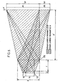
- a projection plane P located in the predetermined three-dimensional zone V is defined.
- This plane shown in FIGS. 3 and 4, is chosen so as to be arranged transversely with respect to a vehicle located in position. V.
- the plane P is the plane (X, Z)
- P1 which is the intersection of the plane P with the upper part V 1 of the volume which contains the windshield of any standard vehicle present in the specified area for which a shot is to be made
- P2 is also considered, which is the intersection of the plane P with the lower part V 2 of the volume containing the license plate of the vehicle. such a standard vehicle.
- the portions P1 and P2 are such that the portion P1 contains the geometric projection of the windshield on the plane P and P2 contains the geometric projection of the license plate on the plane P.
- this plane is the median plane located at equal distance between the plane containing the license plate and the plane passing through the driver's face.
- the projection axis of the projection device makes a large angle with the trajectory of the vehicle, it is advantageous to tilt the plane of the source relative to the projection axis, so as to obtain a projection plane substantially perpendicular to the path.
- the optical projection device 17b and the place where it is available, so that the image of the source 17a is projected on the projection plane P and that in addition the image of the first part source S1 covers the portion P1 and the image of the second source portion S2 covers the portion P2.
- the source 17a comprises the two source parts S1 and S2 shown in FIG. 2
- the diameter of the projection optics will be chosen according to the emission cone of the parts of the source, the available space and the possibilities offered by the technique of producing the chosen projection optics, so as to collect the maximum flow to project it on the plane P.
- the image of the source 17a is formed in the projection plane P. And it is in this plane (neither upstream nor downstream) that the signals originating from the first source part S1 are separated from the signals from the second source portion S2.
- the projection device 17b is thus chosen here as a function of the dimensions of the portions P1 and P2 of the projection plane P, and the dimensions of the source 17a (Note that in another embodiment of the invention, is the source this time which will be chosen according to the portions P1, P2 and characteristics of a predetermined optical projection device).
- the ratio between a signal of maximum intensity received by a receiver entity of the sensor and a minimum intensity signal received by another receiver entity of the sensor is less than a value E, called dynamic displacement factor of the sensor and corresponding to the linear operating range of this sensor (ie avoiding any saturation and avoiding drowning any useful information in noise).
- the source portion S1 transmits mainly in the visible band and the source portion S2 mainly in the infrared band.
- the optical device 17b then projects the image of the source portion S1 on the first portion P1 comprising the driver's face, and the image of the source portion S1 on the second portion P2 comprising the license plate.
- the infrared signals are projected selectively on the portion P2, containing the license plate, and the visible band signals on the portion P1 containing the driver's face or said selected element inside the passenger compartment.
- each source portion S1, S2 is adjusted so as to produce at the level of the shooting means 10 a luminous flux originating from the chosen element and a luminous flux originating from said number plate, such as the difference between said streams is compatible with the dynamic means of shooting.
- the source portion S1 emits a luminous flux of intensity greater by a factor L than the intensity of the luminous flux emitted by the source portion S2, the objective being to obtain a homogeneous image on the sensor.
- L the intensity of the luminous flux emitted by the source portion S2
- the source parts can furthermore transmit signals of different wavelengths or not.
- the optical device 17b it is possible for example to use a Fresnel lens (this makes it possible to obtain a lens of large size, of focal length short and low cost), knowing that the optical quality of the image of the source that one seeks to obtain is not at all critical.
- the rays reflected by the license plate will therefore be limited to those coming from the second source part and the rays reflected by the driver's face through the windshield will therefore be limited to those coming from the first source part.
- a method according to the invention thus makes it possible with a single flash of flash and a single photograph to obtain a usable identification of the vehicle, comprising the representation of the license plate and that of the driver's face, while allowing the using a compact source and selectively projecting the signals of the first or second source portion, depending on the portion considered on the projection plane.
- one will choose an element located behind the windshield, in the passenger compartment and other than the driver's face.
- an optical filter 18 filtering the incident signals according to their spectral band, the filter 18 attenuating the intensity of the signals of the infrared range by a factor K, equal to the ratio of the filter densities between the infrared and visible spectra.
- K is chosen, in an advantageous embodiment of the invention, so that, on average, the ratio between the intensity of the light signals representative of the zone Z1 and the intensity of the light signals representative of the zone Z2 is less than E at the output of the filter 18.
- K will be chosen so as to substantially equalize the intensity of the light signals at the output of the filter 18 and representative of the first portion and the intensity of the light signals at the output of the filter 18 and representative of the second portion of the shot.
- K will be chosen so as to substantially equalize the signals generated by the sensor 10b and representative of the zone Z1 and those generated by the sensor 10b and representative of the zone Z2 of the image.
- a filter 18 such that it has a density close to 0 in the visible range and between 0.5 and 1.5 in the infrared so as to attenuate in a ratio of 5 to 15 the signals coming from the infrared spectral range.
- the waves reflected by a vehicle 16 traveling on the road 3 and present in the detection field of the radar are picked up by the antenna 2 and analyzed in the control unit 4, which calculates the speed of the vehicle 16, and compares this speed calculated with a predefined maximum speed.
- control unit 4 sends a signal to the control box 9 of the device 8, causing the sending from the housing 9 to the flash 17 of an illumination control and sending almost simultaneously from the camera 9 to the camera system 10, a camera control and this at the moment the vehicle is in the shooting position determined previously (this moment is determined by the housing 9 according to the estimated speed for the vehicle).
- a flash is emitted and the shooting system 10 captures an image of the vehicle. This image is stored in memory 12.
- the filter 18 may be replaced by a filter also performing a filtering of the signals as a function of their wavelength, disposed between the camera 10a and the sensor 10b.
- the source 17a is instead unique and emits in the visible and infrared.
- the optical device 17b is then adapted to project the visible part of the source on the first portion P1 of the projection plane P, and to project the portion of the source on the second portion P2 of the projection plane (as indicated above, it is considered that the two images of the source are coplanar, given the low inclination of the image planes introduced by the two optics and the distance between the optical device 17b and the images).
- the optical device 17b may comprise, for example, a focusing module F1 for the signals of the source 17a belonging to the visible spectral band and a focusing module F2 for the signals of the source 17a belonging to the infrared spectral band, the least, a filter attenuating the signals of the visible band being arranged in association with the module F2 (ie upstream or downstream thereof).
- a filter r2 attenuating the signals of the visible band is arranged in association with the focusing module F2.
- a filter r1 attenuating the infra-red signals, is arranged in association with the F1 module.
- the modules F1 and F2 have angularly offset axes so that the optical device 17b splits the image of the source at the level of the scene and illuminates the first portion of the scene in visible light and in the infrared the second portion of the scene .
- these two focusing modules F1 and F2 are two optical Fresnel lens type.
- the image processing module is adapted to apply digital processing to the images stored in the memory 12.
- This treatment makes it possible, for example, to isolate the plate image fraction F corresponding to the number plate on each image I, by referring to a base, also stored in memory 12, of standard plate models.
- a character recognition program can then be applied to the F- plate image fraction.
- This character recognition program provides N number of license estimated from the fraction F image plate, with a confidence score associated P N.
- the module applies, for example, a digital processing on the image I making it possible to isolate the driver's face from the vehicle 16 (in another embodiment, it can isolate the representation of the barrier). breeze from the vehicle and what appears through it, or isolate the seat belt or cell phone held by the driver).
- a digital processing on the image I making it possible to isolate the driver's face from the vehicle 16 (in another embodiment, it can isolate the representation of the barrier). breeze from the vehicle and what appears through it, or isolate the seat belt or cell phone held by the driver).
- the set of numerical data corresponding to the image 1, and / or the estimated registration number N with the associated confidence score P N , and / or to the image fractions F plate and F face , and to the Velocity violations V are then selected and assembled, and then delivered by the control box 9 to the transmission block 13.
- the image I can be sent with only the fractions F plate and F face visible (and other parts of the image I masked) to preserve private information (in particular, the passenger (s) can not be identified).
- the transmission block 13 compresses, formats these data, then sends them, via the communication link 14, to the exploitation center 15.
- the following administrative operations are performed for example: editing and recording of the statement of offense including the data sent by the transmission block 13, calculation of the amount of the fine corresponding to the offense committed by the driver of the vehicle 16, determining the coordinates of the driver from the estimated number of the license plate and sending the statement of offense.
- the number of data transmitted by way of transmission is thus limited and can be further reduced by compression techniques.
- the digital data sent on the transmission channel or channels are very small volume, relevant and of good quality.
- a method and a system according to the invention makes it possible to adapt the means used in order to avoid obtaining an unusable image due to very different reflective characteristics of the various elements that one wants to include in the image. They take advantage of the strong infrared reflection of the plate and the low transmission of new windshields treated to prevent the passage of infrared rays in the passenger compartment and thus its overheating, this for passenger comfort purposes
Landscapes
- Physics & Mathematics (AREA)
- General Physics & Mathematics (AREA)
- Traffic Control Systems (AREA)
- Radar Systems Or Details Thereof (AREA)
- Vehicle Waterproofing, Decoration, And Sanitation Devices (AREA)
Claims (16)
- Verfahren zur Identifikation von Fahrzeugen, die sich auf einer bestimmten Bahn (3) bewegen und einen Fahrer in einer Fahrgastzelle und ein Nummernschild umfassen, wobei das Verfahren Beleuchtungsmittel (17), die eine Vorrichtung (17b) zur Bildprojektion und eine Lichtquelle (17a) mit wenigstens einem ersten und einem zweiten Teil umfassen, und Bildaufnahmemittel (10) einsetzt, die eingangs empfangene Lichtsignale zu verarbeiten vermögen und wenigstens eine optische Vorrichtung (10a) und einen Sensor (10b) umfassen, wobei das Verfahren:in einer Vorbereitungsphase die folgenden Schritte umfasst:- Festlegen einer vorbestimmten Position zur Aufnahme von Fahrzeugen;- in einer in der vorbestimmten Position gelegenen Projektionsebene (P) Bestimmen eines ersten Abschnitts (P1), der dem ausgewählten Teil eines jeden sich in der Aufnahmeposition befindlichen Fahrzeugs entspricht, und eines zweiten Abschnitts (P2), der dem Nummernschild eines jeden sich in der oben genannten vorbestimmten Position befindlichen Fahrzeugs entspricht;- Bilden der Beleuchtungsmittel in der Weise, dass die Bildprojektionsvorrichtung die Abbildung des ersten Lichtquellenteils (17a) auf die Projektionsebene projiziert und dabei den ersten Abschnitt verdeckt, und die Abbildung des zweiten Lichtquellenteils auf die Projektionsebene projiziert und dabei den zweiten Abschnitt verdeckt;- Einstellen der Bildaufnahmemittel in der Weise, dass sowohl das in der Fahrgastzelle des Fahrzeugs befindliche ausgewählte Element als auch das Nummernschild in einer einzigen Aufnahme eines jeden sich in der vorbestimmten Position befindlichen Fahrzeugs beinhaltet ist;und anschließend in einer Ausführungsphase die Schritte umfasst, gemäß denen:- ein sich in der vorbestimmten Position befindliches Fahrzeug erfasst wird;- die Beleuchtungsmittel und die Bildaufnahmemittel nahezu gleichzeitig ausgelöst werden,- eine Aufnahme (Ph) des Fahrzeugs erzielt wird, die eine Wiedergabe des ausgewählten Elements und eine Wiedergabe des Kennzeichens beinhaltet.
- Verfahren nach Anspruch 1,
bei dem sich der erste Lichtquellenteil (S1) räumlich von dem zweiten Lichtquellenteil (S2) unterscheidet. - Verfahren nach Anspruch 1,
dadurch gekennzeichnet, dass die Projektionsvorrichtung (17b) eine erste, die Abbildung des ersten Lichtquellenteils (S1) projizierende Optik (F1) und eine zweite, die Abbildung des zweiten Lichtquellenteils (S2) projizierende Optik (F2) umfasst. - Verfahren nach einem der Ansprüche 1 bis 3,
bei dem der erste Lichtquellenteil (S1) einen Lichtstrahl aussendet, der eine andere Lichtstärke hat als der von dem zweiten Lichtquellenteil (S2) ausgesandte Strahl. - Verfahren nach einem der Ansprüche 1 bis 4,
bei dem die Bildprojektionsvorrichtung (17b) zwischen der Lichtquelle (17a) und der Projektionsebene (P) angeordnet ist. - Verfahren nach einem der Ansprüche 1 bis 4,
bei dem die Signale eines gegebenen Spektralbereichs nur von einem der ersten und zweiten Lichtquellenteile (S1, S2) abgegeben werden. - Verfahren nach Anspruch 6,
bei dem nur der erste Lichtquellenteil (S1) Signale des sichtbaren Spektrums abgibt. - Verfahren nach Anspruch 6 oder 7,
bei dem nur der zweite Lichtquellenteil (S2) Signale des Infrarotspektrums abgibt. - Verfahren nach einem der vorhergehenden Ansprüche,
bei dem in der Vorbereitungsphase die Bildaufnahmemittel derart gebildet werden, dass die Stärke der von den Bildaufnahmemitteln empfangenen Signale in Abhängigkeit von wenigstens der Spektralbereiche abgeschwächt wird. - Verfahren nach Anspruch 9,
bei dem die Abschwächung der Signale derart erfolgt, dass die Stärke der von den Bildaufnahmemitteln empfangenen und für den ersten bzw. den zweiten Bildaufnahmeabschnitt repräsentativen Lichtströme im Wesentlichen ausgeglichen wird. - Verfahren nach einem der Ansprüche 9 bis 10,
bei dem die Bildaufnahme vorher in wenigstens einen ersten Bereich, der das ausgewählte Element eines jeden sich in der Aufnahmeposition befindlichen Fahrzeugs umfasst, und einen zweiten Bereich, der das Nummernschild des Fahrzeugs umfasst, aufgeteilt wurde, und die Abschwächung der Signale zudem in Abhängigkeit des Bereichs erfolgt, für den die Signale repräsentativ sind. - Verfahren nach einem der Ansprüche 9 bis 11,
bei dem das Verhältnis zwischen der Abschwächung der zum Infrarotspektrum gehörenden Signale und der Abschwächung der zum sichtbaren Spektrum gehörenden Signale zwischen 5 und 15 liegt. - Verfahren nach einem der vorhergehenden Ansprüche,
bei dem die Projektionsvorrichtung der Beleuchtungsmittel wenigstens eine Fresnel-Linse umfasst. - Verfahren nach einem der vorhergehenden Ansprüche,
bei dem in der Vorbereitungsphase jeder Lichtquellenteil (S1, S2) derart eingestellt wird, dass bei den Bildaufnahmemitteln (10) ein von dem ausgewählten Element stammender Lichtstrom und ein von dem Nummernschild stammender Lichtstrom erzeugt wird, so dass die Abweichung zwischen den Lichtströmen mit der Dynamik der Bildaufnahmemittel kompatibel ist. - System zur Identifikation von Fahrzeugen, die sich auf einer bestimmten Bahn bewegen und einen Fahrer in einer Fahrgastzelle und ein Nummernschild umfassen, wobei eine Position zur Aufnahme von Fahrzeugen und eine in der vorbestimmten Position gelegenen Projektionsebene (P) vorab festgelegt worden sind und ein erster und ein zweiter Abschnitt (P1; P2), die einem ausgewählten Element bzw. dem Nummernschild eines jeden sich in der Aufnahmeposition befindlichen Fahrzeugs entsprechen, in der Projektionsebene bestimmt worden sind, wobei das System umfasst:- Beleuchtungsmittel (17) mit einer Lichtquelle (17a), die wenigstens einen ersten und einen zweiten Teil umfasst, und einer Vorrichtung (17b) zur Bildprojektion, wobei die Beleuchtungsmittel derart angepasst sind, dass die Bildprojektionsvorrichtung die Abbildung des ersten Teils der Lichtquelle (17a) auf die Projektionsebene projiziert und dabei den ersten Abschnitt verdeckt, und die Abbildung des zweiten Lichtquellenteils auf die Projektionsebene projiziert und dabei den zweiten Abschnitt verdeckt;- Bildaufnahmemittel (10), die eingangs empfangene Lichtsignale zu verarbeiten vermögen und wenigstens eine optische Vorrichtung (10a) und einen Sensor (10b) umfassen, wobei die Bildaufnahmemittel derart angepasst sind, dass sowohl das in der Fahrgastzelle des Fahrzeugs befindliche ausgewählte Elemente als auch das Nummernschild des Fahrzeugs in einer einzigen Aufnahme eines jeden sich in der vorbestimmten Position befindlichen Fahrzeugs enthalten ist;- Mittel zum Erfassen eines in der vorbestimmten Position befindlichen Fahrzeugs;- Mittel zum nahezu gleichzeitigen Auslösen der Beleuchtungsmittel und der Bildaufnahmemittel.
- System zur Identifikation von Fahrzeugen nach Anspruch 15, mit Mitteln, um aus der erfolgten Aufnahme wenigstens einen Aufnahmeteil zu extrahieren.
Applications Claiming Priority (2)
| Application Number | Priority Date | Filing Date | Title |
|---|---|---|---|
| FR0314495 | 2003-12-10 | ||
| FR0314495A FR2863755B1 (fr) | 2003-12-10 | 2003-12-10 | Procede et systeme d'identification d'un vehicule en deplacement |
Publications (2)
| Publication Number | Publication Date |
|---|---|
| EP1542192A1 EP1542192A1 (de) | 2005-06-15 |
| EP1542192B1 true EP1542192B1 (de) | 2006-08-23 |
Family
ID=34508633
Family Applications (1)
| Application Number | Title | Priority Date | Filing Date |
|---|---|---|---|
| EP04292920A Active EP1542192B1 (de) | 2003-12-10 | 2004-12-08 | Verfahren und System zur Identifikation eines sich bewegenden Fahrzeuges |
Country Status (4)
| Country | Link |
|---|---|
| EP (1) | EP1542192B1 (de) |
| AT (1) | ATE337595T1 (de) |
| DE (1) | DE602004002071T2 (de) |
| FR (1) | FR2863755B1 (de) |
Families Citing this family (9)
| Publication number | Priority date | Publication date | Assignee | Title |
|---|---|---|---|---|
| EP2157558B1 (de) | 2008-08-19 | 2015-05-06 | JENOPTIK Robot GmbH | Verfahren und Anordnung zur fotografischen Aufnahme eines zu erfassenden Fahrzeuges |
| WO2011000415A1 (de) * | 2009-06-30 | 2011-01-06 | Siemens Aktiengesellschaft | Verfahren und vorrichtung zur überwachung des strassenverkehrs |
| DE102011000205B4 (de) | 2011-01-18 | 2014-07-17 | Illinois Tool Works Inc. | Vorrichtung und Verfahren zum Reffen eines Schlauchfolienabschnitts |
| DE102011075451B4 (de) | 2011-05-06 | 2014-05-08 | Illinois Tool Works Inc. | Verfahren und Vorrichtung zum Aufreffen eines Schlauchfolienabschnitts auf die Refffinger einer Verpackungsanlage |
| FI124180B (fi) | 2011-09-30 | 2014-04-15 | Illinois Tool Works | Menetelmä käärintäkoneen kuljetustilaan saattamiseksi sekä käärintäkone |
| FI125661B (en) | 2012-09-07 | 2015-12-31 | Signode Int Ip Holdings Llc | Method and apparatus for positioning corner guards on a load |
| FI125411B (en) | 2013-10-31 | 2015-10-15 | Signode Internat Ip Holdings Llc | Method and fasteners for securing the end of a wrapping film web to a packaging machine and packaging machine |
| DE102014106365B4 (de) | 2014-05-07 | 2017-06-14 | Lachenmeier Aps | Verpackungsverfahren zum Verpacken eines Gutes |
| DE102015101489A1 (de) | 2015-02-02 | 2016-08-04 | Signode Industrial Group Llc | Verpackungsvorrichtung und Verfahren zum Betrieb derselben |
Family Cites Families (5)
| Publication number | Priority date | Publication date | Assignee | Title |
|---|---|---|---|---|
| DE2802448C2 (de) * | 1978-01-20 | 1982-03-18 | Dieter 8000 München Schwenk | Verfahren und Vorrichtung zur Herstellung von photographischen Aufnahmen von Fahrzeuginsassen |
| JPS5767916A (en) * | 1980-10-14 | 1982-04-24 | Mitsubishi Electric Corp | Photographing device of car |
| DE3535588A1 (de) * | 1985-10-05 | 1987-04-09 | Robot Foto Electr Kg | Verfahren und vorrichtung zur photographischen erfassung stark leuchtender oder reflektierender teile eines zu photographierenden gesichtsfeldes |
| US6650765B1 (en) * | 2000-01-11 | 2003-11-18 | Pulnix America, Inc. | System for simultaneously imaging vehicles and their license plates |
| DE10223923B4 (de) * | 2002-05-23 | 2004-07-22 | Robot Visual Systems Gmbh | Verfahren und Anordnung zur fotografischen Aufnahme eines Fahrzeuges |
-
2003
- 2003-12-10 FR FR0314495A patent/FR2863755B1/fr not_active Expired - Fee Related
-
2004
- 2004-12-08 DE DE602004002071T patent/DE602004002071T2/de active Active
- 2004-12-08 EP EP04292920A patent/EP1542192B1/de active Active
- 2004-12-08 AT AT04292920T patent/ATE337595T1/de not_active IP Right Cessation
Also Published As
| Publication number | Publication date |
|---|---|
| FR2863755B1 (fr) | 2006-10-27 |
| DE602004002071D1 (de) | 2006-10-05 |
| FR2863755A1 (fr) | 2005-06-17 |
| EP1542192A1 (de) | 2005-06-15 |
| ATE337595T1 (de) | 2006-09-15 |
| DE602004002071T2 (de) | 2007-03-29 |
Similar Documents
| Publication | Publication Date | Title |
|---|---|---|
| EP1923280B1 (de) | Photosensibler Sensor für den Automobilsektor | |
| EP1553429B1 (de) | System und Verfahren für ein Fahrzeug um die Verkehrsbedingungen zu detektieren | |
| FR2886415A1 (fr) | Module de formation d'image | |
| US20090167865A1 (en) | Photographic object recognition correction | |
| EP1542192B1 (de) | Verfahren und System zur Identifikation eines sich bewegenden Fahrzeuges | |
| JP2005117639A (ja) | 環境状況を検出して交通を監視し且つ管制するために道路上に設置される検出デバイス | |
| FR2718871A1 (fr) | Procédé pour la reconnaissance automatique d'un panneau de signalisation routière, et dispositif pour la mise en Óoeuvre de ce procédé. | |
| EP0454516A1 (de) | Hindernisanzeigevorrichtung, insbesondere für selbstfahrende Fahrzeuge | |
| EP1542191B1 (de) | Verfahren und System zur Identifikation eines sich bewegenden Fahrzeuges | |
| KR20140135527A (ko) | 블랙박스 카메라의 렌즈 구조체 | |
| FR2882159A1 (fr) | Systeme de camera pour observer une ou plusieurs zones d'espace | |
| FR2893720A1 (fr) | Dispositif de prise de vues a longue distance | |
| EP3926529B1 (de) | Systeme und methoden zur bestimmung einer anzahl von personen in einem fahrzeug | |
| EP1526492B1 (de) | Verfahren und Vorrichtung zur Identifikation eines sich bewegenden Fahrzeugs | |
| CA2543150A1 (fr) | Procede et dispositif de capture d'une image grand champ et d'une region d'interet de celle-ci | |
| EP3526064A1 (de) | Windschutzscheibe und vorrichtung zur fahrassistenz | |
| FR3041458A1 (fr) | Dispositif d'imagerie, vehicule automobile equipe d'un tel dispositif d'imagerie, et procede associe | |
| EP1713132A2 (de) | Photosensor und Anwendung desselben im Kraftfahrzeug-Bereich | |
| WO1993019376A1 (fr) | Procede et dispositif de mesure optique des dimensions ou de la vitesse d'un objet en mouvement dans un fluide | |
| FR2678412A1 (fr) | Procede pour surveiller, et le cas echeant, photographier automatiquement des objets en mouvement sur une trajectoire predeterminee, et dispositif pour la mise en óoeuvre de ce procede. | |
| WO2019166720A1 (fr) | Détection dynamique de lumière parasite dans une image numérique | |
| EP3394795B1 (de) | Verfahren zur erkennung einer deichsel und zugehöriges computerprogrammprodukt | |
| WO2023041285A1 (fr) | Procede de selection d'un mode de fonctionnement d'un dispositif de capture d'images pour reconnaissance faciale | |
| CH715882A2 (fr) | Instrument acoustique et procédé pour reconnaître un signal acoustique émis par un véhicule. | |
| EP1112653B1 (de) | Kinevideokamera |
Legal Events
| Date | Code | Title | Description |
|---|---|---|---|
| PUAI | Public reference made under article 153(3) epc to a published international application that has entered the european phase |
Free format text: ORIGINAL CODE: 0009012 |
|
| AK | Designated contracting states |
Kind code of ref document: A1 Designated state(s): AT BE BG CH CY CZ DE DK EE ES FI FR GB GR HU IE IS IT LI LT LU MC NL PL PT RO SE SI SK TR |
|
| AX | Request for extension of the european patent |
Extension state: AL BA HR LV MK YU |
|
| 17P | Request for examination filed |
Effective date: 20050610 |
|
| AKX | Designation fees paid |
Designated state(s): AT BE BG CH CY CZ DE DK EE ES FI FR GB GR HU IE IS IT LI LT LU MC NL PL PT RO SE SI SK TR |
|
| GRAP | Despatch of communication of intention to grant a patent |
Free format text: ORIGINAL CODE: EPIDOSNIGR1 |
|
| RAP1 | Party data changed (applicant data changed or rights of an application transferred) |
Owner name: SAGEM DEFENSE SECURITE |
|
| GRAS | Grant fee paid |
Free format text: ORIGINAL CODE: EPIDOSNIGR3 |
|
| GRAA | (expected) grant |
Free format text: ORIGINAL CODE: 0009210 |
|
| AK | Designated contracting states |
Kind code of ref document: B1 Designated state(s): AT BE BG CH CY CZ DE DK EE ES FI FR GB GR HU IE IS IT LI LT LU MC NL PL PT RO SE SI SK TR |
|
| PG25 | Lapsed in a contracting state [announced via postgrant information from national office to epo] |
Ref country code: SK Free format text: LAPSE BECAUSE OF FAILURE TO SUBMIT A TRANSLATION OF THE DESCRIPTION OR TO PAY THE FEE WITHIN THE PRESCRIBED TIME-LIMIT Effective date: 20060823 Ref country code: SI Free format text: LAPSE BECAUSE OF FAILURE TO SUBMIT A TRANSLATION OF THE DESCRIPTION OR TO PAY THE FEE WITHIN THE PRESCRIBED TIME-LIMIT Effective date: 20060823 Ref country code: RO Free format text: LAPSE BECAUSE OF FAILURE TO SUBMIT A TRANSLATION OF THE DESCRIPTION OR TO PAY THE FEE WITHIN THE PRESCRIBED TIME-LIMIT Effective date: 20060823 Ref country code: PL Free format text: LAPSE BECAUSE OF FAILURE TO SUBMIT A TRANSLATION OF THE DESCRIPTION OR TO PAY THE FEE WITHIN THE PRESCRIBED TIME-LIMIT Effective date: 20060823 Ref country code: LT Free format text: LAPSE BECAUSE OF FAILURE TO SUBMIT A TRANSLATION OF THE DESCRIPTION OR TO PAY THE FEE WITHIN THE PRESCRIBED TIME-LIMIT Effective date: 20060823 Ref country code: IT Free format text: LAPSE BECAUSE OF FAILURE TO SUBMIT A TRANSLATION OF THE DESCRIPTION OR TO PAY THE FEE WITHIN THE PRESCRIBED TIME-LIMIT;WARNING: LAPSES OF ITALIAN PATENTS WITH EFFECTIVE DATE BEFORE 2007 MAY HAVE OCCURRED AT ANY TIME BEFORE 2007. THE CORRECT EFFECTIVE DATE MAY BE DIFFERENT FROM THE ONE RECORDED. Effective date: 20060823 Ref country code: IS Free format text: LAPSE BECAUSE OF FAILURE TO SUBMIT A TRANSLATION OF THE DESCRIPTION OR TO PAY THE FEE WITHIN THE PRESCRIBED TIME-LIMIT Effective date: 20060823 Ref country code: IE Free format text: LAPSE BECAUSE OF FAILURE TO SUBMIT A TRANSLATION OF THE DESCRIPTION OR TO PAY THE FEE WITHIN THE PRESCRIBED TIME-LIMIT Effective date: 20060823 Ref country code: FI Free format text: LAPSE BECAUSE OF FAILURE TO SUBMIT A TRANSLATION OF THE DESCRIPTION OR TO PAY THE FEE WITHIN THE PRESCRIBED TIME-LIMIT Effective date: 20060823 Ref country code: AT Free format text: LAPSE BECAUSE OF FAILURE TO SUBMIT A TRANSLATION OF THE DESCRIPTION OR TO PAY THE FEE WITHIN THE PRESCRIBED TIME-LIMIT Effective date: 20060823 |
|
| REG | Reference to a national code |
Ref country code: GB Ref legal event code: FG4D Free format text: NOT ENGLISH |
|
| REG | Reference to a national code |
Ref country code: CH Ref legal event code: EP |
|
| REG | Reference to a national code |
Ref country code: IE Ref legal event code: FG4D Free format text: LANGUAGE OF EP DOCUMENT: FRENCH |
|
| REF | Corresponds to: |
Ref document number: 602004002071 Country of ref document: DE Date of ref document: 20061005 Kind code of ref document: P |
|
| PG25 | Lapsed in a contracting state [announced via postgrant information from national office to epo] |
Ref country code: DK Free format text: LAPSE BECAUSE OF FAILURE TO SUBMIT A TRANSLATION OF THE DESCRIPTION OR TO PAY THE FEE WITHIN THE PRESCRIBED TIME-LIMIT Effective date: 20061123 Ref country code: BG Free format text: LAPSE BECAUSE OF FAILURE TO SUBMIT A TRANSLATION OF THE DESCRIPTION OR TO PAY THE FEE WITHIN THE PRESCRIBED TIME-LIMIT Effective date: 20061123 |
|
| REG | Reference to a national code |
Ref country code: SE Ref legal event code: TRGR |
|
| PG25 | Lapsed in a contracting state [announced via postgrant information from national office to epo] |
Ref country code: ES Free format text: LAPSE BECAUSE OF FAILURE TO SUBMIT A TRANSLATION OF THE DESCRIPTION OR TO PAY THE FEE WITHIN THE PRESCRIBED TIME-LIMIT Effective date: 20061204 |
|
| GBT | Gb: translation of ep patent filed (gb section 77(6)(a)/1977) |
Effective date: 20061127 |
|
| PG25 | Lapsed in a contracting state [announced via postgrant information from national office to epo] |
Ref country code: MC Free format text: LAPSE BECAUSE OF NON-PAYMENT OF DUE FEES Effective date: 20061231 Ref country code: BE Free format text: LAPSE BECAUSE OF NON-PAYMENT OF DUE FEES Effective date: 20061231 |
|
| PG25 | Lapsed in a contracting state [announced via postgrant information from national office to epo] |
Ref country code: PT Free format text: LAPSE BECAUSE OF FAILURE TO SUBMIT A TRANSLATION OF THE DESCRIPTION OR TO PAY THE FEE WITHIN THE PRESCRIBED TIME-LIMIT Effective date: 20070125 |
|
| REG | Reference to a national code |
Ref country code: IE Ref legal event code: FD4D |
|
| PLBE | No opposition filed within time limit |
Free format text: ORIGINAL CODE: 0009261 |
|
| STAA | Information on the status of an ep patent application or granted ep patent |
Free format text: STATUS: NO OPPOSITION FILED WITHIN TIME LIMIT |
|
| 26N | No opposition filed |
Effective date: 20070524 |
|
| BERE | Be: lapsed |
Owner name: SAGEM DEFENSE SECURITE Effective date: 20061231 |
|
| PG25 | Lapsed in a contracting state [announced via postgrant information from national office to epo] |
Ref country code: GR Free format text: LAPSE BECAUSE OF FAILURE TO SUBMIT A TRANSLATION OF THE DESCRIPTION OR TO PAY THE FEE WITHIN THE PRESCRIBED TIME-LIMIT Effective date: 20061124 |
|
| PG25 | Lapsed in a contracting state [announced via postgrant information from national office to epo] |
Ref country code: EE Free format text: LAPSE BECAUSE OF FAILURE TO SUBMIT A TRANSLATION OF THE DESCRIPTION OR TO PAY THE FEE WITHIN THE PRESCRIBED TIME-LIMIT Effective date: 20060823 |
|
| REG | Reference to a national code |
Ref country code: FR Ref legal event code: TP |
|
| PG25 | Lapsed in a contracting state [announced via postgrant information from national office to epo] |
Ref country code: TR Free format text: LAPSE BECAUSE OF FAILURE TO SUBMIT A TRANSLATION OF THE DESCRIPTION OR TO PAY THE FEE WITHIN THE PRESCRIBED TIME-LIMIT Effective date: 20060823 Ref country code: LU Free format text: LAPSE BECAUSE OF NON-PAYMENT OF DUE FEES Effective date: 20061208 Ref country code: HU Free format text: LAPSE BECAUSE OF FAILURE TO SUBMIT A TRANSLATION OF THE DESCRIPTION OR TO PAY THE FEE WITHIN THE PRESCRIBED TIME-LIMIT Effective date: 20070224 |
|
| PG25 | Lapsed in a contracting state [announced via postgrant information from national office to epo] |
Ref country code: CY Free format text: LAPSE BECAUSE OF FAILURE TO SUBMIT A TRANSLATION OF THE DESCRIPTION OR TO PAY THE FEE WITHIN THE PRESCRIBED TIME-LIMIT Effective date: 20060823 |
|
| REG | Reference to a national code |
Ref country code: GB Ref legal event code: 732E |
|
| REG | Reference to a national code |
Ref country code: CH Ref legal event code: PL |
|
| PG25 | Lapsed in a contracting state [announced via postgrant information from national office to epo] |
Ref country code: LI Free format text: LAPSE BECAUSE OF NON-PAYMENT OF DUE FEES Effective date: 20081231 Ref country code: CH Free format text: LAPSE BECAUSE OF NON-PAYMENT OF DUE FEES Effective date: 20081231 |
|
| NLS | Nl: assignments of ep-patents |
Owner name: SAGEM SECURITE Effective date: 20081127 |
|
| REG | Reference to a national code |
Ref country code: NL Ref legal event code: TD Effective date: 20100916 |
|
| REG | Reference to a national code |
Ref country code: FR Ref legal event code: CD |
|
| REG | Reference to a national code |
Ref country code: DE Ref legal event code: R082 Ref document number: 602004002071 Country of ref document: DE Representative=s name: BOSCH JEHLE PATENTANWALTSGESELLSCHAFT MBH, DE Effective date: 20120308 Ref country code: DE Ref legal event code: R081 Ref document number: 602004002071 Country of ref document: DE Owner name: MORPHO, FR Free format text: FORMER OWNER: SAGEM SECURITE, PARIS, FR Effective date: 20120308 |
|
| REG | Reference to a national code |
Ref country code: FR Ref legal event code: CA Effective date: 20130917 |
|
| REG | Reference to a national code |
Ref country code: FR Ref legal event code: PLFP Year of fee payment: 12 |
|
| REG | Reference to a national code |
Ref country code: FR Ref legal event code: PLFP Year of fee payment: 13 |
|
| REG | Reference to a national code |
Ref country code: FR Ref legal event code: PLFP Year of fee payment: 14 |
|
| REG | Reference to a national code |
Ref country code: FR Ref legal event code: CD Owner name: SAFRAN IDENTITY & SECURITY, FR Effective date: 20180123 |
|
| PGFP | Annual fee paid to national office [announced via postgrant information from national office to epo] |
Ref country code: SE Payment date: 20191125 Year of fee payment: 16 Ref country code: DE Payment date: 20191119 Year of fee payment: 16 Ref country code: CZ Payment date: 20191126 Year of fee payment: 16 Ref country code: NL Payment date: 20191125 Year of fee payment: 16 |
|
| PGFP | Annual fee paid to national office [announced via postgrant information from national office to epo] |
Ref country code: FR Payment date: 20191120 Year of fee payment: 16 |
|
| PGFP | Annual fee paid to national office [announced via postgrant information from national office to epo] |
Ref country code: GB Payment date: 20191122 Year of fee payment: 16 |
|
| REG | Reference to a national code |
Ref country code: DE Ref legal event code: R119 Ref document number: 602004002071 Country of ref document: DE |
|
| PG25 | Lapsed in a contracting state [announced via postgrant information from national office to epo] |
Ref country code: CZ Free format text: LAPSE BECAUSE OF NON-PAYMENT OF DUE FEES Effective date: 20201208 |
|
| REG | Reference to a national code |
Ref country code: SE Ref legal event code: EUG |
|
| REG | Reference to a national code |
Ref country code: NL Ref legal event code: MM Effective date: 20210101 |
|
| GBPC | Gb: european patent ceased through non-payment of renewal fee |
Effective date: 20201208 |
|
| PG25 | Lapsed in a contracting state [announced via postgrant information from national office to epo] |
Ref country code: NL Free format text: LAPSE BECAUSE OF NON-PAYMENT OF DUE FEES Effective date: 20210101 |
|
| PG25 | Lapsed in a contracting state [announced via postgrant information from national office to epo] |
Ref country code: FR Free format text: LAPSE BECAUSE OF NON-PAYMENT OF DUE FEES Effective date: 20201231 |
|
| PG25 | Lapsed in a contracting state [announced via postgrant information from national office to epo] |
Ref country code: SE Free format text: LAPSE BECAUSE OF NON-PAYMENT OF DUE FEES Effective date: 20201209 Ref country code: DE Free format text: LAPSE BECAUSE OF NON-PAYMENT OF DUE FEES Effective date: 20210701 Ref country code: GB Free format text: LAPSE BECAUSE OF NON-PAYMENT OF DUE FEES Effective date: 20201208 |