EP1542151B1 - Verfahren und Anordnung zur elektronischen Aufnahme abgerollter Fingerabdrücke - Google Patents
Verfahren und Anordnung zur elektronischen Aufnahme abgerollter Fingerabdrücke Download PDFInfo
- Publication number
- EP1542151B1 EP1542151B1 EP04029189A EP04029189A EP1542151B1 EP 1542151 B1 EP1542151 B1 EP 1542151B1 EP 04029189 A EP04029189 A EP 04029189A EP 04029189 A EP04029189 A EP 04029189A EP 1542151 B1 EP1542151 B1 EP 1542151B1
- Authority
- EP
- European Patent Office
- Prior art keywords
- image
- enclosing
- images
- finger
- recording
- Prior art date
- Legal status (The legal status is an assumption and is not a legal conclusion. Google has not performed a legal analysis and makes no representation as to the accuracy of the status listed.)
- Expired - Lifetime
Links
Images


Classifications
-
- G—PHYSICS
- G06—COMPUTING OR CALCULATING; COUNTING
- G06V—IMAGE OR VIDEO RECOGNITION OR UNDERSTANDING
- G06V40/00—Recognition of biometric, human-related or animal-related patterns in image or video data
- G06V40/10—Human or animal bodies, e.g. vehicle occupants or pedestrians; Body parts, e.g. hands
- G06V40/12—Fingerprints or palmprints
- G06V40/1335—Combining adjacent partial images (e.g. slices) to create a composite input or reference pattern; Tracking a sweeping finger movement
Definitions
- the invention relates to a method and an arrangement for the electronic recording of a moving object, in particular for receiving a finger which has been unrolled on a support surface.
- the invention finds primarily application for the production of electronic fingerprints, but can also be used to advantage in object tracking for the intelligent control of a variable in position and / or size sampling window.
- the background for the use of fingerprints in forensics is the uniqueness of the dermal scar images, which are not inheritable and which are immutable from the fourth embryonic month to dissolution after death.
- the image template can be the finger itself, a fingerprint applied to paper by ink or a trace photogram. The latter two techniques were and are mainly used by the police. With the help of pattern recognition techniques capable of extracting the characteristics of a fingerprint, it is possible to automate the identification and verification of fingerprints.
- the above-mentioned techniques have increasingly been integrated into electronic systems that allow the finger to be picked up directly. This shortens the recording and evaluation time, which at the same time improves the quality of the images. If a finger has not been detected correctly, it is possible to immediately repeat the process of recording that one finger.
- the electronic image capture of fingerprints is usually done with matrix or line sensors based on CCD or CMOS technology.
- the fingerprint is converted as an image template by special optics and sensors in an electronic image and then digitized, creating a raster image with a fixed spatial and gray scale resolution.
- capacitive, thermal, ultrasound-based or pressure-sensitive sensors can also be used to record electronic fingerprints.
- the causes for the loss of information are due not only to the deformation of the finger and the resulting changes at two different points in time, especially in too little temporal scanning of the finger by the image acquisition unit. That is, to ensure that a finger is picked up correctly, the image acquisition unit must have a minimum frame rate, depending on the method of assembly used, so that disturbing processes, such as twisting or slipping during the rolling process of the finger, can be detected.
- the frames coming from the imaging unit have a fixed size and are based on a fixed time regime (dictated by a clock generator or an event trigger).
- the unwinding speed (and possibly its change) as well as the size of the finger contact surface (and its real change in the unrolling process) can not be taken into account in the readout regime of the image pickup unit.
- two neighboring fingerprint strips must have a sufficiently large intersection for the respective method. This can only be achieved if a fast time sampling occurs when rolling the finger. This is currently being realized by sensors with a high image read rate (frame rate) of more than 25 frames / second (B / s).
- the invention is therefore based on the object to find a new way to electronically record unrolled fingerprints, the high-resolution frames and a tight sequence of images for seamless composition of the individual images to an overall picture without resorting to expensive image sensors with high frame rate (read speed) got to.
- the object is achieved in a method for the electronic recording of a moving object, in particular for recording a finger unrolled on a recording surface, wherein the object is detected with its structures during movement by means of a spatially resolving image recording unit in a sequence of individual images and processed as a two-dimensional electronic image , is achieved by determining from the position and size of the object in at least one of the individual images read out of the image recording unit a figure enclosing the object, that from the enclosing figure rectangle magnified by tolerance additions aligned parallel to the row and column direction of the sensor, and that the enlarged rectangle is used to predict and adjust the size and location of an active pixel area of the image acquisition unit for at least one subsequently read image, such that the read active pixel range of the image pickup unit due to its adaptation always kept small and a higher frame rate in the sensor reading or data transmission is realized.
- the enclosing figure of the object image of the currently scanned image is determined by a respective gradient image formed in the column and in the row direction, a difference of adjacent gray values in the row or in the column direction being formed for the generation of the gradient image for each pixel.
- the pixels of each gradient image are preferably formed from the difference between the gray values of the preceding and succeeding pixel of the currently examined pixel of the rows or columns.
- start and end values of the enclosing figure of the object image are advantageously determined from at least one gradient image of the rows or columns aligned in the direction of the object movement, a first and a last significant difference of adjacent gray values per row or column Calculation of the start and end values of the figure enclosing the object is determined.
- the significant differences are expediently determined by exceeding threshold values. It proves advantageous to calculate an average value or a median value of the start and end values determined from the gradient image in at least one dimension which corresponds to the main movement direction of the object, the mean or median values then being linear boundaries of the object image being rectangular form enclosing figure.
- the start and end values are entered into a location histogram at least from the gradient image that corresponds to the main movement direction of the object, the locations at which the integral frequency distribution reaches a significant threshold form the boundaries of a figure enclosing the object image in a rectangular manner ,
- This threshold value can make sense 5% of the integral frequency distribution.
- it is also possible to choose the maximum value of the frequency distribution To save on computational and storage capacity, it is advantageous to use only the start and end values of selected rows or columns of the gradient image for determining the boundaries of the rectangular enclosing figure.
- a tolerance addition for generating the enlarged rectangle is determined differently depending on a detected movement sequence of the object, wherein from the at least two previously read images after determining the boundaries of the respective enclosing figure different evaluation algorithms based on the temporal Changing the boundaries of the enclosing figure can be applied in the successive pictures.
- roll-over trace routine is at the heart of the image capture of a rolled-up finger to provide a complete, high-resolution series of individual images for the composition of the complete footprint of a rolled-up finger
- roll-off tracking is conveniently accomplished by a roll-off detection that is in place Number of progressions in the same direction shifts the boundaries of the enclosing figure, the motion tracking switches to the roll tracking, initiated and terminated by a AbrollParkung, which terminates the Abrollv adoptedung at a reversal of direction of movement of the boundaries of the surrounding figure.
- an intermediate storage of all images used for the start detection is advantageously carried out within the Abrollstarterkennung to keep the already read images for the subsequent complete composition of the unrolled finger available.
- the object of the invention in an arrangement for electronically recording a moving object, in particular for recording a finger unrolled on a recording surface, with an image recording unit for recording a sequence of two-dimensional individual images of a moving object, wherein the composition of an overall image of the moving object Individual images have local overlaps, according to the invention solved in that the image pickup unit a logic unit for the current calculation of a a limited pixel area, which encloses the object image closely, on the basis of at least one image previously read by the image acquisition unit, in that the logic unit is assigned a program memory, a data memory, a processor and an interface, the processor being provided for controlling the data flows, and in that the interface for data transfer of the images, which are controlled in a defined manner by the logic unit with respect to size and position of their pixel area, is present on an external computer unit, wherein the computer unit contains the image processing for assembling the temporally successively recorded images into an overall image.
- the image acquisition unit preferably has an optoelectronic sensor, but may also be equipped with a capacitive, inductive, thermal, ultrasonic or other type of contact sensor.
- Suitable optoelectronic image sensors are CCD arrays or CMOS arrays (each in the form of a matrix or line array).
- the image acquisition unit can also contain a sensor with a low frame rate ( ⁇ 25 B / s), in which the low frame rate is based only on the reading of all pixels of the sensor, but the reading of images from an arbitrarily programmable active pixel area with a much larger frame rate is feasible.
- the image acquisition unit preferably has a large-area sensor in which a complete footprint or handprint with high resolution but low frame rate can be realized by a single sensor reading, in which a defined partial area of the receiving surface is defined for receiving individual unrolled fingers is, wherein the sensor in a correspondingly limited active pixel area, which is assigned to the defined portion of the receiving area for the unrolling finger, for reading pixelreduced images is controllable, so that the frame rate for recording unrolled fingerprints compared to foot or hand prints significantly increased becomes.
- the image acquisition unit may also be a high-frame-rate sensor ( ⁇ 25 B / s) in which the interface is the limiting element of data transmission, so that only a small portion of the image data can be transmitted in "real time" ,
- the readout of data-reduced images according to the invention takes place from arbitrarily accessible pixel areas of the data memory in order subsequently to increase the data rate of the transmission via the interface.
- the method according to the invention for determining the boundaries of the active pixel area advantageously takes place in a logic unit (hardware) which precedes (the arithmetic unit for assembling the images of the object) and which is expediently an FPGA (freely programmable gate array).
- the logic unit can also be a PLD (programmable logic element) or an ASIC (application-specific integrated circuit).
- the processor used to control the processes and data streams of the logic unit may advantageously be a microprocessor (MPU), a digital signal processor (DSP) or a microcontroller (MCU).
- the processor can also be integrated directly into the logic unit, the program memory or the external computer unit.
- the invention is based on the basic idea of a gray scale image of variable surface area and / or structure that can be represented as function G (x, y), in which x and y are the coordinates of a respective pixel of the image and G records its gray values electronically.
- a moving object having such an image characteristic is picked up at different times t n sequentially with t n + 1 > t n having different views as a function G n to form the overall image G from images G n (x, y), from the image pickup unit only portions of interest of the object surface are recorded whose size varies depending on the rotational speed of the object.
- the essence of the method according to the invention consists in defining or predicting from each currently read-out image, in each case for the next image, an adapted limited pixel detail which, with the necessary certainty, completely contains the fingerprint to be detected and is set as the read-out window of the image acquisition unit, by the read-out rate (Frame rate) the Increase image acquisition unit.
- the read-out rate Fre rate
- WOI Window of Interest
- the invention it is possible to realize an electronic recording of unrolled fingerprints, which generates the high resolution images adapted to the object size and movement in close succession and allows their reliable composition of the images to the overall image without the need for expensive image sensors or interfaces with high Frame rate must be used.
- the invention allows to choose the frame rate much higher than is possible with the currently used high-resolution sensors or image processing interfaces with complete reading of the image area.
- due to the electronic adjustment of the sensor readout window applications such as taking a complete hand and rolling a finger with one and the same device are possible.
- Fig. 1 is the basic principle of the method for electronically recording an imprint image (hereinafter: fingerprint 11) from the surface of a finger 1 shown.
- the method is based on having a finger 1 sequentially at different times in different, overlapping views is added to subsequently - which is not the subject of the invention - to put together an overall picture of the unrolled finger 1.
- the finger surface Due to the above-mentioned "roll-off rule" for the finger 1, the finger surface can be picked up by the image pickup unit 2 only piecemeal as a successive series of frames.
- the size and position of the recorded images 31 in this case vary depending on the current impression surface and the unwinding speed of the finger 1.
- a complex control method is proposed to function of the current footprint and the unwinding of the finger 1 a suitably restricted section in the reading of the Imaging unit 2 set and monitor, so that high frame rates can be achieved without having to resort to expensive image sensors.
- an image pickup unit 2 which can be read out, for example, at 25 B / s, takes 75 pictures during a rolling process of 3 s duration. Each of these 75 images is a full image containing the fingerprint 11 at a defined time in a particular location (size and position).
- This information loss increases as the unwinding speed of the finger 1 increases relative to the frame rate of the image pickup unit 2.
- the image acquisition unit 2 has to fulfill a minimum image rate for assembly so that, for example, processes such as twisting or slipping during the rolling process can be detected and corrected.
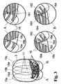
- FIG Fig. 2 in the left partial view the result of an overall picture 3 of a rolled-out finger 1 is stylized, as it occurs when rolling the finger 1 with ink on paper and how it is to be generated as an overall image 3 by composing a sequence of individual images.
- the overall image 3 is to be assembled according to the detail images of a finger 1 of three images per time interval shown in the upper right row, wherein according to the prior art, a series of three snapshots of the finger 1 are scanned as a frame of the entire image acquisition unit 2 in a fixed time regime , Thereafter, information-bearing image parts are extracted, whereby the three image strips 12a to 12c are formed. If the time interval between the snapshots is too long (ie, the frame rate of the image pickup unit 2 is too low) compared to the movement of the finger 1, then, when the overall image 3 is assembled, even if the overlapping of the edge areas of the image strips 12a to 12c occurs, overlapping problems arise if the overlay Finger 1 was additionally laterally shifted or rotated within the rolling motion.
- the two upper papillary lines 13 and 14 have performed a translational movement and the uppermost papillary line 13 has additionally experienced a rotational movement.
- the first segment 131 of the upper papillary line 13 from the strip 12a is closer to the third segment 143 of the next papillary line 14 than the associated second segment 132 of the upper papillary line 13 from the strip 12b. This can lead to the incorrect assembly of at least the papillary lines 13 and 14 in the overall image 3 and thus to misinterpretations of the structures of the unrolled finger 1.
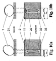
- the image pickup unit 2 consists of a diffuse illumination unit 24, a prism 25 and a camera 26 with an imaging optics and an optoelectronic sensor 22.
- the base surface of the prism 25 is the actual recording surface 21.
- the light is transmitted through the illumination unit 24 is coupled into the prism 25 in such a way that it is totally reflected on the base surface without an applied finger 1, ie if the limit angle for total reflection (here glass / air) is exceeded.
- a brightly illuminated image is generated by means of the imaging optics on the sensor 22 in the camera 26.
- a finger 1 is placed on the prism 25, changes at the points where the finger 1 rests, the transition glass / air to glass / skin. Since the skin has a higher refractive index than air, the critical angle of total reflection is greater. The total reflection is thus canceled at these points and the light is decoupled.
- the sensor 22 which is arranged in the camera 26, the finger 1 is therefore imaged as an image in black and white transitions. The sensor 22 converts these light intensities into electrical signals which are subsequently digitized, as a result of which a raster image with a defined spatial and grayscale resolution is produced.
- the optoelectronic image recording of fingerprints 11 takes place - without limiting the generality - with matrix or line sensors based on CCD or CMOS technology.
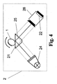
- Fig. 4 For simplicity's sake, and not limited to the image pickup principle described above, only the pickup surface 21 and the image pickup unit 2 will be referred to, the unrolled finger being referred to hereinafter as the base of the prism 25 1 in the image pickup unit 2 in any manner in an electronic image converted and output digitized. It is also possible to take fingerprints 11 instead of an opto-electronic sensor 22 to equivalently use capacitive, pressure-sensitive, ultrasound-based or thermal sensors within a suitably designed image pickup unit.
- the inventive method preferably in hardware in an arrangement according to Fig. 5 is realized, takes into account different object surfaces and speeds and thus ensures an optimally adapted scanning of the moving object.
- Starting point of the procedure - as in Fig. 1 displayed - is an (arbitrary) information that tells you that a rolling process should take place.
- This information is usually transmitted by an external computer unit 4, which processes the recorded data.
- the information can also be specified by another external system, with the arrangement according to Fig. 5 communicatively communicates via the interface. Through this sent Information knows the arrangement that a finger 1 will soon be launched and initiates corresponding detection steps. With this active circuit, the following detection steps of the method can take place.
- the task of the PR routine 61 is to check in each image 31 supplied by the image acquisition unit 2 whether a valid fingerprint 11 is present on the support surface 21 or not.
- an x-gradient image 71 and a y-gradient image 72 are generated from each image 31 by forming differences of adjacent gray-scale pixels in each line or column.
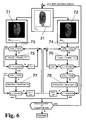
- Figure 6 a possible program sequence for recognizing a "valid fingerprint" is shown, this program sequence in each case referring to a single image 31 within an image sequence.
- a gradient image 71 in the x-direction with the values Dx i, j and a gradient image 72 in the y-direction with Dy i, j are formed, in each line or each column differences 73 and 74 are formed from the recorded adjacent gray value pixels. It is possible for each pixel of the gradient image 71 to be generated currently within the rows to form the difference 73 from the direct predecessor pixel and the direct successor pixel of the associated gray value pixel in the image 31 or - to improve the sensitivity - from the predecessor and the successor successor pixels. The same applies to the differences 74 in the column direction.
- the gray value threshold SwA defines a difference value size beyond which a difference value 73 or 74 formed from predecessor and successor gray value pixels counts as "valid". This gray value threshold SwA does not have to be firmly defined, but can also be variable (changing from image to image) and thus better adapt to the image quality of the image 31 received. If the difference is "valid", a variable CountR j defined in the difference counter 75 for the lines of the x-gradient image 71 or one in the difference counter 76, respectively for the columns of the ⁇ gradient image 72 variable defined variable CountC i counted one higher.
- the threshold SwC can be selected to be greater than the threshold SwB. In the present example, both thresholds SwC and SwB were chosen to be the same size as to be more sensitive to the placement of a finger 1.
- the MT routine 62 which is described in U.S. Pat Fig. 7 is shown schematically, is used to track the due to a rolling movement of the finger 1 successively changed position of the current fingerprint 11 (footprint).
- the starting point for the evaluation by the MT routine 62 may also be predetermined by a switch in the control panel, a foot switch or an external device (eg, arithmetic unit 4).
- the image 31 read out of the image pickup unit 2 has the size of the entire active area of the sensor 22 and is thus one frame. In the subsequent runs, depending on the calculated area size, only a selected active pixel area 23 of the sensor 22 is read out, so that the read-out image 31, relative to the entire sensor area, represents a partial image.
- the MT routine 62 whose function is based on the Fig. 7 and the schematic representations of Fig. 8 is to be explained, the tracking of the moving finger 1 is used to prepare his defined unwinding after it has been recognized as a "valid finger". In this case, the position and size of an information-relevant section of the image 31 is recalculated for each subsequently adapted image 31 to be read out of the image acquisition unit 2 and set as the pixel sector 23 of the sensor 22 to be read out. In the MT routine 62 - as in Fig.
- a gradient image 81 in the x direction with gray values Dx i, j and a gradient image 82 in the y direction with Dy i, j or the gradient images 71 are calculated from each image 31 which has a gray value distribution G i, j and 72 taken directly from the PR routine 61.
- the difference values are - as in the PR routine 61 - formed from a pixel environment (eg difference from predecessor predecessor and successor of the successor of the pixel to be determined).
- the method selected by the above-mentioned method is expediently applied to only a part of the columns or lines of each image 31 for the purpose of reducing the computation effort so as to keep the computation time low.
- the start and end values determined therefrom form the boundaries of a preferably rectangular enclosing figure 32 which completely contains the fingerprint 11. But there are also ellipses or similar planar figures as enclosing figure 32 makes sense.
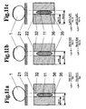
- the enclosing figure 32, as in rectangular shape in 10a and 10b can also be based on the definition of a left start limit 35 (StartX) and a right end limit 36 (EndX), as in Fig. 11a to 11c be limited indicated if the calculation of the enclosing figure 32 for reasons of almost complete utilization of the receiving surface 21 laterally to the rolling direction of the finger 1 not worthwhile.
- the found values are entered into the register of the sensor 22 of the image acquisition unit 2, which then only records and reproduces this range when the next image 31 is read out.
- the RSR routine 63 compares the positions of FIG. 32 with those of the previous image images 32.
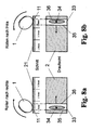
- Fig. 8a and Fig. 8b is each stylized a rolling process to the right and to the left.
- the receiving surface 21 is sensibly divided into three thirds in order to position the finger 1 correctly so that the fingerprint 11 is completely unrolled onto the receiving surface 21.
- the finger 1 is preferably placed in the second third and rolled into the first or third third. In this case, a rolling movement is already performed, whereby the center of gravity 34 and the boundaries 35 and 36 (StartX and EndX) of the rectangle 33 change.
- the finger 1 is placed in the middle of the support surface 21 on the second third and rolled to the left to a starting point for the complete rolling process.
- the center of gravity, the (left) start boundary 35 and (right) end boundary 36 of the rectangle 33 are also moved to the left.
- the rolling process can be started by the finger 1 is rolled to the right.
- the changed direction of movement of the (right-hand) end boundary 36 is preferably detected and the occurrence of this event is communicated to all system components which require this information.
- the detection of the starting point can also be determined by shifting the center of gravity or as a combination of the reversal of movement from the end boundary 36 and the center of gravity 34.
- the indicators serve to change both the direction of displacement of the center of gravity 34 and the direction of displacement of the end boundary 36 (EndX Line) of the rectangle 33.
- This variant is more robust than the first two.
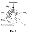
- a kind of ring buffer memory 41 is required to process the read-out images 31 (see FIG Fig. 9 ), in which all images 31, which are stored from the actual starting point of the rolling process up to the image 31, from which the starting point is determined, are buffered.
- at least a number p of images 31 must fit into the ring buffer memory 41 as needed to determine the beginning of the unrolling process. If the starting point is established, first all the images 31 are read out of the ring buffer memory 41 and forwarded for processing. In the event that you want to unroll to the left, everything behaves the same, except that not the right, but the start boundary 35 (left border of the rectangle 33) is used for viewing.
- Arithmetic unit 4 eg a PC
- the arithmetic unit 4 is also informed of how many images 31 were used for the determination of the unwinding process, so that it is buffered from a buffer memory in which the images 31 already used for the adjustment of the active pixel area 23 of the image acquisition unit 2 are stored of the overall picture 3 used.
- a ring buffer memory 41 according to Fig. 9 in which the images 31 required for the RSR routine 63 are buffered.
- the number of memory locations in the buffer 41 must be one greater than the number of frames 31 used to determine the roll-off. If a starting point of a rolling process has been detected, loop 2 in Fig. 1 finished and passed into the loop 3. This starts again with a support test (see PR routine 61) to end the recording of the rolling process in the unexpected start of the finger 1. If a valid fingerprint 11 is still present, it will switch to roll-over tracking.
- the RT routine 64 is used to track the finger 1 during the defined unwinding. It not only determines the center of gravity 34 and the boundaries 35 and 36 of the fingerprint 11, such as the motion track 62, but also determines the speed of the roll-off operation by adjusting the speed of the center of gravity 34 and / or the speed of the respective boundaries 35 and 36 of the rectangle 33 separately be calculated. In addition, the acceleration of the finger center of gravity 34 and / or the respective rectangle boundaries 35 and 36 is determined to detect short-term changes in the unwinding speed.
- the tolerance between the enclosing figure 32 of the fingerprint 11 and the boundaries 35 and 36 of the enlarged rectangle 33 can be made smaller, in contrast to the MT algorithm 62 ,
- the tolerance range must be chosen to be relatively large and thus image readout time is wasted. This is not problematic in the MT routine 62 since the captured fingerprint 11 is used only for visualization. In a rolling process, however, it is necessary to read out as many images 31 per second as possible, since any increase in the readout speed will improve the proper composition of the overall image 3. Therefore, with a priori knowledge about the started rolling process, the readout time can be significantly reduced.
- the Abrollstarterkennung 63 in which direction is rolled, ie the tolerance range must have only in one direction the maximum value.
- the speed and possibly occurring accelerations can be calculated, thereby making a more accurate prediction of the boundaries of the figure 32 enclosing the fingerprint 11 and thus of the required rectangle 33.
- the procedure for determining the speed is in Fig. 11a to 11c shown.
- the speed of the center of gravity in the x-direction eg centroid of the imprint, center of gravity calculated as the difference of the boundaries 35 and 36 of the enclosing figure 32 in the x-direction
- the velocities of the two boundaries in X direction For the velocities in y-directions, this applies analogously if rolling in the y-direction is implemented.
- the index n describes an arbitrary instant of the taking of an image 31 in the value range of 0 ⁇ n ⁇ N-1, with N as the total number of all captured images 31.
- n-1 is the time of the predecessor and n + 1 of the successor.
- ⁇ t represents the cycle time, ie the time it takes to read out the active pixel region 23 and thus a limited image 31.
- f PixelClock is the pixel clock between 12 to 27 MHz of the sensor 22. With this pixel clock, the individual pixels are read out.
- N Rows and N Column are the number of rows and columns needed in the active pixel area 23 of the sensor 22.
- R opcycle is a fixed integer value of 140. This is the time required to complete all intermediate steps before and after reading one row of the sensor 22 is needed.
- R Itime has a fixed integer value of 34, otherwise R Itime is zero. This results, for example, in the case of a pixel frequency of 25 MHz and a complete readout of the sensor 22 with 1280 ⁇ 1024 pixels, a frame rate of 16.8 images per second.
- the width of the image 31 is reduced to half (640 x 1024 pixels), for example, and a frame rate of 30 B / s (frames per second) is achieved.
- Another physical quantity for calculating the prediction of the next boundary 35 or 36 of the rectangle 33 is the acceleration. It takes into account any speed change in the calculation.
- the acceleration is determined from the two preceding speeds, whereby the first prediction is to be performed without an acceleration calculation.
- a routine is presented below which realizes a more accurate prediction of the boundaries 35 and 36 of the rectangle 33.
- the basic requirement is that after the already presented RT routine 64, the exact limits 35 and 36 of the Fingerprint 11 and the surrounding him figure 32 were determined and that are made as initial conditions two assumptions. Since at least two images 31 are needed to determine the velocity, an assumption must be made, since otherwise no prediction can be made for determining the position of the boundaries of the second image 31. Therefore, when a rolling operation by the RSR routine 63 has been judged to be started, it is assumed that the position of the start boundary 35 for the first image 31 is equal to the position of the start boundary 35 for the second image 31.
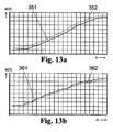
- Fig. 13 the results of the method are shown, where s (n) is the movement of the position of the start limit 35 and e (n) is the movement of the position of the end limit 36.
- the representations of the Fig. 13a and 13b represent a rolling movement from an origin at pixel 0 to the maximum value of the respective image capturing unit 2.
- Fig. 13a is the movement of the position of the start boundary 35, where the solid line represents the predicted position 351 of the start boundary 35 of the rectangle 33 and the broken line represents the actual reached position 352 of the imaged fingerprint 11.
- the position 352 actually reached must not be below the solid line of the calculated position 351, since otherwise the fingerprint 11 will be judged.
- x '(n + 1) is either the position to be calculated of the start limit s' (n + 1) or the end limit e' (n + 1).
- the apostrophe means that it is a predictable quantity that is not used to calculate the value after the second.
- the quantity a x (n) represents the acceleration and v x (n) the speed of the starting value (a s , v s ) or of the final value (a E , v E ) at the current time.
- the current position is represented by x (n).
- Tol1 is the tolerance of the start value when scrolling from left to right. It may be smaller than the tolerance Tol2 of the final value, since the position 352 of the start limit 35 at time n is definitely smaller than the position 352 of the start limit 35 at time n + 1. Thus, as the predicted position 351 of the start limit 35 at time n + 1, theoretically, the actual position 352 of the start limit 35 may be taken at time n and Tol1 may take the value 0. However, since the detection of the roll-off occurs within the roll-off sequence and the direction change is a feature for the roll-off end, a certain size must be used for the tolerance Tol1.
- Tol1 may again be smaller than Tol2, since the rolling process is carried out from right to left and the final boundary 36 at time n is definitely greater than the position 362 of the end boundary 36 at time n + 1.
- the position of the subsequent rectangle 33 results from these values, and the fixed rectangle size must be placed around the calculated enclosing figure 32 such that the distances of the boundaries of the rectangle 33 from the minimum start value and the maximum end value of the enclosing figure 32 are equal on all sides ,
- the resulting position of the solid rectangle 33 is programmed in the image acquisition unit 2 as an active pixel region 23 for the subsequent image 31.
- the positioning of the rectangle 33 which is always the same size, can also - as described above - be carried out with the aid of a center of gravity algorithm which, for example, searches for the centroid of the fingerprint 11 and places the solid rectangle 33 around it. This has the consequence that a circumcision of the fingerprint 11 can not be excluded.
- the excising of an enlarged rectangle 33 containing the fingerprint 11 can also take place outside the image acquisition unit 2, if the data rate when reading the complete sensor 22 is sufficient, but the limiting element for the required data rate is the transmission channel.
- the method according to the invention can be applied in the same way, except that the frame as picture 31 is present as the basis for calculation and not already a selected active pixel area 23. It is then no longer necessary to make a prediction where the next start or stop is Final limit 35 or 36 is because you have the image 31 as a frame of the image pickup unit 2 available, so you can do without the calculation of speeds and accelerations. That is, by a high frame rate image pickup unit 2, the frame in the processing unit 5 (in accordance with FIG Fig.
- the start limit 35 is maintained as an input value without recalculation of speed or acceleration, but increases the tolerance.
- RT routine 64 is as in FIG Fig. 1 seen, surrounded by the support detection 61 and a Abroll gleicherkennung 65 (RER routine). PR routine 61 and RER routine 65 check whether the finger 1 has been lifted during the rolling process or the finger 1 has been moved over a series of images 31 in the opposite direction to the detected rolling direction. If the finger 1 was lifted during the unwinding, this is detected by the PR routine 61 and interpreted as a rolling shut-off. The other way of terminating the RT routine 64 is effected by a roll-off detection 65, which will be explained below.
- an RER routine 65 it is determined whether or not a coasting operation has been completed. In this case, the positions determined by the RT routine 64 of the start and end limits 35 and 36 of the rectangle 33 are used. At a Rolling operation, the user should, if he wants to end the rolling process, be prompted to roll the finger 1 against the original rolling direction. As a result, the limits 35 and 36 determined by the RT algorithm (for example via more than three images 31) change counter to the original scrolling direction. This can then be interpreted unambiguously as rolling closure. In order to make the RER routine 65 robust, it is expedient to use 5 images to make sure that the unwinding process has ended.
- the roll-off is evaluated as the lifting of the finger 1, which is detected by the PR routine 61 described above. If the roll-off has been detected, the registers in which the adapted rectangle 33 was stored as the active pixel region 23 of the sensor 22 are deleted in the image acquisition unit 2, so that again the entire sensor surface is switched active.
- Fig. 5 a structure is shown, which subsequently to the image pickup unit 2, a logic unit 51, a processor 54, a program memory 52, a data memory 53 and an interface 55, wherein the logic unit 51 and the processor 54 may be combined as a data processing or processing unit. Also, the program and data memory 67 and 68 can be to a memory be summarized. As processor 54, the CPU of the external computing unit 4 could also be used.
- the image pickup unit 2 whose sensor is based on CMOS or CCD technology preferably includes a drive circuit and an analog-to-digital converter.
- CMOS or CCD technology preferably includes a drive circuit and an analog-to-digital converter.
- fingerprint 11 as a two-dimensional digital image 31 at the output of the image acquisition unit 2. This is written to the data memory 53 via the logic unit 51.
- the processing unit 5 the above-described algorithms and processing routines are executed.
- the logic unit 51 can be implemented by a FPGA (Field Programmable Gate Array), PLD (Programmable Logic Device), ASIC (Application Specific Integrated Circuit).
- a microcontroller MCU
- MPU microprocessor
- DSP digital signal processor
- the processor 54 can also be completely dispensed with if the logic unit 51 is able to perform all functions, including communication with the interface 55 itself. Conversely, the logic unit 51 can be dispensed with if the processor 54 is able to realize all the tasks of the logic unit 51.
- the image data bus 57 would then have to be led by the processor 54 to the interface 55 and a direct coupling of the processor 54 to the data memory 53 would exist.
- the interface 55 represents the interface to the outside and can be arbitrary (eg USB2.0, IEEE1394, Ethernet).
- the processing routines 61 to 65 can also be partially or completely also outside, for example with the in Fig. 5 represented external computing unit 4, executed and the setting of the active pixel area 23 in the register of the image pickup unit 2 are controlled via the interface 55 (and possibly the logic unit 51).
Landscapes
- Engineering & Computer Science (AREA)
- Human Computer Interaction (AREA)
- Physics & Mathematics (AREA)
- General Physics & Mathematics (AREA)
- Multimedia (AREA)
- Theoretical Computer Science (AREA)
- Image Input (AREA)
- Measurement Of The Respiration, Hearing Ability, Form, And Blood Characteristics Of Living Organisms (AREA)
- Collating Specific Patterns (AREA)
- Length Measuring Devices By Optical Means (AREA)
- Studio Devices (AREA)
Applications Claiming Priority (2)
| Application Number | Priority Date | Filing Date | Title |
|---|---|---|---|
| DE10358738 | 2003-12-11 | ||
| DE10358738A DE10358738B3 (de) | 2003-12-11 | 2003-12-11 | Verfahren und Anordnung zur elektronischen Aufnahme abgerollter Fingerabdrücke |
Publications (3)
| Publication Number | Publication Date |
|---|---|
| EP1542151A2 EP1542151A2 (de) | 2005-06-15 |
| EP1542151A3 EP1542151A3 (de) | 2008-01-23 |
| EP1542151B1 true EP1542151B1 (de) | 2009-09-30 |
Family
ID=34485388
Family Applications (1)
| Application Number | Title | Priority Date | Filing Date |
|---|---|---|---|
| EP04029189A Expired - Lifetime EP1542151B1 (de) | 2003-12-11 | 2004-12-09 | Verfahren und Anordnung zur elektronischen Aufnahme abgerollter Fingerabdrücke |
Country Status (6)
| Country | Link |
|---|---|
| US (1) | US7613334B2 (OSRAM) |
| EP (1) | EP1542151B1 (OSRAM) |
| JP (1) | JP4280706B2 (OSRAM) |
| AT (1) | ATE444537T1 (OSRAM) |
| CA (1) | CA2488492A1 (OSRAM) |
| DE (2) | DE10358738B3 (OSRAM) |
Families Citing this family (18)
| Publication number | Priority date | Publication date | Assignee | Title |
|---|---|---|---|---|
| JP4671027B2 (ja) * | 2005-05-02 | 2011-04-13 | ソニー株式会社 | 認証装置、認証方法及びプログラム |
| JP4547629B2 (ja) * | 2006-02-10 | 2010-09-22 | ソニー株式会社 | 登録装置、登録方法及び登録プログラム |
| US8547114B2 (en) | 2006-11-14 | 2013-10-01 | Cypress Semiconductor Corporation | Capacitance to code converter with sigma-delta modulator |
| JP4611427B2 (ja) * | 2007-01-24 | 2011-01-12 | 富士通株式会社 | 画像読取装置、画像読取プログラム、画像読取方法 |
| WO2009006557A1 (en) * | 2007-07-03 | 2009-01-08 | Cypress Semiconductor Corporation | Method for improving scan time and sensitivity in touch sensitive user interface device |
| US8482536B1 (en) | 2008-07-23 | 2013-07-09 | Cypress Semiconductor Corporation | Compensation of signal values for a touch sensor |
| US8432252B2 (en) * | 2009-06-19 | 2013-04-30 | Authentec, Inc. | Finger sensor having remote web based notifications |
| US9069405B2 (en) | 2009-07-28 | 2015-06-30 | Cypress Semiconductor Corporation | Dynamic mode switching for fast touch response |
| US8723825B2 (en) | 2009-07-28 | 2014-05-13 | Cypress Semiconductor Corporation | Predictive touch surface scanning |
| US8723827B2 (en) | 2009-07-28 | 2014-05-13 | Cypress Semiconductor Corporation | Predictive touch surface scanning |
| IT1402987B1 (it) * | 2010-06-22 | 2013-09-27 | Green Bit S P A | "procedimento e dispositivo per la rilevazione di oggetti in movimento, ad esempio per la rilevazione di impronte digitali" |
| US9268991B2 (en) * | 2012-03-27 | 2016-02-23 | Synaptics Incorporated | Method of and system for enrolling and matching biometric data |
| USD776664S1 (en) * | 2015-05-20 | 2017-01-17 | Chaya Coleena Hendrick | Smart card |
| KR20170102668A (ko) | 2016-03-02 | 2017-09-12 | 삼성전자주식회사 | 지문 감지 센서, 이를 포함하는 전자 장치 및 지문 감지 센서의 동작 방법 |
| CN106096359B (zh) * | 2016-05-30 | 2017-10-31 | 广东欧珀移动通信有限公司 | 一种解锁控制方法及移动终端 |
| DE102016114188A1 (de) | 2016-08-01 | 2018-02-01 | JENETRIC GmbH | Vorrichtung und Verfahren zur Direktaufnahme von Abdrücken abgerollter Finger |
| US10102415B1 (en) * | 2018-03-29 | 2018-10-16 | Secugen Corporation | Method and apparatus for simultaneous multiple fingerprint enrollment |
| CN112135065B (zh) * | 2020-11-19 | 2021-04-27 | 深圳市汇顶科技股份有限公司 | 指纹检测的方法、指纹检测装置和电子设备 |
Family Cites Families (18)
| Publication number | Priority date | Publication date | Assignee | Title |
|---|---|---|---|---|
| DK155242C (da) * | 1985-05-02 | 1989-07-31 | Jydsk Telefon As | Fremgangsmaade og apparat til automatisk aftastning af fingeraftryk |
| US4933976A (en) * | 1988-01-25 | 1990-06-12 | C.F.A. Technologies, Inc. | System for generating rolled fingerprint images |
| US5230025A (en) * | 1990-08-31 | 1993-07-20 | Digital Biometrics, Inc. | Method and apparatus for capturing skin print images |
| US5812252A (en) * | 1995-01-31 | 1998-09-22 | Arete Associates | Fingerprint--Acquisition apparatus for access control; personal weapon and other systems controlled thereby |
| US5748766A (en) * | 1996-04-30 | 1998-05-05 | Identix Incorporated | Method and device for reducing smear in a rolled fingerprint image |
| FR2749955B1 (fr) * | 1996-06-14 | 1998-09-11 | Thomson Csf | Systeme de lecture d'empreintes digitales |
| US6075876A (en) * | 1997-05-07 | 2000-06-13 | Draganoff; Georgi Hristoff | Sliding yardsticks fingerprint enrollment and verification system and method |
| US6178255B1 (en) | 1998-04-28 | 2001-01-23 | Cross Match Technologies, Inc. | Individualized fingerprint scanner |
| DE19851544C1 (de) * | 1998-11-09 | 2000-05-31 | Heimann Biometric Systems Gmbh | Erzeugen eines abgerollten Fingerabdruckbildes aus einer Serie von Einzelbildern |
| EP1054340B1 (en) * | 1999-05-17 | 2008-05-28 | Nippon Telegraph and Telephone Corporation | Surface shape recognition apparatus and method |
| US6483932B1 (en) * | 1999-08-19 | 2002-11-19 | Cross Match Technologies, Inc. | Method and apparatus for rolled fingerprint capture |
| US6628377B1 (en) * | 2000-04-04 | 2003-09-30 | Stmicroelectronics, Inc. | Scanning optical semiconductor fingerprint detector |
| JP2001319338A (ja) * | 2000-05-11 | 2001-11-16 | Samsung Electronics Co Ltd | 光ディスクの記録装置および記録方法 |
| SE0001761L (sv) * | 2000-05-15 | 2001-07-02 | Ericsson Telefon Ab L M | Metod för alstring av en sammansatt bild samt en apparat för detektering av fingeravtryck |
| DE10024559B4 (de) * | 2000-05-18 | 2004-03-11 | Optigraf Ag Vaduz | Verfahren zur Erkennung von Objekten |
| JP4169185B2 (ja) * | 2002-02-25 | 2008-10-22 | 富士通株式会社 | 画像連結方法、プログラム及び装置 |
| JP2007524441A (ja) * | 2003-04-04 | 2007-08-30 | ルミディム インコーポレイテッド | マルチスペクトルバイオメトリックセンサ |
| US20050047631A1 (en) * | 2003-08-26 | 2005-03-03 | Cross Match Technologies, Inc. | Method and apparatus for rolled fingerprint image capture with variable blending |
-
2003
- 2003-12-11 DE DE10358738A patent/DE10358738B3/de not_active Expired - Fee Related
-
2004
- 2004-11-25 CA CA002488492A patent/CA2488492A1/en not_active Abandoned
- 2004-12-07 US US11/008,819 patent/US7613334B2/en active Active
- 2004-12-09 AT AT04029189T patent/ATE444537T1/de not_active IP Right Cessation
- 2004-12-09 DE DE502004010154T patent/DE502004010154D1/de not_active Expired - Lifetime
- 2004-12-09 EP EP04029189A patent/EP1542151B1/de not_active Expired - Lifetime
- 2004-12-10 JP JP2004358162A patent/JP4280706B2/ja not_active Expired - Fee Related
Also Published As
| Publication number | Publication date |
|---|---|
| DE502004010154D1 (de) | 2009-11-12 |
| JP4280706B2 (ja) | 2009-06-17 |
| ATE444537T1 (de) | 2009-10-15 |
| DE10358738B3 (de) | 2005-06-02 |
| CA2488492A1 (en) | 2005-06-11 |
| JP2005182786A (ja) | 2005-07-07 |
| US20050129292A1 (en) | 2005-06-16 |
| EP1542151A2 (de) | 2005-06-15 |
| EP1542151A3 (de) | 2008-01-23 |
| US7613334B2 (en) | 2009-11-03 |
Similar Documents
| Publication | Publication Date | Title |
|---|---|---|
| EP1542151B1 (de) | Verfahren und Anordnung zur elektronischen Aufnahme abgerollter Fingerabdrücke | |
| DE69622476T2 (de) | Verfahren und Gerät zur Objekterkennung innerhalb des Gesichtfeldes eines Abbildungsgerätes | |
| DE68928999T2 (de) | Kamera mit breitem dynamischem bereich | |
| DE69707886T2 (de) | Verfahren und gerät zum lokalisieren einer sich bewegenden zone und bestimmung der schnellheit und richtung der bewegung eines gebietes von relativer bewegung in einer szene | |
| DE69032326T2 (de) | Dynamisches verfahren um gegenstände zu erkennen und bildverarbeitungsgerät dafür | |
| EP1583022A2 (de) | Verfahren und Anordnung zur Aufnahme interessierender Bereiche von beweglichen Objekten | |
| DE102008048325B4 (de) | Betätigungseingabegerät | |
| DE69523670T2 (de) | Anzeigeverfahren und -gerät | |
| DE102009015142B4 (de) | Fahrzeugumgebungs-Erkennungs-Vorrichtung und Steuerungssystem zum Verfolgen eines vorausfahrenden Fahrzeugs | |
| DE69111377T2 (de) | Kamera mit gegenstandshervorhebung und bewegungsdetektion. | |
| EP1432231A2 (de) | Einrichtung und Verfahren zur störungsarmen Aufnahme von hochaufgelösten zweidimensionalen Bildern | |
| EP3136711A1 (de) | Verfahren zur erzeugung und auswertung eines bilds | |
| DE112008002646T5 (de) | Fahrzeuginterne Bildverarbeitungsvorrichtung, Bildverarbeitungsverfahren und Programm | |
| EP2028605A1 (de) | Detektionsverfahren für symmetrische Muster | |
| DE69203785T2 (de) | Entfernungsmesseinrichtung mittels zweidimensionaler Bilder. | |
| DE69128634T2 (de) | Bildlesesystem | |
| DE69507463T2 (de) | Vorrichtung und verfahren zur verkehrsüberwachung | |
| DE102018201909A1 (de) | Verfahren und Vorrichtung zur Objekterkennung | |
| EP3663976A1 (de) | Verfahren zur erfassung von fingerabdrücken | |
| DE102022002637B3 (de) | Kamerasystem und Verfahren zu dessen Betrieb | |
| EP3663981A1 (de) | Verfahren zur erfassung von fingerabdrücken | |
| DE112017007162T5 (de) | Gesichtsermittlungsvorrichtung, dazugehöriges Steuerungsverfahren und Programm | |
| DE10142457B4 (de) | Digitale Bildmessung retroreflektierender Marken | |
| DE112018006812T5 (de) | Fahrzeugbildsynthesevorrichtung | |
| DE102010002312A1 (de) | Verfahren und Vorrichtung zur Analyse eines Bildes einer Bilderfassungseinrichtung für ein Fahrzeug |
Legal Events
| Date | Code | Title | Description |
|---|---|---|---|
| PUAI | Public reference made under article 153(3) epc to a published international application that has entered the european phase |
Free format text: ORIGINAL CODE: 0009012 |
|
| AK | Designated contracting states |
Kind code of ref document: A2 Designated state(s): AT BE BG CH CY CZ DE DK EE ES FI FR GB GR HU IE IS IT LI LT LU MC NL PL PT RO SE SI SK TR |
|
| AX | Request for extension of the european patent |
Extension state: AL BA HR LV MK YU |
|
| RAP1 | Party data changed (applicant data changed or rights of an application transferred) |
Owner name: CROSS MATCH TECHNOLOGIES GMBH |
|
| PUAL | Search report despatched |
Free format text: ORIGINAL CODE: 0009013 |
|
| AK | Designated contracting states |
Kind code of ref document: A3 Designated state(s): AT BE BG CH CY CZ DE DK EE ES FI FR GB GR HU IE IS IT LI LT LU MC NL PL PT RO SE SI SK TR |
|
| AX | Request for extension of the european patent |
Extension state: AL BA HR LV MK YU |
|
| 17P | Request for examination filed |
Effective date: 20080229 |
|
| AKX | Designation fees paid |
Designated state(s): AT BE BG CH CY CZ DE DK EE ES FI FR GB GR HU IE IS IT LI LT LU MC NL PL PT RO SE SI SK TR |
|
| GRAP | Despatch of communication of intention to grant a patent |
Free format text: ORIGINAL CODE: EPIDOSNIGR1 |
|
| GRAS | Grant fee paid |
Free format text: ORIGINAL CODE: EPIDOSNIGR3 |
|
| GRAA | (expected) grant |
Free format text: ORIGINAL CODE: 0009210 |
|
| AK | Designated contracting states |
Kind code of ref document: B1 Designated state(s): AT BE BG CH CY CZ DE DK EE ES FI FR GB GR HU IE IS IT LI LT LU MC NL PL PT RO SE SI SK TR |
|
| REG | Reference to a national code |
Ref country code: GB Ref legal event code: FG4D Free format text: NOT ENGLISH Ref country code: CH Ref legal event code: EP |
|
| REG | Reference to a national code |
Ref country code: IE Ref legal event code: FG4D |
|
| REF | Corresponds to: |
Ref document number: 502004010154 Country of ref document: DE Date of ref document: 20091112 Kind code of ref document: P |
|
| PG25 | Lapsed in a contracting state [announced via postgrant information from national office to epo] |
Ref country code: SE Free format text: LAPSE BECAUSE OF FAILURE TO SUBMIT A TRANSLATION OF THE DESCRIPTION OR TO PAY THE FEE WITHIN THE PRESCRIBED TIME-LIMIT Effective date: 20090930 Ref country code: LT Free format text: LAPSE BECAUSE OF FAILURE TO SUBMIT A TRANSLATION OF THE DESCRIPTION OR TO PAY THE FEE WITHIN THE PRESCRIBED TIME-LIMIT Effective date: 20090930 Ref country code: FI Free format text: LAPSE BECAUSE OF FAILURE TO SUBMIT A TRANSLATION OF THE DESCRIPTION OR TO PAY THE FEE WITHIN THE PRESCRIBED TIME-LIMIT Effective date: 20090930 |
|
| LTIE | Lt: invalidation of european patent or patent extension |
Effective date: 20090930 |
|
| PG25 | Lapsed in a contracting state [announced via postgrant information from national office to epo] |
Ref country code: SI Free format text: LAPSE BECAUSE OF FAILURE TO SUBMIT A TRANSLATION OF THE DESCRIPTION OR TO PAY THE FEE WITHIN THE PRESCRIBED TIME-LIMIT Effective date: 20090930 Ref country code: PL Free format text: LAPSE BECAUSE OF FAILURE TO SUBMIT A TRANSLATION OF THE DESCRIPTION OR TO PAY THE FEE WITHIN THE PRESCRIBED TIME-LIMIT Effective date: 20090930 |
|
| NLV1 | Nl: lapsed or annulled due to failure to fulfill the requirements of art. 29p and 29m of the patents act | ||
| PG25 | Lapsed in a contracting state [announced via postgrant information from national office to epo] |
Ref country code: RO Free format text: LAPSE BECAUSE OF FAILURE TO SUBMIT A TRANSLATION OF THE DESCRIPTION OR TO PAY THE FEE WITHIN THE PRESCRIBED TIME-LIMIT Effective date: 20090930 Ref country code: CZ Free format text: LAPSE BECAUSE OF FAILURE TO SUBMIT A TRANSLATION OF THE DESCRIPTION OR TO PAY THE FEE WITHIN THE PRESCRIBED TIME-LIMIT Effective date: 20090930 Ref country code: IS Free format text: LAPSE BECAUSE OF FAILURE TO SUBMIT A TRANSLATION OF THE DESCRIPTION OR TO PAY THE FEE WITHIN THE PRESCRIBED TIME-LIMIT Effective date: 20100130 Ref country code: ES Free format text: LAPSE BECAUSE OF FAILURE TO SUBMIT A TRANSLATION OF THE DESCRIPTION OR TO PAY THE FEE WITHIN THE PRESCRIBED TIME-LIMIT Effective date: 20100110 Ref country code: EE Free format text: LAPSE BECAUSE OF FAILURE TO SUBMIT A TRANSLATION OF THE DESCRIPTION OR TO PAY THE FEE WITHIN THE PRESCRIBED TIME-LIMIT Effective date: 20090930 Ref country code: PT Free format text: LAPSE BECAUSE OF FAILURE TO SUBMIT A TRANSLATION OF THE DESCRIPTION OR TO PAY THE FEE WITHIN THE PRESCRIBED TIME-LIMIT Effective date: 20100201 |
|
| REG | Reference to a national code |
Ref country code: IE Ref legal event code: FD4D |
|
| PG25 | Lapsed in a contracting state [announced via postgrant information from national office to epo] |
Ref country code: CY Free format text: LAPSE BECAUSE OF FAILURE TO SUBMIT A TRANSLATION OF THE DESCRIPTION OR TO PAY THE FEE WITHIN THE PRESCRIBED TIME-LIMIT Effective date: 20090930 Ref country code: SK Free format text: LAPSE BECAUSE OF FAILURE TO SUBMIT A TRANSLATION OF THE DESCRIPTION OR TO PAY THE FEE WITHIN THE PRESCRIBED TIME-LIMIT Effective date: 20090930 |
|
| BERE | Be: lapsed |
Owner name: CROSS MATCH TECHNOLOGIES G.M.B.H. Effective date: 20091231 |
|
| PG25 | Lapsed in a contracting state [announced via postgrant information from national office to epo] |
Ref country code: DK Free format text: LAPSE BECAUSE OF FAILURE TO SUBMIT A TRANSLATION OF THE DESCRIPTION OR TO PAY THE FEE WITHIN THE PRESCRIBED TIME-LIMIT Effective date: 20090930 Ref country code: NL Free format text: LAPSE BECAUSE OF FAILURE TO SUBMIT A TRANSLATION OF THE DESCRIPTION OR TO PAY THE FEE WITHIN THE PRESCRIBED TIME-LIMIT Effective date: 20090930 Ref country code: IE Free format text: LAPSE BECAUSE OF FAILURE TO SUBMIT A TRANSLATION OF THE DESCRIPTION OR TO PAY THE FEE WITHIN THE PRESCRIBED TIME-LIMIT Effective date: 20090930 Ref country code: MC Free format text: LAPSE BECAUSE OF NON-PAYMENT OF DUE FEES Effective date: 20100701 |
|
| REG | Reference to a national code |
Ref country code: CH Ref legal event code: PL |
|
| PLBE | No opposition filed within time limit |
Free format text: ORIGINAL CODE: 0009261 |
|
| STAA | Information on the status of an ep patent application or granted ep patent |
Free format text: STATUS: NO OPPOSITION FILED WITHIN TIME LIMIT |
|
| 26N | No opposition filed |
Effective date: 20100701 |
|
| PG25 | Lapsed in a contracting state [announced via postgrant information from national office to epo] |
Ref country code: LI Free format text: LAPSE BECAUSE OF NON-PAYMENT OF DUE FEES Effective date: 20091231 Ref country code: CH Free format text: LAPSE BECAUSE OF NON-PAYMENT OF DUE FEES Effective date: 20091231 Ref country code: BE Free format text: LAPSE BECAUSE OF NON-PAYMENT OF DUE FEES Effective date: 20091231 Ref country code: GR Free format text: LAPSE BECAUSE OF FAILURE TO SUBMIT A TRANSLATION OF THE DESCRIPTION OR TO PAY THE FEE WITHIN THE PRESCRIBED TIME-LIMIT Effective date: 20091231 |
|
| PG25 | Lapsed in a contracting state [announced via postgrant information from national office to epo] |
Ref country code: BG Free format text: LAPSE BECAUSE OF FAILURE TO SUBMIT A TRANSLATION OF THE DESCRIPTION OR TO PAY THE FEE WITHIN THE PRESCRIBED TIME-LIMIT Effective date: 20091231 |
|
| PG25 | Lapsed in a contracting state [announced via postgrant information from national office to epo] |
Ref country code: LU Free format text: LAPSE BECAUSE OF NON-PAYMENT OF DUE FEES Effective date: 20091209 |
|
| PG25 | Lapsed in a contracting state [announced via postgrant information from national office to epo] |
Ref country code: AT Free format text: LAPSE BECAUSE OF NON-PAYMENT OF DUE FEES Effective date: 20091209 |
|
| PG25 | Lapsed in a contracting state [announced via postgrant information from national office to epo] |
Ref country code: HU Free format text: LAPSE BECAUSE OF FAILURE TO SUBMIT A TRANSLATION OF THE DESCRIPTION OR TO PAY THE FEE WITHIN THE PRESCRIBED TIME-LIMIT Effective date: 20100401 |
|
| PG25 | Lapsed in a contracting state [announced via postgrant information from national office to epo] |
Ref country code: TR Free format text: LAPSE BECAUSE OF FAILURE TO SUBMIT A TRANSLATION OF THE DESCRIPTION OR TO PAY THE FEE WITHIN THE PRESCRIBED TIME-LIMIT Effective date: 20090930 |
|
| REG | Reference to a national code |
Ref country code: FR Ref legal event code: PLFP Year of fee payment: 12 |
|
| REG | Reference to a national code |
Ref country code: FR Ref legal event code: PLFP Year of fee payment: 13 |
|
| REG | Reference to a national code |
Ref country code: FR Ref legal event code: PLFP Year of fee payment: 14 |
|
| REG | Reference to a national code |
Ref country code: DE Ref legal event code: R082 Ref document number: 502004010154 Country of ref document: DE Representative=s name: GLEIM PETRI PATENT- UND RECHTSANWALTSPARTNERSC, DE Ref country code: DE Ref legal event code: R082 Ref document number: 502004010154 Country of ref document: DE Representative=s name: GLEIM PETRI OEHMKE PATENT- UND RECHTSANWALTSPA, DE |
|
| REG | Reference to a national code |
Ref country code: DE Ref legal event code: R079 Ref document number: 502004010154 Country of ref document: DE Free format text: PREVIOUS MAIN CLASS: G06K0009000000 Ipc: G06V0010000000 |
|
| REG | Reference to a national code |
Ref country code: DE Ref legal event code: R082 Ref document number: 502004010154 Country of ref document: DE Representative=s name: GLEIM PETRI PATENT- UND RECHTSANWALTSPARTNERSC, DE |
|
| PGFP | Annual fee paid to national office [announced via postgrant information from national office to epo] |
Ref country code: GB Payment date: 20231109 Year of fee payment: 20 |
|
| PGFP | Annual fee paid to national office [announced via postgrant information from national office to epo] |
Ref country code: IT Payment date: 20231110 Year of fee payment: 20 Ref country code: FR Payment date: 20231122 Year of fee payment: 20 Ref country code: DE Payment date: 20231107 Year of fee payment: 20 |
|
| REG | Reference to a national code |
Ref country code: DE Ref legal event code: R071 Ref document number: 502004010154 Country of ref document: DE |
|
| REG | Reference to a national code |
Ref country code: GB Ref legal event code: PE20 Expiry date: 20241208 |
|
| PG25 | Lapsed in a contracting state [announced via postgrant information from national office to epo] |
Ref country code: GB Free format text: LAPSE BECAUSE OF EXPIRATION OF PROTECTION Effective date: 20241208 |
|
| PG25 | Lapsed in a contracting state [announced via postgrant information from national office to epo] |
Ref country code: GB Free format text: LAPSE BECAUSE OF EXPIRATION OF PROTECTION Effective date: 20241208 |