EP1541997A1 - Verfahren und System zur Messung der Impedanz eines Ammoniaksensors auf Zeolithbasis - Google Patents
Verfahren und System zur Messung der Impedanz eines Ammoniaksensors auf Zeolithbasis Download PDFInfo
- Publication number
- EP1541997A1 EP1541997A1 EP04078339A EP04078339A EP1541997A1 EP 1541997 A1 EP1541997 A1 EP 1541997A1 EP 04078339 A EP04078339 A EP 04078339A EP 04078339 A EP04078339 A EP 04078339A EP 1541997 A1 EP1541997 A1 EP 1541997A1
- Authority
- EP
- European Patent Office
- Prior art keywords
- sensor
- icell
- vcell
- current
- impedance
- Prior art date
- Legal status (The legal status is an assumption and is not a legal conclusion. Google has not performed a legal analysis and makes no representation as to the accuracy of the status listed.)
- Withdrawn
Links
- 238000000034 method Methods 0.000 title claims abstract description 33
- QGZKDVFQNNGYKY-UHFFFAOYSA-N Ammonia Chemical compound N QGZKDVFQNNGYKY-UHFFFAOYSA-N 0.000 title claims description 46
- 229910021529 ammonia Inorganic materials 0.000 title claims description 19
- 229910021536 Zeolite Inorganic materials 0.000 title claims description 12
- HNPSIPDUKPIQMN-UHFFFAOYSA-N dioxosilane;oxo(oxoalumanyloxy)alumane Chemical compound O=[Si]=O.O=[Al]O[Al]=O HNPSIPDUKPIQMN-UHFFFAOYSA-N 0.000 title claims description 12
- 239000010457 zeolite Substances 0.000 title claims description 12
- 238000002847 impedance measurement Methods 0.000 title 1
- 238000013508 migration Methods 0.000 claims abstract description 12
- 230000005012 migration Effects 0.000 claims abstract description 12
- 239000007789 gas Substances 0.000 description 26
- MWUXSHHQAYIFBG-UHFFFAOYSA-N Nitric oxide Chemical compound O=[N] MWUXSHHQAYIFBG-UHFFFAOYSA-N 0.000 description 24
- 150000002500 ions Chemical class 0.000 description 8
- 238000012360 testing method Methods 0.000 description 8
- MCMNRKCIXSYSNV-UHFFFAOYSA-N Zirconium dioxide Chemical compound O=[Zr]=O MCMNRKCIXSYSNV-UHFFFAOYSA-N 0.000 description 4
- 239000003990 capacitor Substances 0.000 description 4
- 229910000069 nitrogen hydride Inorganic materials 0.000 description 4
- 239000000523 sample Substances 0.000 description 3
- XSQUKJJJFZCRTK-UHFFFAOYSA-N Urea Chemical compound NC(N)=O XSQUKJJJFZCRTK-UHFFFAOYSA-N 0.000 description 2
- 238000013459 approach Methods 0.000 description 2
- 239000004202 carbamide Substances 0.000 description 2
- 238000010531 catalytic reduction reaction Methods 0.000 description 2
- 230000002596 correlated effect Effects 0.000 description 2
- 238000010586 diagram Methods 0.000 description 2
- 239000003054 catalyst Substances 0.000 description 1
- 230000008859 change Effects 0.000 description 1
- 229910052729 chemical element Inorganic materials 0.000 description 1
- 238000006243 chemical reaction Methods 0.000 description 1
- 150000001875 compounds Chemical class 0.000 description 1
- 230000001419 dependent effect Effects 0.000 description 1
- 230000009977 dual effect Effects 0.000 description 1
- 230000005284 excitation Effects 0.000 description 1
- 239000000446 fuel Substances 0.000 description 1
- 238000002347 injection Methods 0.000 description 1
- 239000007924 injection Substances 0.000 description 1
- 238000005259 measurement Methods 0.000 description 1
- 238000012986 modification Methods 0.000 description 1
- 230000004048 modification Effects 0.000 description 1
- 238000012544 monitoring process Methods 0.000 description 1
- 238000011084 recovery Methods 0.000 description 1
- 230000009467 reduction Effects 0.000 description 1
- 238000006722 reduction reaction Methods 0.000 description 1
- 239000000243 solution Substances 0.000 description 1
- 230000001052 transient effect Effects 0.000 description 1
Images



Classifications
-
- G—PHYSICS
- G01—MEASURING; TESTING
- G01N—INVESTIGATING OR ANALYSING MATERIALS BY DETERMINING THEIR CHEMICAL OR PHYSICAL PROPERTIES
- G01N33/00—Investigating or analysing materials by specific methods not covered by groups G01N1/00 - G01N31/00
- G01N33/0004—Gaseous mixtures, e.g. polluted air
- G01N33/0009—General constructional details of gas analysers, e.g. portable test equipment
- G01N33/0027—General constructional details of gas analysers, e.g. portable test equipment concerning the detector
- G01N33/0036—General constructional details of gas analysers, e.g. portable test equipment concerning the detector specially adapted to detect a particular component
- G01N33/0054—Ammonia
-
- G—PHYSICS
- G01—MEASURING; TESTING
- G01N—INVESTIGATING OR ANALYSING MATERIALS BY DETERMINING THEIR CHEMICAL OR PHYSICAL PROPERTIES
- G01N27/00—Investigating or analysing materials by the use of electric, electrochemical, or magnetic means
- G01N27/02—Investigating or analysing materials by the use of electric, electrochemical, or magnetic means by investigating impedance
- G01N27/04—Investigating or analysing materials by the use of electric, electrochemical, or magnetic means by investigating impedance by investigating resistance
- G01N27/12—Investigating or analysing materials by the use of electric, electrochemical, or magnetic means by investigating impedance by investigating resistance of a solid body in dependence upon absorption of a fluid; of a solid body in dependence upon reaction with a fluid, for detecting components in the fluid
- G01N27/122—Circuits particularly adapted therefor, e.g. linearising circuits
-
- Y—GENERAL TAGGING OF NEW TECHNOLOGICAL DEVELOPMENTS; GENERAL TAGGING OF CROSS-SECTIONAL TECHNOLOGIES SPANNING OVER SEVERAL SECTIONS OF THE IPC; TECHNICAL SUBJECTS COVERED BY FORMER USPC CROSS-REFERENCE ART COLLECTIONS [XRACs] AND DIGESTS
- Y02—TECHNOLOGIES OR APPLICATIONS FOR MITIGATION OR ADAPTATION AGAINST CLIMATE CHANGE
- Y02A—TECHNOLOGIES FOR ADAPTATION TO CLIMATE CHANGE
- Y02A50/00—TECHNOLOGIES FOR ADAPTATION TO CLIMATE CHANGE in human health protection, e.g. against extreme weather
- Y02A50/20—Air quality improvement or preservation, e.g. vehicle emission control or emission reduction by using catalytic converters
Definitions
- the present invention is generally directed to measuring the impedance of a sensor and, more specifically, to measuring the impedance of a zeolite-based ammonia sensor.
- zeolite-based sensors exhibits a complex impedance that is dependent on the concentration of ammonia (NH3) in a gas stream presented to the sensor.
- a zeolite-based sensor has been positioned within an exhaust gas stream of a diesel engine to provide feedback, as to the concentration of ammonia in the exhaust gas stream, to a control unit. Based upon the concentration of the ammonia in the exhaust gas stream, the control unit may cause reduction of the injection of urea, which acts to reduce nitrogen oxide (NOx) emission levels from the diesel engine, into the exhaust gas steam.
- NOx nitrogen oxide
- At least one zirconia-based wide range air fuel (WRAF) sensor has been designed to provide an impedance that can be correlated with a temperature of the sensor.
- WRAF wide range air fuel
- the impedance has been determined through a number of techniques.
- One technique for determining an impedance of a WRAF sensor has been to periodically apply two successive pulses that have opposite polarity. In this technique, two current readings are taken during a first electrical pulse to obtain information that can be utilized to determine both reactive and resistive components of the impedance.
- Another technique for determining an impedance of a WRAF sensor has been to periodically couple a known resistive load between an input of the sensor and ground and measure a resultant voltage across the resistive load.
- neither of these techniques have generally been extended beyond zirconia-based WRAF sensors.
- What is needed is a less expensive, less error prone technique for determining the impedance of a sensor, e.g., a zeolite-based ammonia sensor, that may experience ion migration.
- One embodiment of the present invention is directed to a technique for measuring the impedance of a sensor that is subject to ion migration. Initially, a first electrical pulse is applied to an input of the sensor, whose impedance varies according to a first gas concentration in a gas stream. Next, a second electrical pulse is applied to the input of the sensor. The energy of the first and second electrical pulses is approximately the same, e.g., within +/- five percent, and the first and second electrical pulses have opposite polarity. Next, a sensor load current is determined during at least one of the first and second electrical pulses to provide a first sensor current. Then, the sensor load current during the same one of the first and second electrical pulses is determined to provide a second sensor current. Finally, at least one component of the impedance of the sensor is determined based upon the first and second sensor currents.
- a technique for measuring the impedance of a sensor subject to ion migration includes a number of steps. Initially, a first electrical pulse is applied to an input of the sensor, whose impedance varies according to a first gas concentration in a gas stream. Next, a sensor load current is determined during the first electrical pulse to provide a sensor current. Then, at least one component of the impedance of a sensor is determined based upon the first sensor current.
- the first sensor current is determined during the first electrical pulse at a first time and the second sensor current is determined during the first electrical pulse at a second time that occurs after the first time.
- the first sensor current is determined during the first electrical pulse, while the sensor load current is slewing, and the second sensor current is determined during the first electrical pulse when the sensor load current has approximately reached a steady-state value, e.g., within +/- five percent of the steady-state value.
- the gas stream is an exhaust gas stream associated with a diesel engine.
- at least one component of the impedance is a resistive component.
- the at least one component of the impedance includes a reactive component and a resistive component.
- the sensor is a zeolite-based sensor.
- the first gas concentration is an ammonia concentration and the gas stream is an exhaust gas stream associated with a diesel engine.
- Various embodiment of the present invention are directed to techniques for measuring an impedance of a sensor that is subject to ion migration. It should be appreciated that the specific technique implemented will depend upon the type of sensor. For example, in sensors that are very sensitive to charge imbalance it can be advantageous to apply a first electrical pulse to an input of the sensor followed by application of a second electrical pulse to balance the charge on the sensor. According to one embodiment of the present invention, a first electrical pulse is provided to an input of a sensor whose impedance varies according to a first gas concentration in a gas stream. Next, a second electrical pulse is applied to the input of the sensor.
- the energy of the first and second electrical pulses is approximately the same, e.g., within +/- five percent of each other, and for the first and second electrical pulses to have opposite polarities.
- a sensor load current is determined during at least one of the first and second electrical pulses to provide a first sensor current.
- the sensor load current is determined during the same one of the first and second electrical pulses to provide a second sensor current.
- at least one component of the impedance of the sensor is determined based upon the first and second sensor currents.
- a technique for measuring the impedance of a sensor subject to ion migration includes the application of only a single electrical pulse to the sensor. It should be appreciated that this technique may not be satisfactory for sensors that have relatively long recovery times.
- a first electrical pulse is applied to an input of the sensor, whose impedance varies according to a first gas concentration in a gas stream.
- a sensor load current is determined during the first electrical pulse to provide a sensor current.
- at least one component of the impedance of a sensor is determined based upon the sensor current.
- Fig. 1 depicts an exemplary system 100, which removes nitrogen oxide (NOx) from an exhaust gas associated with a diesel engine 10 of a motor vehicle.
- a probe S1 e.g., a zeolite-based ammonia sensor
- SCR selective catalytic reduction
- An ammonia sensor interface unit 106 is coupled to the probe S1 and to a dosing controller 108.
- the ammonia sensor interface unit 106 provides an indication, which is based on the impedance of the sensor S1, to the dosing controller 108 as to the level of the ammonia in an exhaust gas stream associated with diesel engine 10.
- the dosing controller 108 may command a treatment unit 104 to decrease the amount of a urea solution provided into the exhaust stream carried by the exhaust pipe 102.
- the system 100 performs selective catalytic reduction (SCR) to remove nitrogen oxide (NOx) from the exhaust stream of the diesel engine 10, while monitoring for ammonia breakthrough.
- SCR selective catalytic reduction
- graphs 202 and 204 show a number of impedance curves of an exemplary zeolite-based ammonia sensor.
- Each of the graphs 202 and 204 include impedance curves that show that both of the real and imaginary parts of the impedance change with frequency and the concentration of NH3 in the sample gas being measured. This frequency dependence of both of these components points out the need to correctly select and control the actual times of the two waveform measurement samples to accurately calculate the real and imaginary parts of the sensor impedance and relate it to the desired indication of NH3 concentration.
- an interface circuit 300 that may be utilized to provide first and second electrical pulses to facilitate determination of a sensor impedance and exemplary signals at various locations in the circuit 300, respectively, are shown.
- the first and second electrical pulses have opposite polarity and approximately equal energy, e.g., energies within +/-5 percent of each other.
- dual monostable multivibrators U2A and U2B are utilized to provide the first electrical pulse and the second electrical pulse, respectively.
- a pulse generator (not shown) is coupled to and provides a trigger on a trigger input +T of the multivibrator U2A.
- An output (Q) of the multivibrator U2A is coupled to a trigger input +T of the multivibrator U2B.
- a resistor R2 and a potentiometer R4, in conjunction with a capacitor C2, are utilized to set the pulse width associated with the multivibrator U2A.
- a resistor R1 and a potentiometer R3, in conjunction with a capacitor C1, are utilized to set the pulse width associated with the multivibrator U2B.
- the pulse widths are generally sensor type specific. In general, if one wants to determine a complex sensor impedance it is desirable to take two sensor current readings. In this case, a first current reading is taken while the sensor current is slewing and a second current reading is taken when the sensor current has approximately reached a steady-state, e.g., within +/-5 percent of a steady-state value. At any rate, the first electrical pulse may be terminated upon taking the second current reading. It should also be appreciated that if the resistive component of the impedance is all that is desired, only one current reading, taken when the sensor current is approximately at a steady-state value, is required. In either situation, a single pulse may be utilized to determine a sensor impedance, depending upon a sensor type. That is, a single pulse may be used to determine the impedance of a sensor that recovers relatively quickly from a charge imbalance.
- a signal TP3 is provided at the output (Q) of the multivibrator U2A and a signal TP2 is provided at the output of the multivibrator U2B.
- a signal VCELL shows an exemplary signal provided to a simulated version of sensor S1, which is represented by a potentiometer RS in parallel with a capacitor CS.
- a signal ICELL represents the current at test point TP8, within the feedback loop of the operational amplifier U1B.
- the interface circuit 300 may be set up in a current mode or a voltage mode.
- a resistor RT1 is provided inside the loop associated with the operational amplifier U1B and a resistor RT2 is replaced with a short.
- the resistor RT1 is replaced with a short and the resistor RT2 is provided outside the loop of the amplifier U1B.
- the amplifier U1B is being operated in a closed loop configuration, the voltage outside the loop is a known value, as determined by the components associated with the amplifier U1B.
- the current flowing through the resistor RT1 can then be determined by measuring the voltage at the test point TP8, as the value of the resistor RT1 is also known.
- the reactive and resistive components of the sensor can then be calculated when two current readings are taken. For example, if the components associated with amplifier U1B are set such that the output of the amplifier U1B goes to one volt, the voltage at the test point TP8 will be one IR (where I is the sensor current and R is the resistance of the resistor RT1) drop higher than the output voltage, which allows the sensor current to be readily calculated.
- the transistors Q1, Q2 and Q3, and their associated components perform a level shifting function to allow the symmetrical driving of the transistors Q4 and Q5.
- the transistor Q4 is a PNP transistor and the transistor Q5 is an NPN transistor and these transistors form switches which pull-up and pull-down a voltage that is provided at test point TP4.
- the pull-up and pull-down voltages are mirror images of each other and are set by the operational amplifier U1A and its associated components.
- the amplifier U1A is configured as a voltage follower to generate a DC voltage at test point TP6.
- An operational amplifier U1D and its associated components may be provided to vary a low side of resistor RG from ground (at test point TP1).
- the voltage at test point TP6 is divided in half during the pull-up portion of the waveform and the output of the operational amplifier U1C is divided in half on the pull-down portion of the waveform.
- the next stage which consists of operational amplifier U1B and its associated components, is set for a gain of two. Accordingly, the transistors U1B and U1C are inside the loop and are therefore short circuit protected.
- a diode package D1 is also included to provide transient switching protection.
- An RC filter made up of resistor RF and capacitor CF, provides output feedback to an input of the amplifier U1C and may be implemented to achieve charge balance, if desired.
- Transistors QSC1 and QSC2 and their associated components provide short circuit protection for the output of the amplifier U1B.
- FIG. 4A depicts exemplary waveforms associated with the circuit 400.
- the circuit 400 functions in a similar manner to the circuit 300 of Fig. 3, with the exception that the monostable multivibrators U2A and U2B are replaced with the microcontroller U2C and the microcontroller U2C monitors the voltage at the test point TP8 to determine a sensor current, as the circuit 400 is configured for the current mode.
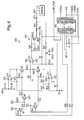
- Another difference between the circuit 400 of Fig. 4 and the circuit 300 of Fig. 3 is that the operational amplifier U1D and its associated components have been removed and the low side of the resistor RG has been connected directly to ground.
- Fig. 5 depicts an interface circuit 500 that is similar to the circuit 400, with the exception that the circuit 500 operates in the voltage mode, i.e., a voltage across the sensor is measured to determine a sensor current.
- Fig. 5A shows exemplary signals associated with the circuit 500.
- a non-inverting input of a unity gain operational amplifier U1E is coupled through a 10K ohm resistor to an input of the sensor S1.
- An output of the amplifier U1E is coupled to an input of the microcontroller U2C, such that the microcontroller U2C can determine the voltage across the sensor S1.
- a matched pair of pull-up and pull-down constant current sources may be utilized to determine the impedance of a sensor.
- a method and system have been described herein that advantageously provide a less expensive, less error prone technique for determining the impedance of a sensor, e.g., a zeolite-based ammonia sensor, that may experience ion migration.
Landscapes
- Chemical & Material Sciences (AREA)
- Health & Medical Sciences (AREA)
- Life Sciences & Earth Sciences (AREA)
- Analytical Chemistry (AREA)
- General Health & Medical Sciences (AREA)
- Pathology (AREA)
- Immunology (AREA)
- Physics & Mathematics (AREA)
- Engineering & Computer Science (AREA)
- Biochemistry (AREA)
- General Physics & Mathematics (AREA)
- Combustion & Propulsion (AREA)
- Medicinal Chemistry (AREA)
- Food Science & Technology (AREA)
- Chemical Kinetics & Catalysis (AREA)
- Electrochemistry (AREA)
- Investigating Or Analyzing Materials By The Use Of Electric Means (AREA)
Applications Claiming Priority (4)
| Application Number | Priority Date | Filing Date | Title |
|---|---|---|---|
| US966910 | 1992-10-27 | ||
| US52936803P | 2003-12-12 | 2003-12-12 | |
| US529368P | 2003-12-12 | ||
| US10/966,910 US20050127920A1 (en) | 2003-12-12 | 2004-10-15 | Method and system for impedance measurement of a zeolite-based ammonia sensor |
Publications (1)
| Publication Number | Publication Date |
|---|---|
| EP1541997A1 true EP1541997A1 (de) | 2005-06-15 |
Family
ID=34527138
Family Applications (1)
| Application Number | Title | Priority Date | Filing Date |
|---|---|---|---|
| EP04078339A Withdrawn EP1541997A1 (de) | 2003-12-12 | 2004-12-09 | Verfahren und System zur Messung der Impedanz eines Ammoniaksensors auf Zeolithbasis |
Country Status (2)
| Country | Link |
|---|---|
| US (1) | US20050127920A1 (de) |
| EP (1) | EP1541997A1 (de) |
Families Citing this family (6)
| Publication number | Priority date | Publication date | Assignee | Title |
|---|---|---|---|---|
| DE10102237A1 (de) * | 2001-01-19 | 2002-08-08 | Bosch Gmbh Robert | Vorrichtung zur Dosierung einer Harnstofflösung |
| US7411402B2 (en) * | 2005-08-17 | 2008-08-12 | Delphi Technologies, Inc. | Technique for reducing a parasitic DC bias voltage on a sensor |
| US9038373B2 (en) | 2010-05-03 | 2015-05-26 | Cummins Inc. | Ammonia sensor control of an SCR aftertreatment system |
| US8640448B2 (en) | 2010-05-03 | 2014-02-04 | Cummins Inc. | Transient compensation control of an SCR aftertreatment system |
| US9476338B2 (en) | 2010-05-03 | 2016-10-25 | Cummins Inc. | Ammonia sensor control, with NOx feedback, of an SCR aftertreatment system |
| WO2016077755A1 (en) | 2014-11-13 | 2016-05-19 | Ohio State Innovation Foundation | Membranes for fluid separation |
Citations (4)
| Publication number | Priority date | Publication date | Assignee | Title |
|---|---|---|---|---|
| DE3625071A1 (de) * | 1986-04-05 | 1987-10-08 | Bosch Gmbh Robert | Verfahren zum betreiben eines sensors und vorrichtung zur durchfuehrung des verfahrens |
| US6069013A (en) * | 1997-02-01 | 2000-05-30 | Dornier Gmbh | Sensor for the selective detection of ammonia in noX -containing, oxygen-rich gases |
| US6067841A (en) * | 1997-04-25 | 2000-05-30 | Denso Corporation | Method of detecting element resistance of gas concentration sensor |
| US20010000956A1 (en) * | 1998-01-16 | 2001-05-10 | Denso Corporation | Resistance component detecting apparatus for an oxygen concentration sensor and oxygen-concentration detecting apparatus |
Family Cites Families (5)
| Publication number | Priority date | Publication date | Assignee | Title |
|---|---|---|---|---|
| US4793175A (en) * | 1986-04-05 | 1988-12-27 | Robert Bosch Gmbh | Humidity sensor, sensor material, method of manufacture and humidity sensing system, especially for automotive use |
| US5547552A (en) * | 1994-06-20 | 1996-08-20 | Nippondenso Co., Ltd. | Oxygen concentration detecting apparatus |
| GB2301901B (en) * | 1995-06-05 | 1999-04-07 | Nippon Denso Co | Apparatus and method for diagnosing degradation or malfunction of oxygen sensor |
| JPH116813A (ja) * | 1997-04-23 | 1999-01-12 | Denso Corp | ガス濃度センサの制御装置 |
| EP1403637B1 (de) * | 2002-09-25 | 2010-05-12 | NGK Spark Plug Co. Ltd. | Ammoniak Sensor |
-
2004
- 2004-10-15 US US10/966,910 patent/US20050127920A1/en not_active Abandoned
- 2004-12-09 EP EP04078339A patent/EP1541997A1/de not_active Withdrawn
Patent Citations (4)
| Publication number | Priority date | Publication date | Assignee | Title |
|---|---|---|---|---|
| DE3625071A1 (de) * | 1986-04-05 | 1987-10-08 | Bosch Gmbh Robert | Verfahren zum betreiben eines sensors und vorrichtung zur durchfuehrung des verfahrens |
| US6069013A (en) * | 1997-02-01 | 2000-05-30 | Dornier Gmbh | Sensor for the selective detection of ammonia in noX -containing, oxygen-rich gases |
| US6067841A (en) * | 1997-04-25 | 2000-05-30 | Denso Corporation | Method of detecting element resistance of gas concentration sensor |
| US20010000956A1 (en) * | 1998-01-16 | 2001-05-10 | Denso Corporation | Resistance component detecting apparatus for an oxygen concentration sensor and oxygen-concentration detecting apparatus |
Also Published As
| Publication number | Publication date |
|---|---|
| US20050127920A1 (en) | 2005-06-16 |
Similar Documents
| Publication | Publication Date | Title |
|---|---|---|
| US6546720B2 (en) | Method and apparatus for controlling the amount of reactant to be added to a substance using a sensor which is responsive to both the reactant and the substance | |
| US9658177B2 (en) | Apparatus, system, and method for catalyst presence detection | |
| CA2612428C (en) | Method of sensor conditioning for improving signal output stability for mixed gas measurements | |
| US7909970B2 (en) | Controller for gas concentration sensor | |
| CN111263848A (zh) | 用于操作柴油发动机的废气后处理系统的方法和废气后处理系统 | |
| US20120186329A1 (en) | Particle sensor, exhaust system and method for determining particles in the exhaust gas | |
| US20090078587A1 (en) | Method of Sensor Conditioning for Improving Signal Output Stability for Mixed Gas Measurements | |
| CN102817684B (zh) | 用于排气系统NOx传感器的过滤器的诊断方法和诊断模块 | |
| EP1541997A1 (de) | Verfahren und System zur Messung der Impedanz eines Ammoniaksensors auf Zeolithbasis | |
| Kato et al. | Performance of thick film NOx sensor on diesel and gasoline engines | |
| JP2001004444A (ja) | スイッチング式ndirシステム | |
| US7043957B2 (en) | Element impedance detection apparatus and method for oxygen sensor | |
| JP2000329730A (ja) | 酸素濃度センサの素子インピーダンス検出方法及び素子インピーダンス検出装置 | |
| Surenahalli | Dynamic model based state estimation in a heavy duty diesel aftertreatment system for onboard diagnostics and controls | |
| CN102628831A (zh) | 用于监控化学敏感场效应晶体管的至少一种功能的方法和监控设备 | |
| JP2003504565A (ja) | 触媒システムの状態検出方法 | |
| EP1134580B1 (de) | Methode und Schaltkreis zum Überwachen und Diagnostizieren eines Sauerstoffsensors | |
| KR102491742B1 (ko) | 전기 회로 및 전기 부하에 대한 진단 방법 | |
| US11448568B2 (en) | Method of determining the evaluation time for a diagnosis | |
| JPH09125937A (ja) | 触媒劣化判定方法及び装置 | |
| US7411402B2 (en) | Technique for reducing a parasitic DC bias voltage on a sensor | |
| CN115263504A (zh) | 一种传感器可信性判断方法及装置 | |
| CN108956862B (zh) | 用于识别在传感器中断开线路的出现的方法 | |
| Bleicker et al. | NOx Sensor for Commercial Vehicles and Mobile Machines | |
| JPH11174020A (ja) | A/fセンサの制御回路 |
Legal Events
| Date | Code | Title | Description |
|---|---|---|---|
| PUAI | Public reference made under article 153(3) epc to a published international application that has entered the european phase |
Free format text: ORIGINAL CODE: 0009012 |
|
| AK | Designated contracting states |
Kind code of ref document: A1 Designated state(s): AT BE BG CH CY CZ DE DK EE ES FI FR GB GR HU IE IS IT LI LT LU MC NL PL PT RO SE SI SK TR |
|
| AX | Request for extension of the european patent |
Extension state: AL BA HR LV MK YU |
|
| 17P | Request for examination filed |
Effective date: 20051215 |
|
| AKX | Designation fees paid |
Designated state(s): AT BE BG CH CY CZ DE DK EE ES FI FR GB GR HU IE IS IT LI LT LU MC NL PL PT RO SE SI SK TR |
|
| STAA | Information on the status of an ep patent application or granted ep patent |
Free format text: STATUS: THE APPLICATION IS DEEMED TO BE WITHDRAWN |
|
| 18D | Application deemed to be withdrawn |
Effective date: 20070703 |