EP1541873A1 - Verfahren und Einrichtung zur Vorgabe einer Betriebsgeschwindigkeit eines fluidbetätigten Antriebes - Google Patents
Verfahren und Einrichtung zur Vorgabe einer Betriebsgeschwindigkeit eines fluidbetätigten Antriebes Download PDFInfo
- Publication number
- EP1541873A1 EP1541873A1 EP03028040A EP03028040A EP1541873A1 EP 1541873 A1 EP1541873 A1 EP 1541873A1 EP 03028040 A EP03028040 A EP 03028040A EP 03028040 A EP03028040 A EP 03028040A EP 1541873 A1 EP1541873 A1 EP 1541873A1
- Authority
- EP
- European Patent Office
- Prior art keywords
- throttle
- operating
- setting
- throttles
- values
- Prior art date
- Legal status (The legal status is an assumption and is not a legal conclusion. Google has not performed a legal analysis and makes no representation as to the accuracy of the status listed.)
- Granted
Links
- 239000012530 fluid Substances 0.000 title claims abstract description 31
- 238000000034 method Methods 0.000 title claims abstract description 7
- 230000000007 visual effect Effects 0.000 claims description 4
- 230000011664 signaling Effects 0.000 claims description 3
- 230000033001 locomotion Effects 0.000 description 5
- 238000010276 construction Methods 0.000 description 2
- 238000009434 installation Methods 0.000 description 2
- 238000004891 communication Methods 0.000 description 1
- 230000001627 detrimental effect Effects 0.000 description 1
- 238000007599 discharging Methods 0.000 description 1
- 230000010354 integration Effects 0.000 description 1
- 230000008092 positive effect Effects 0.000 description 1
- 239000007858 starting material Substances 0.000 description 1
- 230000007704 transition Effects 0.000 description 1
Images
Classifications
-
- F—MECHANICAL ENGINEERING; LIGHTING; HEATING; WEAPONS; BLASTING
- F15—FLUID-PRESSURE ACTUATORS; HYDRAULICS OR PNEUMATICS IN GENERAL
- F15B—SYSTEMS ACTING BY MEANS OF FLUIDS IN GENERAL; FLUID-PRESSURE ACTUATORS, e.g. SERVOMOTORS; DETAILS OF FLUID-PRESSURE SYSTEMS, NOT OTHERWISE PROVIDED FOR
- F15B13/00—Details of servomotor systems ; Valves for servomotor systems
- F15B13/02—Fluid distribution or supply devices characterised by their adaptation to the control of servomotors
- F15B13/06—Fluid distribution or supply devices characterised by their adaptation to the control of servomotors for use with two or more servomotors
- F15B13/08—Assemblies of units, each for the control of a single servomotor only
- F15B13/0803—Modular units
-
- F—MECHANICAL ENGINEERING; LIGHTING; HEATING; WEAPONS; BLASTING
- F15—FLUID-PRESSURE ACTUATORS; HYDRAULICS OR PNEUMATICS IN GENERAL
- F15B—SYSTEMS ACTING BY MEANS OF FLUIDS IN GENERAL; FLUID-PRESSURE ACTUATORS, e.g. SERVOMOTORS; DETAILS OF FLUID-PRESSURE SYSTEMS, NOT OTHERWISE PROVIDED FOR
- F15B11/00—Servomotor systems without provision for follow-up action; Circuits therefor
- F15B11/02—Systems essentially incorporating special features for controlling the speed or actuating force of an output member
- F15B11/04—Systems essentially incorporating special features for controlling the speed or actuating force of an output member for controlling the speed
- F15B11/0413—Systems essentially incorporating special features for controlling the speed or actuating force of an output member for controlling the speed in one direction only, with no control in the reverse direction, e.g. check valve in parallel with a throttle valve
-
- F—MECHANICAL ENGINEERING; LIGHTING; HEATING; WEAPONS; BLASTING
- F15—FLUID-PRESSURE ACTUATORS; HYDRAULICS OR PNEUMATICS IN GENERAL
- F15B—SYSTEMS ACTING BY MEANS OF FLUIDS IN GENERAL; FLUID-PRESSURE ACTUATORS, e.g. SERVOMOTORS; DETAILS OF FLUID-PRESSURE SYSTEMS, NOT OTHERWISE PROVIDED FOR
- F15B11/00—Servomotor systems without provision for follow-up action; Circuits therefor
- F15B11/02—Systems essentially incorporating special features for controlling the speed or actuating force of an output member
- F15B11/04—Systems essentially incorporating special features for controlling the speed or actuating force of an output member for controlling the speed
- F15B11/042—Systems essentially incorporating special features for controlling the speed or actuating force of an output member for controlling the speed by means in the feed line, i.e. "meter in"
-
- F—MECHANICAL ENGINEERING; LIGHTING; HEATING; WEAPONS; BLASTING
- F16—ENGINEERING ELEMENTS AND UNITS; GENERAL MEASURES FOR PRODUCING AND MAINTAINING EFFECTIVE FUNCTIONING OF MACHINES OR INSTALLATIONS; THERMAL INSULATION IN GENERAL
- F16K—VALVES; TAPS; COCKS; ACTUATING-FLOATS; DEVICES FOR VENTING OR AERATING
- F16K37/00—Special means in or on valves or other cut-off apparatus for indicating or recording operation thereof, or for enabling an alarm to be given
- F16K37/0008—Mechanical means
- F16K37/0016—Mechanical means having a graduated scale
-
- G—PHYSICS
- G05—CONTROLLING; REGULATING
- G05D—SYSTEMS FOR CONTROLLING OR REGULATING NON-ELECTRIC VARIABLES
- G05D7/00—Control of flow
- G05D7/01—Control of flow without auxiliary power
- G05D7/0186—Control of flow without auxiliary power without moving parts
Definitions
- the invention relates to a method and a device for Specification of an operating speed of a fluid-operated Drive.
- Fluid operated drives be a pneumatic or hydraulic Drives are in the art in many ways Variants especially as linear drives and as Rotary actuators known. They usually contain one for the Force tap suitable movable output part, for example as a piston rod or, in the case of rodless drives, designed as a movable carriage. To create the driving forces is a motion coupled with the driven part Piston pressurized fluid under pressure.
- the operating speed of the fluid-operated Drive that is the speed of the process Stripping section, is responsible among other things, the flow rate, with the fluid or pressure medium supplied or removed becomes.
- a fluid-operated drive for this purpose equipped with a variably adjustable throttle, which in the fluid connection is turned on and on, for example an adjusting screw is located, with the desired flow rate by adjusting the throttle value pretend.
- the throttle remains after the made Adjustment on the drive.
- Throttling values have - also as fixed or fixed throttles - in which a change in the given throttle value not possible.
- the problem is that when setting up the operation of a machine has no way the fluid-operated drives used with regard to their Operating speed variable to adapt to the circumstances.
- the object is achieved by a device for Specification of the operating speed of a fluid-operated drive, with at least one solvable in the one concerned Drive leading fluid connection switchable setting device, the one adjusting throttle with variably adjustable Throttling and having a reporting device is equipped, which is a currently set throttle value corresponding target reference value outputs, and with a plurality of each instead of the setting device in the fluid connection switchable operating throttles over in gradations different from each other, fixed predetermined Throttling and each have a the fixed predetermined throttle value corresponding actual reference value is assigned, the throttle values of the Throttle and the operating throttles corresponding to each other Set and actual reference values agree, so that after replacing the setting device by one in the reference value matching operating throttle by the Retain setting device set operating speed remains.
- variable setting options an adjustable throttle with the security features of a Fixed throttle combined.
- the setting device that has a as Throttle throttle referred to, in which the Variably set available throttle values can be.
- Has to find and set the desired operating speed If you change the setting device by a as operating throttle designated fixed throttle, whose fixed predetermined Throttling value corresponds to that previously with the setting throttle has been set.
- Reference values wherein a plurality of graduated with one another Throttling values of operating throttles fitted is provided, from which one as a replacement for the Setting device can select suitable operating choke.
- the Reference values do not necessarily have to be numeric but correspond to realized flow rates can be any other matched values.
- the flexibility in setting the desired operating speed The finer is the gradation between the fixed throttle values of the provided Operating throttles is. Conveniently the more different operating throttles are available, the finer the graduation is chosen. As advantageous it is currently viewed by an appropriate number of operational throttles about 30 to 50 different, steady to provide predetermined flow levels.
- One to output the set operating speed corresponding target reference value serving signaling device is particularly as an immediate part of Setting device executed. It would be conceivable by data linkage via wirelessly transmitted Signals a largely automated identification the operating choke suitable as a replacement for the setting device cause.
- this is designed as a display device, the one Immediate visual recognition of the set nominal reference value allows, then by simple visual comparison with the appropriately marked operating throttles the necessary selection can be made.
- the operating throttles with their actual reference values numbered while the display device numerically displays the required reference reference value.
- alphanumeric references would also be possible.
- color coding could also be used become.
- the display device equipped with a scale from which the obtained Reference reference value is readable is readable.
- the operating throttles can be very simple, since they have no Verstellmimiken for influencing the throttle value need.
- Operating throttles are provided in a modular manner. This happens in particular in that a plurality of accordingly formed the different throttle values Throttling units is provided and that further a lower number of standardized trained, switching on in the fluid connection gestattender terminal units is provided, so that an operating throttle each off one of the standardized connection units and one of the Assemble throttling units.
- Both the setting throttle and the operating throttles can If necessary, have a check valve that the throttle means responsible for setting the throttle value is connected in parallel. In this way it is achieved that the pressure medium only in one direction of flow is throttled while in the opposite flow direction an unthrottled flow with a higher flow rate is possible.
- the setting device and the operating throttles and the or If necessary existing tools are expediently in one portable container provided, which is easy between the different locations.
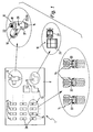
- FIG. 1 shows a total reference numeral 1 Speed setting device, with the help of the Possibility exists, the operating speed of a in figures
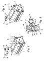
- FIGS. 2 and 4 exemplarily illustrate fluid actuated drive 2 variable to specify.
- the illustrated fluid actuated drive 2 is one with compressed air actuatable linear drive. It would be possible, however an embodiment as a rotary drive and / or an operation with a hydraulic fluid as drive medium.
- the drive 2 has a housing 3 in which a dot-dash line indicated piston 4 is accommodated by the fluid force is linearly displaceable.
- the piston 4 is an example as a piston rod designed driven part 5 motion coupled, that participates in the movement of the piston 4.
- the Piston 4 divides the interior of the housing 3 into two working spaces, each with a the housing 3 passing through Fluid channel 6a, 6b are in communication.
- By means of an the respective fluid channel 6a, 6b connected in the Drawing only dash-dotted lines indicated fluid connection 7a, 7b may fluidic pressure medium in the respective Working space fed or from the respective work space be dissipated.
- the piston 4 to a Linear motion are driven, located at the output part 5 tap, for example, a component to operate a machine.
- the traversing speed of the Abtriebsteils 5, the operating speed of the fluid-operated Drive 2 corresponds depends significantly on the flow rate of the inflowing or outflowing fluid from. With other words, it is possible by specifying different Flow rates the operating speed of the fluid-operated drive 2, that is, in the embodiment the travel speed of the driven part 5, to vary.
- speed setting device 1 can be the Set operating speed of drive 2 as required. At the same time, they can guarantee that the attitude taken no longer by unauthorized Personal or even accidentally changed. Such changes would be detrimental to the coordination the fluid-operated drive 2 with other drives and would ultimately have the function of one with several Drives equipped machine can affect.
- the speed setting device 1 consists of several Components together. Some of these components are in Figure 1 in oval frames again enlarged individually shown.
- the speed setting device 1 initially contains a portable container 8, in which the functional components the speed setting device 1 housed are.
- As essential functional components has the speed setting device 1 via at least one setting device 12 and a plurality of operating throttles 13, wherein the latter in the embodiment in the manner of a modular system are provided and different from case to case in the container 8 provided components to assemble.
- a ready-to-use operating choke 13 is shown in FIGS. 3 and 4, respectively.
- the components of the operating throttles belonging to the modular system 13 are on the one hand a plurality of throttling units 14 and on the other several terminal units 15. From one each Throttling unit 14 and a connection unit 15 leaves an operating throttle 13 in particular assemble without tools.
- the setting device 12 has a first device connection 16 and a second device port 17.
- the first Device connection 16 is connected to the housing 3 of the drive. 2 provided connection openings 9a, 9b of the fluid channels 6a, 6b adjusted so that it is fixed there under seal can be.
- the second device connection 17 is formed around a fluid line belonging to the fluid connection 7a, For example, a compressed air hose, releasably connect to can. In this way it is possible, the setting 12th so as to attach to the housing 3 of the fluid-operated drive 2, that it is switched on in the fluid connection 7a.
- a Message device 23 is provided, the one currently set reference value corresponding "SR" outputs.
- the reporting device 23 executed as a display device 23 a, which is an immediate visual recognition or reading of the set Target reference value enabled.
- the display device 23a is so executed to numerically display the reference reference values.
- Throttling values are set, which then each a readable reference reference value "SR" corresponds.
- SR readable reference reference value
- the reference value the number "20" displayed.
- the operating throttles 13 In contrast to the adjusting throttle 18 of the setting 12th are the operating throttles 13 together and especially as fixed chokes or fixed chokes formed, each invariably over have fixed throttle values.
- the respective Throttling value is in the preferred modular type Solution given by the individual throttling units 14, while the terminal units 15 the throttling intensity do not influence and therefore have a standardized, can have identical structure with each other.
- Each operating throttle 13 is a fixed throttle value corresponding actual reference value "IR" assigned.
- This actual reference value assignment is done in the embodiment in terms of differing from each other Throttling units 14.
- the actual reference value "IR” is expediently noted directly on the operating throttles 13 and found in the embodiment as a print or Imprint on the individual throttling units 14.
- the container 8 in the area of in him provided recordings for the throttling units be marked with the actual reference values.
- a preferred construction is one of a throttling unit 14 and a terminal unit 15 assembled Operating throttle 13 forth. It contains a throttling unit 14, the one executed in the manner of a hollow screw Base body 24, on which the connection unit 15 is attached with a sleeve-like bearing part 25. Of the Foot portion of the body 24 protrudes over the bearing part 25th and forms a first throttle port 26, the so is formed so that it is sealed to a connection opening 9 of the housing 3 of the drive 2 can be fixed. It is provided in particular that the first throttle connection 26 has an external thread, which according to Figure 4 a screwing in the connection opening 9 allows. To screw in to assist with a tool is the head section 28 of the main body 24 with an example as Hexagon contoured tool attack part equipped.
- a second throttle connection 27 away. He is trained to a fluid line, For example, a pressure medium hose, under seal releasably fixable. While the design of the first Throttle terminal 26 of those of the first device connection 16 of the setting 12 corresponds, is the second throttle connection 27 in a similar way as the second device connection 17 of the setting device 12 is formed.
- a throttle channel extends 32. This connects the first throttle port 26 with the second throttle port 27 and includes a throttle point 33, at which the narrowest channel cross-section of the throttle channel 32 is located.
- the throttle channel 32 has an in the throttle unit 14 extending first throttle channel section 34 and an associated, in the connection unit 15 extending second throttle channel section 35th
- This two throttle channel sections 34, 35 communicate with each other in the transition region between the bearing part 25 and the Base 24.
- the fluidic connection is independent given by the angular position of the connection unit 15, with respect to the longitudinal axis 36 of the throttling unit 14 is rotatable relative to this.
- the throttling means formed by the throttle body 33 of the Operating throttle 13 connected in parallel is a convenient a flexible lip as a valve member having check valve 37.
- the pressure medium can be the operating throttle 13 in one direction unthrottled and unhindered flow through while forced in the opposite direction is to pass the throttle body 33.
- the reverse direction the check valve 37 depends on the installation direction of the valve member from.
- the structure of the setting 12 correspond to that of the operating throttles 13.
- the setting device 12 equipped with a check valve 37 there is the possibility of the setting device 12 equipped with a check valve 37, the then the Einstelldrossel 18 operatively connected in parallel is.
- the throttling units 14 are for Specification of the desired different fixed throttle values with correspondingly differently dimensioned throttle channel cross sections Mistake. From Figure 1 is good here can be seen how the different throttle channel cross sections by local throttles 33 with different Have flow cross sections realized.
- the described speed setting device 1 leaves particularly advantageous in the following Insert fashion. It is assumed that the task This is the retraction speed of the driven part 5 or the time that elapses until the Stripping part 5 of the extended shown in the drawing Position moved back to the retracted position is.
- the fluid connection 7a is a setting 12th switched on, in a flow direction from the first device connection 16 to the second device port 17 throttles, in the opposite direction, however, due to the integrated and in FIG 1 dash-dotted lines indicated check valve 37 a allows free passage.
- the setting device 12 is doing so with its first device port 16 at the designated Connection opening 9a of the housing 3 of the drive. 2 fixed.
- the other connection opening 9b is at another Connected fluid connection 7b, in which no setting device 12 is turned on.
- the two fluid connection 7a, 7b are with a control valve device, not shown associated with alternating feeding and discharging of print medium allows.
- the output part 5 is now through the aforementioned fluid admission alternately in the entrance and moved in the outward direction.
- the setting throttle 18 is the retraction speed of the driven part 5 is set to the desired level. If the desired traversing speed is found, At the display device 23a, the indicated reference reference value is displayed Read "SR".
- the fluid-operated drive 2 is ultimately with an operating throttle 13 designed as a fixed throttle whose throttling value corresponds to that for the operation of the fluid-operated drive 2 desired value corresponds.
- this value using the setting 12 very it has been set exactly and variably, it can not now be changed easily. This leads to a very high Operational safety of the drive.
- connection openings 9a, 9b of the drive 2 each have a setting device 12 to install a simultaneous setting of both the retraction speed and the retraction speed of the drive.
- the selected operating choke was selected 13 of a terminal unit 15 and a with identified the corresponding actual reference value "IR" Throttling unit 14 composed.
- the modular Construction has the advantage that one of the connection units 15 only one of the maximum to be realized number of Operating throttles 13 provide appropriate number must, resulting in a significant cost savings results.
- the speed setting device 1 instead of just one with several at the same time Setting devices 12 may be equipped, which then alternatively can be used.
- both the setting device 12 and the operating throttles 13 would also be possible, for example, for alphanumeric identification or any other type of coding, for example using different color patterns.
- the setting device 12 could also be provided with a combination of scale and pointer.
- the numerical display on the setting device 12 can, for example be realized by means of a counter.
- the speed setting device 1 may be, for example realized as a starter set with a certain basic equipment with the user having the option when needed to re-order further operating throttles 13 and / or setting devices 12, if the existing number is no longer sufficient should or if other throttling intensities are covered should be.
Landscapes
- Engineering & Computer Science (AREA)
- General Engineering & Computer Science (AREA)
- Physics & Mathematics (AREA)
- Mechanical Engineering (AREA)
- Fluid Mechanics (AREA)
- Fluid-Pressure Circuits (AREA)
- General Physics & Mathematics (AREA)
- Automation & Control Theory (AREA)
Abstract
Description
- Figur 1
- in schematischer Darstellung eine bevorzugte Bauform einer zur Vorgabe der Betriebsgeschwindigkeit eines fluidbetätigten Antriebes geeigneten Einrichtung,
- Figur 2
- eine Verwendung des Einstellgerätes an einem fluidbetätigten Antrieb,
- Figur 3
- eine entsprechend der Verwendung des Einstellgerätes ausgewählt Betriebsdrossel im Längsschnitt, und
- Figur 4
- den fluidbetätigten Antrieb aus Figur 2, wobei das in Figur 2 eingesetzte Einstellgerät durch die in Figur 3 gezeigte Betriebsdrossel ersetzt ist.
Zum Ablesen der Soll-Referenzwerte könnte das Einstellgerät 12 auch mit einer Kombination aus Skala und Zeiger versehen sein.
Claims (11)
- Verfahren zur Vorgabe einer Betriebsgeschwindigkeit eines fluidbetätigten Antriebes (2), wobei man ein eine Einstelldrossel (18) mit variabel einstellbaren Drosselungswerten aufweisendes Einstellgerät (12) in eine zum betreffenden Antrieb (2) führende Fluidverbindung (7a) einschaltet und durch Verstellen der Einstelldrossel (18) die gewünschte Betriebsgeschwindigkeit einstellt, wonach man anhand eines durch das Einstellgerät (12) entsprechend dem eingestellten Drosselungswert zur Verfügung gestellten Soll-Referenzwertes aus einer Mehrzahl bereitgestellter Betriebsdrosseln, die über sich in Abstufungen voneinander unterscheidende, fest vorgegebene Drosselungswerte verfügen und mit entsprechenden Ist-Referenzwerten identifiziert sind, diejenige Betriebdrossel auswählt, deren fest vorgegebener Drosselungswert dem an dem Einstellgerät eingestellten Drosselungswert entspricht, wonach man das Einstellgerät durch ausgewählte Betriebsdrosseln ersetzt.
- Einrichtung zur Vorgabe einer Betriebsgeschwindigkeit eines fluidbetätigten Antriebes, mit mindestens einem lösbar in die zum betreffenden Antrieb (2) führende Fluidverbindung (7a) einschaltbaren Einstellgerät (12), das eine Einstelldrossel (18) mit variabel einstellbaren Drosselungswerten aufweist und das mit einer Meldeeinrichtung (23) ausgestattet ist, die einen dem momentan eingestellten Drosselungswert entsprechenden Soll-Referenzwert ausgibt, und mit einer Mehrzahl von jeweils anstelle des Einstellgerätes (12) in die Fluidverbindung (7a) einschaltbaren Betriebsdrosseln (13), die über sich in Abstufungen voneinander unterscheidende, fest vorgegebene Drosselungswerte verfügen und denen jeweils ein dem fest vorgegebenen Drosselungswert entsprechender Ist-Referenzwert zugeordnet ist, wobei die Drosselungswerte der Einstelldrossel (18) und der Betriebsdrosseln (13) bei einander entsprechenden Soll- und Ist-Referenzwerten übereinstimmen, so dass nach dem Ersetzen des Einstellgerätes (12) durch eine im Referenzwert übereinstimmende Betriebsdrossel (13) die durch das Einstellgerät (12) eingestellte Betriebsgeschwindigkeit beibehalten bleibt.
- Einrichtung nach Anspruch 2, dadurch gekennzeichnet, dass die Meldeeinrichtung (23) eine ein unmittelbares visuelles Erkennen des eingestellten Soll-Referenzwertes ermöglichende Anzeigeeinrichtung (23a) ist.
- Einrichtung nach Anspruch 3, dadurch gekennzeichnet, dass die Anzeigeeinrichtung (23a) die Soll-Referenzwerte numerisch oder alphanumerisch anzeigt.
- Einrichtung nach einem der Ansprüche 2 bis 4, dadurch gekennzeichnet, dass die Meldeeinrichtung (23) unmittelbar an dem Einstellgerät (12) vorgesehen ist.
- Einrichtung nach einem der Ansprüche 2 bis 5, dadurch gekennzeichnet, dass die Ist-Referenzwerte unmittelbar an den Betriebsdrosseln (13) vermerkt sind.
- Einrichtung nach einem der Ansprüche 2 bis 6, dadurch gekennzeichnet, dass die Betriebsdrosseln (13) zur festen Vorgabe des jeweiligen Drosselungswertes einen Drosselkanal (32) mit entsprechend dimensioniertem Kanalquerschnitt aufweisen.
- Einrichtung nach einem der Ansprüche 2 bis 7, dadurch gekennzeichnet, dass die Betriebsdrosseln (13) baukastenartig bereitgestellt sind, indem eine Mehrzahl von entsprechend den unterschiedlichen Drosselungswerten ausgebildeten Drosselungseinheiten (14) vorgesehen ist, die sich mit standardisierten Anschlusseinheiten (15) zu jeweils einer Betriebsdrossel (13) kombinieren lassen.
- Einrichtung nach einem der Ansprüche 2 bis 8, dadurch gekennzeichnet, dass die Einstelldrossel (18) und/oder die Betriebsdrosseln (13) ein den Drosselmitteln (33) parallel geschaltetes Rückschlagventil (37) beinhalten.
- Einrichtung nach einem der Ansprüche 2 bis 9, gekennzeichnet durch einen tragbaren Behälter (8), in dem das Einstellgerät (12) und die Betriebsdrosseln (13) entnehmbar bereitgestellt werden.
- Einrichtung nach einem der Ansprüche 2 bis 10 zur Verwendung bei der Durchführung des Verfahrens gemäß Anspruch 1.
Priority Applications (3)
| Application Number | Priority Date | Filing Date | Title |
|---|---|---|---|
| AT03028040T ATE331892T1 (de) | 2003-12-08 | 2003-12-08 | Verfahren und einrichtung zur vorgabe einer betriebsgeschwindigkeit eines fluidbetätigten antriebes |
| DE50304078T DE50304078D1 (de) | 2003-12-08 | 2003-12-08 | Verfahren und Einrichtung zur Vorgabe einer Betriebsgeschwindigkeit eines fluidbetätigten Antriebes |
| EP03028040A EP1541873B1 (de) | 2003-12-08 | 2003-12-08 | Verfahren und Einrichtung zur Vorgabe einer Betriebsgeschwindigkeit eines fluidbetätigten Antriebes |
Applications Claiming Priority (1)
| Application Number | Priority Date | Filing Date | Title |
|---|---|---|---|
| EP03028040A EP1541873B1 (de) | 2003-12-08 | 2003-12-08 | Verfahren und Einrichtung zur Vorgabe einer Betriebsgeschwindigkeit eines fluidbetätigten Antriebes |
Publications (2)
| Publication Number | Publication Date |
|---|---|
| EP1541873A1 true EP1541873A1 (de) | 2005-06-15 |
| EP1541873B1 EP1541873B1 (de) | 2006-06-28 |
Family
ID=34486124
Family Applications (1)
| Application Number | Title | Priority Date | Filing Date |
|---|---|---|---|
| EP03028040A Expired - Lifetime EP1541873B1 (de) | 2003-12-08 | 2003-12-08 | Verfahren und Einrichtung zur Vorgabe einer Betriebsgeschwindigkeit eines fluidbetätigten Antriebes |
Country Status (3)
| Country | Link |
|---|---|
| EP (1) | EP1541873B1 (de) |
| AT (1) | ATE331892T1 (de) |
| DE (1) | DE50304078D1 (de) |
Citations (3)
| Publication number | Priority date | Publication date | Assignee | Title |
|---|---|---|---|---|
| FR1025206A (fr) * | 1949-10-29 | 1953-04-13 | Standard Oil Dev Co | Plaque à orifice indicatrice pour raccords de tuyaux filetés |
| US3334654A (en) * | 1965-09-27 | 1967-08-08 | Deltrol Corp | Operating and read-out means for needle valves and the like |
| DE2741672A1 (de) * | 1977-09-16 | 1979-03-22 | Gerhard Fischer | Vorrichtung zur anzeige der verstellbewegungen zwischen zwei gegeneinander verdrehbaren bauteilen |
-
2003
- 2003-12-08 DE DE50304078T patent/DE50304078D1/de not_active Expired - Lifetime
- 2003-12-08 EP EP03028040A patent/EP1541873B1/de not_active Expired - Lifetime
- 2003-12-08 AT AT03028040T patent/ATE331892T1/de not_active IP Right Cessation
Patent Citations (3)
| Publication number | Priority date | Publication date | Assignee | Title |
|---|---|---|---|---|
| FR1025206A (fr) * | 1949-10-29 | 1953-04-13 | Standard Oil Dev Co | Plaque à orifice indicatrice pour raccords de tuyaux filetés |
| US3334654A (en) * | 1965-09-27 | 1967-08-08 | Deltrol Corp | Operating and read-out means for needle valves and the like |
| DE2741672A1 (de) * | 1977-09-16 | 1979-03-22 | Gerhard Fischer | Vorrichtung zur anzeige der verstellbewegungen zwischen zwei gegeneinander verdrehbaren bauteilen |
Non-Patent Citations (1)
| Title |
|---|
| "CARTRIDGE VALVES PROVIDE DROP-IN FLEXIBILITY A STAFF REPORT", HYDRAULICS AND PNEUMATICS, INDUSTRIAL PUBLISHING CORP. CLEVELAND, US, vol. 54, no. 4, April 2001 (2001-04-01), pages 35 - 38,82, XP001043676, ISSN: 0018-814X * |
Also Published As
| Publication number | Publication date |
|---|---|
| ATE331892T1 (de) | 2006-07-15 |
| EP1541873B1 (de) | 2006-06-28 |
| DE50304078D1 (de) | 2006-08-10 |
Similar Documents
| Publication | Publication Date | Title |
|---|---|---|
| DE2053819A1 (de) | Druckluftzylinder-Einheit | |
| EP1350960B1 (de) | Fluidbetätigte Antriebsvorrichtung | |
| DE4108158A1 (de) | Linear-antriebsvorrichtung | |
| EP1249619B1 (de) | Ventileinheit mit entsperrbarem Rückschlagventil und damit ausgestatteter fluidbetätigter Antrieb | |
| DE1965536A1 (de) | Messzylinder | |
| DE69408310T2 (de) | Bohranornung und vorschubvorrichtung | |
| EP1387971B1 (de) | Schieberventil | |
| DE3642642C3 (de) | Schaltungsanordnung zur Lage- und Vorschubregelung eines hydraulischen Antriebes | |
| DE10350305B4 (de) | Fluidbetätigte Drehantriebsvorrichtung | |
| EP1541873B1 (de) | Verfahren und Einrichtung zur Vorgabe einer Betriebsgeschwindigkeit eines fluidbetätigten Antriebes | |
| DE202019005797U1 (de) | Durchflussregler und Antriebsvorrichtung mit diesem Regler | |
| EP0639119B1 (de) | Werkzeugmaschine | |
| DE4237901C2 (de) | Elektrohydraulische Steuervorrichtung und Druckminderventil | |
| AT243038B (de) | Vorrichtung zur stufenweisen Erzielung von Arbeitswegen mittels hydraulischer oder pneumatischer Arbeitszylinder | |
| DE3000260A1 (de) | Einrichtung zur steuerung eines differentialzylinders | |
| DE3811110A1 (de) | Kolbenantrieb | |
| DE1273941B (de) | Steuerventil | |
| DE19625131C2 (de) | Druckmittelbetriebener Scheibenwischermotor | |
| DE3606715A1 (de) | Steuerungsanordnung fuer pneumatische arbeitszylinder | |
| DE3741425C3 (de) | Linearantrieb | |
| EP1586777A1 (de) | Proportionalventil-Baukasten und damit hergestelltes Proportionalventil | |
| EP0105246B1 (de) | Antriebs- und Führungsvorrichtung mit einem Hubzylinder und einem Übertragungselement | |
| DE3148827A1 (de) | Ruesteinrichtung fuer einen arbeitskopf einer werkzeugmaschine | |
| DE1294216B (de) | Hydraulischer Stellmotor mit Teleskopkolben, insbesondere fuer Kraene | |
| DE2944471A1 (de) | Pneumatisches antriebselement |
Legal Events
| Date | Code | Title | Description |
|---|---|---|---|
| PUAI | Public reference made under article 153(3) epc to a published international application that has entered the european phase |
Free format text: ORIGINAL CODE: 0009012 |
|
| AK | Designated contracting states |
Kind code of ref document: A1 Designated state(s): AT BE BG CH CY CZ DE DK EE ES FI FR GB GR HU IE IT LI LU MC NL PT RO SE SI SK TR |
|
| AX | Request for extension of the european patent |
Extension state: AL LT LV MK |
|
| 17P | Request for examination filed |
Effective date: 20050810 |
|
| GRAP | Despatch of communication of intention to grant a patent |
Free format text: ORIGINAL CODE: EPIDOSNIGR1 |
|
| AKX | Designation fees paid |
Designated state(s): AT BE BG CH CY CZ DE DK EE ES FI FR GB GR HU IE IT LI LU MC NL PT RO SE SI SK TR |
|
| GRAS | Grant fee paid |
Free format text: ORIGINAL CODE: EPIDOSNIGR3 |
|
| GRAA | (expected) grant |
Free format text: ORIGINAL CODE: 0009210 |
|
| AK | Designated contracting states |
Kind code of ref document: B1 Designated state(s): AT BE BG CH CY CZ DE DK EE ES FI FR GB GR HU IE IT LI LU MC NL PT RO SE SI SK TR |
|
| PG25 | Lapsed in a contracting state [announced via postgrant information from national office to epo] |
Ref country code: RO Free format text: LAPSE BECAUSE OF FAILURE TO SUBMIT A TRANSLATION OF THE DESCRIPTION OR TO PAY THE FEE WITHIN THE PRESCRIBED TIME-LIMIT Effective date: 20060628 Ref country code: SI Free format text: LAPSE BECAUSE OF FAILURE TO SUBMIT A TRANSLATION OF THE DESCRIPTION OR TO PAY THE FEE WITHIN THE PRESCRIBED TIME-LIMIT Effective date: 20060628 Ref country code: SK Free format text: LAPSE BECAUSE OF FAILURE TO SUBMIT A TRANSLATION OF THE DESCRIPTION OR TO PAY THE FEE WITHIN THE PRESCRIBED TIME-LIMIT Effective date: 20060628 Ref country code: CZ Free format text: LAPSE BECAUSE OF FAILURE TO SUBMIT A TRANSLATION OF THE DESCRIPTION OR TO PAY THE FEE WITHIN THE PRESCRIBED TIME-LIMIT Effective date: 20060628 Ref country code: FI Free format text: LAPSE BECAUSE OF FAILURE TO SUBMIT A TRANSLATION OF THE DESCRIPTION OR TO PAY THE FEE WITHIN THE PRESCRIBED TIME-LIMIT Effective date: 20060628 Ref country code: NL Free format text: LAPSE BECAUSE OF FAILURE TO SUBMIT A TRANSLATION OF THE DESCRIPTION OR TO PAY THE FEE WITHIN THE PRESCRIBED TIME-LIMIT Effective date: 20060628 Ref country code: IE Free format text: LAPSE BECAUSE OF FAILURE TO SUBMIT A TRANSLATION OF THE DESCRIPTION OR TO PAY THE FEE WITHIN THE PRESCRIBED TIME-LIMIT Effective date: 20060628 |
|
| REG | Reference to a national code |
Ref country code: GB Ref legal event code: FG4D Free format text: NOT ENGLISH |
|
| REG | Reference to a national code |
Ref country code: CH Ref legal event code: EP |
|
| GBT | Gb: translation of ep patent filed (gb section 77(6)(a)/1977) |
Effective date: 20060628 |
|
| REG | Reference to a national code |
Ref country code: IE Ref legal event code: FG4D Free format text: LANGUAGE OF EP DOCUMENT: GERMAN |
|
| REF | Corresponds to: |
Ref document number: 50304078 Country of ref document: DE Date of ref document: 20060810 Kind code of ref document: P |
|
| PG25 | Lapsed in a contracting state [announced via postgrant information from national office to epo] |
Ref country code: DK Free format text: LAPSE BECAUSE OF FAILURE TO SUBMIT A TRANSLATION OF THE DESCRIPTION OR TO PAY THE FEE WITHIN THE PRESCRIBED TIME-LIMIT Effective date: 20060928 Ref country code: SE Free format text: LAPSE BECAUSE OF FAILURE TO SUBMIT A TRANSLATION OF THE DESCRIPTION OR TO PAY THE FEE WITHIN THE PRESCRIBED TIME-LIMIT Effective date: 20060928 |
|
| PG25 | Lapsed in a contracting state [announced via postgrant information from national office to epo] |
Ref country code: ES Free format text: LAPSE BECAUSE OF FAILURE TO SUBMIT A TRANSLATION OF THE DESCRIPTION OR TO PAY THE FEE WITHIN THE PRESCRIBED TIME-LIMIT Effective date: 20061009 |
|
| PG25 | Lapsed in a contracting state [announced via postgrant information from national office to epo] |
Ref country code: PT Free format text: LAPSE BECAUSE OF FAILURE TO SUBMIT A TRANSLATION OF THE DESCRIPTION OR TO PAY THE FEE WITHIN THE PRESCRIBED TIME-LIMIT Effective date: 20061128 |
|
| NLV1 | Nl: lapsed or annulled due to failure to fulfill the requirements of art. 29p and 29m of the patents act | ||
| PG25 | Lapsed in a contracting state [announced via postgrant information from national office to epo] |
Ref country code: MC Free format text: LAPSE BECAUSE OF NON-PAYMENT OF DUE FEES Effective date: 20061231 Ref country code: BE Free format text: LAPSE BECAUSE OF NON-PAYMENT OF DUE FEES Effective date: 20061231 |
|
| ET | Fr: translation filed | ||
| REG | Reference to a national code |
Ref country code: IE Ref legal event code: FD4D |
|
| PLBE | No opposition filed within time limit |
Free format text: ORIGINAL CODE: 0009261 |
|
| STAA | Information on the status of an ep patent application or granted ep patent |
Free format text: STATUS: NO OPPOSITION FILED WITHIN TIME LIMIT |
|
| 26N | No opposition filed |
Effective date: 20070329 |
|
| BERE | Be: lapsed |
Owner name: FESTO A.G. & CO Effective date: 20061231 |
|
| PG25 | Lapsed in a contracting state [announced via postgrant information from national office to epo] |
Ref country code: GR Free format text: LAPSE BECAUSE OF FAILURE TO SUBMIT A TRANSLATION OF THE DESCRIPTION OR TO PAY THE FEE WITHIN THE PRESCRIBED TIME-LIMIT Effective date: 20060929 |
|
| PG25 | Lapsed in a contracting state [announced via postgrant information from national office to epo] |
Ref country code: BG Free format text: LAPSE BECAUSE OF FAILURE TO SUBMIT A TRANSLATION OF THE DESCRIPTION OR TO PAY THE FEE WITHIN THE PRESCRIBED TIME-LIMIT Effective date: 20060928 Ref country code: EE Free format text: LAPSE BECAUSE OF FAILURE TO SUBMIT A TRANSLATION OF THE DESCRIPTION OR TO PAY THE FEE WITHIN THE PRESCRIBED TIME-LIMIT Effective date: 20060628 |
|
| PG25 | Lapsed in a contracting state [announced via postgrant information from national office to epo] |
Ref country code: LU Free format text: LAPSE BECAUSE OF NON-PAYMENT OF DUE FEES Effective date: 20061208 Ref country code: TR Free format text: LAPSE BECAUSE OF FAILURE TO SUBMIT A TRANSLATION OF THE DESCRIPTION OR TO PAY THE FEE WITHIN THE PRESCRIBED TIME-LIMIT Effective date: 20060628 Ref country code: HU Free format text: LAPSE BECAUSE OF FAILURE TO SUBMIT A TRANSLATION OF THE DESCRIPTION OR TO PAY THE FEE WITHIN THE PRESCRIBED TIME-LIMIT Effective date: 20061229 |
|
| REG | Reference to a national code |
Ref country code: CH Ref legal event code: PL |
|
| PG25 | Lapsed in a contracting state [announced via postgrant information from national office to epo] |
Ref country code: LI Free format text: LAPSE BECAUSE OF NON-PAYMENT OF DUE FEES Effective date: 20071231 Ref country code: CH Free format text: LAPSE BECAUSE OF NON-PAYMENT OF DUE FEES Effective date: 20071231 |
|
| PG25 | Lapsed in a contracting state [announced via postgrant information from national office to epo] |
Ref country code: CY Free format text: LAPSE BECAUSE OF FAILURE TO SUBMIT A TRANSLATION OF THE DESCRIPTION OR TO PAY THE FEE WITHIN THE PRESCRIBED TIME-LIMIT Effective date: 20060628 |
|
| PGFP | Annual fee paid to national office [announced via postgrant information from national office to epo] |
Ref country code: AT Payment date: 20081210 Year of fee payment: 6 |
|
| PGFP | Annual fee paid to national office [announced via postgrant information from national office to epo] |
Ref country code: FR Payment date: 20100105 Year of fee payment: 7 Ref country code: GB Payment date: 20091123 Year of fee payment: 7 Ref country code: IT Payment date: 20091215 Year of fee payment: 7 |
|
| PGFP | Annual fee paid to national office [announced via postgrant information from national office to epo] |
Ref country code: DE Payment date: 20091117 Year of fee payment: 7 |
|
| PG25 | Lapsed in a contracting state [announced via postgrant information from national office to epo] |
Ref country code: AT Free format text: LAPSE BECAUSE OF NON-PAYMENT OF DUE FEES Effective date: 20091208 |
|
| GBPC | Gb: european patent ceased through non-payment of renewal fee |
Effective date: 20101208 |
|
| REG | Reference to a national code |
Ref country code: FR Ref legal event code: ST Effective date: 20110831 |
|
| PG25 | Lapsed in a contracting state [announced via postgrant information from national office to epo] |
Ref country code: FR Free format text: LAPSE BECAUSE OF NON-PAYMENT OF DUE FEES Effective date: 20110103 |
|
| REG | Reference to a national code |
Ref country code: DE Ref legal event code: R119 Ref document number: 50304078 Country of ref document: DE Effective date: 20110701 |
|
| PG25 | Lapsed in a contracting state [announced via postgrant information from national office to epo] |
Ref country code: DE Free format text: LAPSE BECAUSE OF NON-PAYMENT OF DUE FEES Effective date: 20110701 Ref country code: GB Free format text: LAPSE BECAUSE OF NON-PAYMENT OF DUE FEES Effective date: 20101208 |
|
| PG25 | Lapsed in a contracting state [announced via postgrant information from national office to epo] |
Ref country code: IT Free format text: LAPSE BECAUSE OF NON-PAYMENT OF DUE FEES Effective date: 20101208 |