EP1541709A1 - Arrangement for the control of the flow rate of cleaning agents in a recirculation dispositive - Google Patents
Arrangement for the control of the flow rate of cleaning agents in a recirculation dispositive Download PDFInfo
- Publication number
- EP1541709A1 EP1541709A1 EP04292907A EP04292907A EP1541709A1 EP 1541709 A1 EP1541709 A1 EP 1541709A1 EP 04292907 A EP04292907 A EP 04292907A EP 04292907 A EP04292907 A EP 04292907A EP 1541709 A1 EP1541709 A1 EP 1541709A1
- Authority
- EP
- European Patent Office
- Prior art keywords
- recirculation
- flow
- process chamber
- pump
- cleaning
- Prior art date
- Legal status (The legal status is an assumption and is not a legal conclusion. Google has not performed a legal analysis and makes no representation as to the accuracy of the status listed.)
- Withdrawn
Links
Images


Classifications
-
- C—CHEMISTRY; METALLURGY
- C23—COATING METALLIC MATERIAL; COATING MATERIAL WITH METALLIC MATERIAL; CHEMICAL SURFACE TREATMENT; DIFFUSION TREATMENT OF METALLIC MATERIAL; COATING BY VACUUM EVAPORATION, BY SPUTTERING, BY ION IMPLANTATION OR BY CHEMICAL VAPOUR DEPOSITION, IN GENERAL; INHIBITING CORROSION OF METALLIC MATERIAL OR INCRUSTATION IN GENERAL
- C23C—COATING METALLIC MATERIAL; COATING MATERIAL WITH METALLIC MATERIAL; SURFACE TREATMENT OF METALLIC MATERIAL BY DIFFUSION INTO THE SURFACE, BY CHEMICAL CONVERSION OR SUBSTITUTION; COATING BY VACUUM EVAPORATION, BY SPUTTERING, BY ION IMPLANTATION OR BY CHEMICAL VAPOUR DEPOSITION, IN GENERAL
- C23C16/00—Chemical coating by decomposition of gaseous compounds, without leaving reaction products of surface material in the coating, i.e. chemical vapour deposition [CVD] processes
- C23C16/44—Chemical coating by decomposition of gaseous compounds, without leaving reaction products of surface material in the coating, i.e. chemical vapour deposition [CVD] processes characterised by the method of coating
- C23C16/4401—Means for minimising impurities, e.g. dust, moisture or residual gas, in the reaction chamber
- C23C16/4405—Cleaning of reactor or parts inside the reactor by using reactive gases
-
- B—PERFORMING OPERATIONS; TRANSPORTING
- B08—CLEANING
- B08B—CLEANING IN GENERAL; PREVENTION OF FOULING IN GENERAL
- B08B7/00—Cleaning by methods not provided for in a single other subclass or a single group in this subclass
- B08B7/0035—Cleaning by methods not provided for in a single other subclass or a single group in this subclass by radiant energy, e.g. UV, laser, light beam or the like
-
- C—CHEMISTRY; METALLURGY
- C23—COATING METALLIC MATERIAL; COATING MATERIAL WITH METALLIC MATERIAL; CHEMICAL SURFACE TREATMENT; DIFFUSION TREATMENT OF METALLIC MATERIAL; COATING BY VACUUM EVAPORATION, BY SPUTTERING, BY ION IMPLANTATION OR BY CHEMICAL VAPOUR DEPOSITION, IN GENERAL; INHIBITING CORROSION OF METALLIC MATERIAL OR INCRUSTATION IN GENERAL
- C23C—COATING METALLIC MATERIAL; COATING MATERIAL WITH METALLIC MATERIAL; SURFACE TREATMENT OF METALLIC MATERIAL BY DIFFUSION INTO THE SURFACE, BY CHEMICAL CONVERSION OR SUBSTITUTION; COATING BY VACUUM EVAPORATION, BY SPUTTERING, BY ION IMPLANTATION OR BY CHEMICAL VAPOUR DEPOSITION, IN GENERAL
- C23C16/00—Chemical coating by decomposition of gaseous compounds, without leaving reaction products of surface material in the coating, i.e. chemical vapour deposition [CVD] processes
- C23C16/44—Chemical coating by decomposition of gaseous compounds, without leaving reaction products of surface material in the coating, i.e. chemical vapour deposition [CVD] processes characterised by the method of coating
- C23C16/455—Chemical coating by decomposition of gaseous compounds, without leaving reaction products of surface material in the coating, i.e. chemical vapour deposition [CVD] processes characterised by the method of coating characterised by the method used for introducing gases into reaction chamber or for modifying gas flows in reaction chamber
- C23C16/45593—Recirculation of reactive gases
Definitions
- the present invention relates to the means for controlling the flow cleaning agents in a process chamber, during the steps of cleaning the rooms.
- semiconductor wafers are processed in process chambers containing a gaseous atmosphere at low pressure.
- Some process steps use, in the chambers of processes, deposition gas plasmas, which make deposits on the platelets of semiconductors being processed. But these deposits are made also on the walls of the process chambers.
- the chambers of processes are usually connected to a vacuum line with one or several vacuum pumps that take the gases from the process chamber and evacuate to the atmosphere.
- the vacuum line usually has a valve control at the outlet of the process chamber, to control the pressure gas inside the process chamber.
- the dissociated atomic fluorine in the plasma combines with silicon oxide by the reaction: 4F + SiO 2 ⁇ SiF 4 + O 2
- the document proposes to resort to a cryogenic trapping, and periodically regenerate the cryogenic trap for evacuate the products it condenses.
- the document proposes either to pump the recirculation line through the process chamber after the cleaning step, either to evacuate during this cleaning step the cleaning products under liquid form, which requires a pressure of the order of 100 to 600 Torr.
- the regeneration of the cryogenic trap through the chamber of processes can pollute the process chamber itself, which is the opposite of the purpose sought. Also, the regeneration step makes the process chamber unavailable for a significant period of time, which reduces the return overall installation.
- the problem proposed by the present invention is to design a new structure of means for generating and controlling the flow of agents in a process chamber, which has a safety of satisfactory operation, without risk of corrosion.
- the aim of the invention is simultaneously to improve the recirculation capacity of the system, in particular avoiding the regeneration of the cryogenic trap disrupts the operation of the process chamber.
- the invention results from the surprising observation according to which the malfunctions of the known devices would be apparently due to excessive gas pressure in certain portions of the recirculation line, and lowering this pressure makes it possible to reduce significantly the risks of corrosion and malfunction.
- the invention proposes a device for generating and controlling the stream of cleaning agents, adaptable to a process chamber for cleaning by an agent gaseous cleaning system, comprising a recirculation device adapted to withdrawing gases from the process chamber and filtering and reintroduce into the process chamber; the recirculation device is structured so that in all portions of its path in the device of recirculation, the recycled gases remain substantially at the prevailing low pressure in the process chamber.
- the recycled gases remain at a pressure less than a few Torr (a few tens of Pascals), advantageously less than about 20 Torr (about 260 Pascals).
- the device further comprising on-off valves, driven by a control device for isolating the recirculation device from the process chamber during the regeneration steps of the trap.
- the device for generation and control of the flow of cleaning agents comprises a device of recirculation comprising a recirculation pipe in which are inserted a recirculation pump, a trap to selectively retain the products resulting from the cleaning of the process chamber, and a means of measuring flow to measure the recirculation gas flow downstream of the trap;
- the pump recirculation is driven by a variable speed motor;
- a controller from pilot control the speed of the recirculating pump drive motor;
- the flow measuring means comprises a second pressure sensor adapted in an area of the recirculation pipe downstream of the trap, and a first sensor adapted pressure downstream of the second pressure sensor in the pipeline of recirculation or in the process chamber;
- a flow controller receives the information from the first and second pressure sensors and contains a saved program and saved comparison data for determine the recirculation flow from said information of the first and the second recirculation sensors.
- the presence of pressure sensors in the pipeline of recirculation does not induce any pressure drop, so that the gases can flow freely in the recirculation pipe.
- the cryogenic trap introduces, either, no significant loss of charge.
- the device recirculation has no gas overpressure zone.
- the saved comparison data are normally specificities of the conductance of the recirculation system and how is connected the recirculation system to the client system. According to the invention, advantageously predict that the recorded program contains a sequence learning process by which the flow controller records two sequences of pressure measurements performed respectively by the first pressure sensor and by the second pressure sensor for a series of known values of flow of gas flowing through the recirculation device.
- controller of pilot control the speed of the drive motor of the recirculation pump to establish a recirculation flow according to a flow value curve predetermined.
- control controller that pilot the recirculation pump is also the flow controller of the measuring means of flow.
- This combined controller receives an evolutionary setpoint curve of flux values and pilot the recirculation pump motor so that the Measured values of recirculation flow follow the evolutionary instruction.
- control controller which controls the pump of recirculation can receive an evolutionary recirculation flow setpoint, which it translated by a program in terms of speed of the recirculation pump for control the speed of the drive motor of the recirculation pump.
- the pump control controller program of recirculation can contain a learning sequence that controls the rotation of the recirculating pump drive motor according to a series of speeds of rotation, and which records the measured values of the recirculation flow corresponding from the flow controller or pressure sensors, for define the relationship between the speed of rotation of the recirculation pump and the value of the recirculation flow.
- the pump control controller of recirculation can contain a recorded program sequence that determines the necessary value of the recirculation flow to keep the total flow constant cleaning agents in the process chamber when the flow of agents varies cleaning solution injected directly into the process chamber.
- the device comprises a cryogenic trap disposed in upstream of the recirculation pump.
- all-or-nothing valves are provided, driven by a control device, to isolate the recirculation device from the process chamber during regeneration steps of the cryogenic trap.
- the subject of the invention is also a method of cleaning by an agent of gaseous cleaning of a process chamber associated with a plasma source at means of the device for generating and controlling the flow of agents of cleaning described above, including a step of using the chamber method, a cleaning step of the process chamber, and a step of regeneration of the device.
- the regeneration step can be performed simultaneously with the use step. So the regeneration step can take place during each step of use. Regeneration is easier to implement and can be as frequent as the steps of the process other than cleaning. Deposits accumulated in the cryogenic trap are thus in small quantity.
- the valve is opened and the pump empty the recirculation system by extracting the products from the cleaning condensed on the cryogenic trap and pushing them back into the pipeline.
- a chamber of processes 1 is associated with a plasma source 2 which generates a plasma in the process chamber 1 according to the steps of the process.
- a line of emptiness, connected to process chamber 1, includes a main pumping unit 3 connected to an outlet of the process chamber 1 by a vacuum pipe 4 and a control valve 5 with variable opening.
- the main pumping group 3 discharges into the atmosphere through an outlet pipe 6.
- the pressure in the process chamber 1 is measured by a first pressure sensor 7 which sends the pressure signals to a device of control 21 which itself controls the control valve 5 to control the pressure in the process chamber 1.
- control valve 5 may be absent if the pressure in the process chamber 1 is controlled by varying the speed of pumping in the main pumping group 3.
- a source of cleaning gas 8 is adapted to inject, in the plasma source 2, an appropriate flow of cleaning gas during the steps of cleaning the process chamber.
- the cleaning gas is cracked in order to release the active atoms that are the cleaning agents. Active atoms react on the solid deposits present on the walls of the chamber of processes 1, to produce gaseous compounds which are pumped off by means of the main pumping group 3.
- the device according to the invention comprises a recirculation system 9, surrounded in dotted lines in the figure.
- the recirculation system 9 comprises a recirculation pipe 10 connected on the one hand to the vacuum line 4 at the outlet of the chamber of processes 1, and secondly to an inlet 22 of the process chamber 1.
- a trap 11 advantageously a cryogenic trap
- a recirculation pump 12 driven in rotation by a motor 25, then optionally a filter 13, then a second pressure sensor 14 adapted to measure the gas pressure at the inside of the recirculation pipe 10 downstream of the recirculation pump 12 or downstream of the filter 13 when it is present, but away from the inlet 22 in the process chamber 1.
- the pressure sensors 7 and 14 are gauges adapted to the measurements pressure in the range of operating pressures prevailing in the recirculation line 10. For example, gauges of the range "Baratron” offered by the company MKS Instruments, USA.
- the recirculation pump 12 is a multi-stage pump, with a first stage 12a whose suction is connected at the outlet of the trap 11 and including, at its discharge, a derivative output 12b.
- the recirculation line 10 crosses the first stage 12a of the recirculation pump 12, between the suction 12c and the derivative output 12b.
- An on-off valve 17 is disposed on the pipe of recirculation 10 before the trap 11.
- Another all-or-nothing valve 18 is disposed in the recirculation pipe 10 downstream of the filter 13.
- the all or nothing valve 18 may be upstream or downstream of the second pressure sensor 14.
- Another on-off valve 19 is disposed on the return pipe 15, and a fourth on-off valve 20 is disposed on the discharge line 16.
- the control device 21 manages the on-off valves 17, 18, 19 and 20 depending on the stages of the cleaning process, and also pilot the speed of the motor 25 for driving the recirculation pump 12, depending on pressure signals received from the first pressure sensor 7, pressure received from the second pressure sensor 14, and a flow instruction 24.
- control device 21 contains data stored in memory, and an appropriate program, to pilot the different devices of the device for generating and controlling the flow of cleaning agents in order to obtain, in the process chamber 1, a satisfactory gas flow of cleaning.
- the data stored in the controller 21 first include recorded comparison data that determine the recirculation flow in the pipeline of recirculation 10 according to the information given by the first sensor of pressure 7 and the second pressure sensor 14.
- a algorithm contained in the program of the controller 21 records then, for several flux values, the difference between the pressures indicated by the two pressure sensors 7 and 14.
- the first pressure sensor 7 gives the pressure at the inlet 22 of the process chamber 1
- the second sensor of pressure 14 gives the pressure to the second measuring point in the line of recirculation 10.
- the result is a curve representing the difference of pressures as a function of the flow flowing in this part of the recirculation line 10, that is to say between the inlet 22 and the second pressure sensor 14.
- a stream of any gas is injected from the gas source 8 and the recirculation pump 12 is operated by direct direction, to recirculate the gases in the recirculation pipe 10 from the trap 11 to the second pressure sensor 14.
- the isolation valve 23 is open, as well as the on-off valves 17, 18 and 19.
- the on-off valve 20 is closed.
- the pressure in the process chamber 1 is regulated by the valve 5, with the usual values corresponding to the cleaning step of the process chamber 1.
- the value of the flow flowing between the second pressure sensor 14 and the inlet 22 in the process chamber 1 thanks to to the previous calibration of the recirculation line 10.
- the result is a curve representing the recirculating flow in the recirculation system 9 in function of the driving speed of the recirculation pump 12.
- the first pressure sensor 7 must be positioned, in the process chamber 1, so as to capture the pressure at the inlet 22 of the Process chamber 1.
- the circulating gas flow in the recirculation pipe 10 is in all respects substantially at the pressure in the process chamber 1.
- the corrosive gases are maintained such as fluorine at low pressure, less than or equal to 20 Torr, which guarantees the security.
- the assembly can ensure the control of a cleaning step of the process chamber 1.
- the valve 23 is then open, the pressure in the process chamber 1 is regulated by the control valve 5 or by variation of the pumping speed of the group 3.
- a flow of cleaning gas is injected from the source cleaning gas 8, but this flow is less than the standard flow required for a normal correct cleaning step.
- the difference between the standard flow and the actually injected flow is a quantity determined by the recirculation capacity limits of the recirculation 9. This difference corresponds to the realized saving of gas from cleaning.
- valves 17, 18 and 19 are open, and the valve 20 is closed.
- the recirculation pump 12 operates in a forward direction to extract the gases from the vacuum line 4 and to reinject them into the plasma source 2 by the input 22.
- a minority part of the recirculating gas goes up all the floors of the recirculation pump 12, while the majority passes directly through the outlet derivative 12b.
- the return line 15 allows the gas that goes up every stages of the recirculation pump 12 to join the recirculation pipe 10. Thus, there is no compression or heating of cleaning gas corrosive inside the recirculation pump 12, which is a guarantee of security.
- the cleaning step resumes the known procedures of the process chamber cleanings 1 by mixing recirculating gas and injected gas, as described in US 2003/036272 A1.
- Trap 11 must be of a type that does not increase locally the pressure of the cleaning gas in the recirculation pipe 10, for optimize system security.
- trap 11 of trap type cryogenic taking care that the cryogenic trap provides maximum surface of exchange between the cold and the gas, without hindering the passage of the gas.
- a pipe 11a of the heat having an upstream section 11b whose wall is crossed by fins 11c heat conducting, having a downstream section 11 d filled with 11th stainless steel mesh in contact with the wall of pipe.
- Line 11a is crossed by the recirculation flow, which enters through its upstream inlet 11f and exits through its downstream outlet 11g. Between the entrance 11f and the outlet 11g, the pipe 11a is bathed externally in nitrogen liquid 11 h contained in a box 11 i.
- cryogenic trap 11 is disposed upstream of the recirculation pump 12. This arrangement allows to send a cold gas, so less dangerous, in the recirculation pump 12.
- valve 20 is opened and the recirculation pump 12 operates in a forward direction to empty the system of recirculation 9 by extracting the condensed cleaning products on the trap cryogenic 11 and pushing them back into the discharge pipe 16.
- a nitrogen purge can be opened upstream of the cryogenic trap to raise the pressure and temperature inside the cryogenic trap 11, circulating a flow of hot gas which contributes to the sublimation of the deposit of cleaning products in the cryogenic trap 11.
- a heating resistor can be provided inside the trap cryogenic 11, fed to heat the cryogenic trap 11 and to further contribute to the sublimation of the depot of cleaning products.
- the regeneration of the trap is performed in masked time, during that other process steps are carried out, and without the products evacuated during this regeneration do not pass through the process chamber 1 or by the 4.
- Regeneration is easier to implement and can thus be as frequent as the process steps other than those of cleaning.
- the accumulated deposits in the cryogenic trap are thus low quantity, which is another security guarantee for the case where the deposit is would accidentally sublimate.
- the device according to the invention also aims to establish and control the flow of overall cleaning agents present in process chamber 1 during a cleaning step.
- the recirculation pump controller contains a recorded program sequence that determines the necessary value of the flow of recirculation to keep constant the total flow of cleaning agents in the process chamber when varies the flow of cleaning agents injected directly in the process chamber 1.
- the recirculation pump 12 must cause the recirculation not only cleaning active gas, but also gaseous products resulting from plasma cracking and the decomposition of solid remove from the process chamber 1 and which are not trapped in the trap 11.
- the figure of 13% of fluoride used is a realistic example for a PECVD deposition process.
- the balance is worth 1000 sccm more gas.
- the recirculation flow is 2800 sccm if we decide to save two thirds of the standard NF 3 injection.
Abstract
Description
La présente invention concerne les moyens pour commander le flux d'agents de nettoyage dans une chambre de procédés, au cours des étapes de nettoyage des chambres.The present invention relates to the means for controlling the flow cleaning agents in a process chamber, during the steps of cleaning the rooms.
Lors de la fabrication des composants de microélectrique ou des microsystèmes électromécaniques (MEMS), on traite des plaquettes de semi-conducteurs dans des chambres de procédés contenant une atmosphère gazeuse à faible pression. Certaines étapes des procédés utilisent, dans les chambres de procédés, des plasmas de gaz de dépôt, qui réalisent des dépôts sur les plaquettes de semi-conducteurs en cours de traitement. Mais ces dépôts s'effectuent également sur les parois des chambres de procédés.In the manufacture of microelectronic components or electromechanical microsystems (MEMS), semiconductor wafers are processed in process chambers containing a gaseous atmosphere at low pressure. Some process steps use, in the chambers of processes, deposition gas plasmas, which make deposits on the platelets of semiconductors being processed. But these deposits are made also on the walls of the process chambers.
On doit donc périodiquement nettoyer les chambres de procédés au moyen d'agents de nettoyage gazeux appropriés sous une atmosphère contrôlée, généralement à faible pression.It is therefore necessary to periodically clean the process chambers at means of suitable gaseous cleaning agents in a controlled atmosphere, usually at low pressure.
Pour assurer une action satisfaisante des agents de nettoyage gazeux, il est nécessaire d'en contrôler le flux, tout en maintenant une pression gazeuse appropriée dans la chambre de procédés.To ensure a satisfactory action of the gaseous cleaning agents, it is is necessary to control the flow, while maintaining a gas pressure appropriate in the process chamber.
Pour maintenir cette pression gazeuse appropriée, les chambres de procédés sont généralement raccordées à une ligne de vide comportant une ou plusieurs pompes à vide qui prélèvent les gaz de la chambre de procédés et les évacuent vers l'atmosphère. La ligne de vide comporte habituellement une vanne de commande en sortie de chambre de procédés, pour contrôler la pression gazeuse à l'intérieur de la chambre de procédés.To maintain this appropriate gas pressure, the chambers of processes are usually connected to a vacuum line with one or several vacuum pumps that take the gases from the process chamber and evacuate to the atmosphere. The vacuum line usually has a valve control at the outlet of the process chamber, to control the pressure gas inside the process chamber.
Lors des étapes de nettoyage des chambres de procédés dans lesquelles on veut supprimer les dépôts d'oxyde de silicium résultant des procédés précédents (par exemple SACVD, PECVD, HDPCVD), on utilise un gaz de nettoyage qui est craqué par plasma soit directement dans la chambre de procédés, soit dans une chambre annexe qui communique avec la chambre de procédés. Dans tous les cas, le craquage par plasma nécessite, dans la chambre de procédés, une atmosphère à faible pression.During the cleaning stages of the process chambers in which one wants to remove the deposits of silicon oxide resulting from the processes (eg SACVD, PECVD, HDPCVD), a gas of cleaning that is cracked by plasma either directly into the chamber of processes, either in a secondary room that communicates with the chamber of processes. In all cases, plasma cracking requires, in the chamber of processes, a low pressure atmosphere.
On contrôle jusqu'à présent le flux de gaz de nettoyage dans la chambre de procédés en pilotant l'injection de gaz de nettoyage dans la chambre de procédés. So far the cleaning gas flow is controlled in the chamber of processes by controlling the injection of cleaning gas into the chamber of processes.
On comprend que le maintien d'une pression faible dans la chambre de procédés nécessite une évacuation permanente des gaz par la ligne de vide. Il en résulte une évacuation permanente des gaz de nettoyage, et une grande consommation de gaz de nettoyage qui est un agent onéreux et polluant.It is understood that maintaining a low pressure in the chamber of processes requires a permanent evacuation of gases by the vacuum line. It results in a permanent evacuation of the cleaning gases, and a great cleaning gas consumption which is an expensive and polluting agent.
Par exemple, lors d'un nettoyage de l'oxyde de silicium par le trifluorure
d'azote (NF3), le fluor atomique dissocié dans le plasma se combine à l'oxyde de
silicium par la réaction :
Après le craquage du trifluorure d'azote par le plasma, une grande partie des atomes de fluor ne réagissent pas avec l'oxyde de silicium et se recombinent en molécules de fluor F2. Ainsi, lors d'une étape de nettoyage, une grosse partie du potentiel nettoyant du gaz de nettoyage se trouve inutilisée, et rejetée dans l'atmosphère.After the cracking of nitrogen trifluoride by the plasma, a large part of the fluorine atoms do not react with the silicon oxide and recombine into F 2 fluorine molecules. Thus, during a cleaning step, a large part of the cleaning potential of the cleaning gas is unused, and released into the atmosphere.
Pour éviter cette perte, on a déjà proposé dans le document US 2003/036272 A1 plusieurs solutions dont le principe est de prélever le mélange gazeux en sortie de la chambre de procédés, de filtrer ce mélange pour en extraire les produits résultant du nettoyage, puis de réinjecter le mélange filtré dans la source de plasma en addition d'un flux de gaz de nettoyage injecté dans la source de plasma. Le document mentionne la nécessité de connaítre et de contrôler le flux de recirculation, et propose pour cela de placer un contrôleur de flux (MFC) en série dans la ligne de recirculation. Du fait de la présence de ce contrôleur de flux, il se produit dans la ligne de recirculation une pression de plus de 100 Torr qui est nécessaire, selon ce document, pour extraire des produits résultant du nettoyage, comme de tétrafluorure de silicium (SiF4).To avoid this loss, several solutions have already been proposed in document US 2003/036272 A1, the principle of which is to take the gaseous mixture at the outlet of the process chamber, to filter this mixture in order to extract the products resulting from the cleaning, and then re-injecting the filtered mixture into the plasma source in addition to a stream of cleaning gas injected into the plasma source. The document mentions the need to know and control the recirculation flow, and proposes to place a flow controller (MFC) in series in the recirculation line. Due to the presence of this flux controller, a pressure of more than 100 Torr is required in the recirculation line, which is required, according to this document, to extract products resulting from cleaning, such as silicon tetrafluoride (SiF 4 ).
Parmi les moyens proposés pour extraire les produits résultant du nettoyage, dans la ligne de recirculation, le document propose de recourir à un piégeage cryogénique, et de régénérer périodiquement le piège cryogénique pour évacuer les produits qu'il condense. Le document propose alors soit de pomper la ligne de recirculation à travers la chambre de procédés après l'étape de nettoyage, soit d'évacuer pendant cette étape de nettoyage les produits de nettoyage sous forme liquide, ce qui requiert une pression de l'ordre de 100 à 600 Torr.Among the means proposed for extracting products resulting from cleaning, in the recirculation line, the document proposes to resort to a cryogenic trapping, and periodically regenerate the cryogenic trap for evacuate the products it condenses. The document proposes either to pump the recirculation line through the process chamber after the cleaning step, either to evacuate during this cleaning step the cleaning products under liquid form, which requires a pressure of the order of 100 to 600 Torr.
La solution de recirculation proposée dans le document n'est pas satisfaisante, pour plusieurs raisons.The recirculation solution proposed in the document is not satisfactory, for several reasons.
Tout d'abord, on a pu constater des défauts graves de fonctionnement dans certaines conditions d'utilisation, par suite d'une corrosion des pompes. First of all, there were serious operating faults under certain conditions of use, as a result of corrosion of the pumps.
Ensuite, la régénération du piège cryogénique à travers la chambre de procédés peut polluer la chambre de procédés elle-même, ce qui est le contraire du but recherché. Egalement, l'étape de régénération rend la chambre de procédés indisponible pendant une période non négligeable, ce qui réduit le rendement global de l'installation.Then the regeneration of the cryogenic trap through the chamber of processes can pollute the process chamber itself, which is the opposite of the purpose sought. Also, the regeneration step makes the process chamber unavailable for a significant period of time, which reduces the return overall installation.
Le problème proposé par la présente invention est de concevoir une nouvelle structure de moyens pour la génération et la commande du flux d'agents de nettoyage dans une chambre de procédés, qui présente une sécurité de fonctionnement satisfaisante, sans risque de corrosion.The problem proposed by the present invention is to design a new structure of means for generating and controlling the flow of agents in a process chamber, which has a safety of satisfactory operation, without risk of corrosion.
L'invention vise simultanément à améliorer la capacité de recirculation du système, en évitant notamment que la régénération du piège cryogénique perturbe le fonctionnement de la chambre de procédés.The aim of the invention is simultaneously to improve the recirculation capacity of the system, in particular avoiding the regeneration of the cryogenic trap disrupts the operation of the process chamber.
Pour cela, l'invention résulte en effet de l'observation surprenante selon laquelle les défauts de fonctionnement des dispositifs connus seraient apparemment dus à une pression gazeuse trop importante dans certaines portions de la ligne de recirculation, et l'abaissement de cette pression permet de réduire sensiblement les risques de corrosion et d'anomalie de fonctionnement.For this, the invention results from the surprising observation according to which the malfunctions of the known devices would be apparently due to excessive gas pressure in certain portions of the recirculation line, and lowering this pressure makes it possible to reduce significantly the risks of corrosion and malfunction.
Ainsi, pour atteindre ces buts ainsi que d'autres, l'invention propose un dispositif pour la génération et la commande du flux d'agents de nettoyage, adaptable sur une chambre de procédés pour assurer son nettoyage par un agent de nettoyage gazeux, comprenant un dispositif de recirculation adapté pour prélever des gaz sortant de la chambre de procédés et pour les filtrer et les réintroduire dans la chambre de procédés ; le dispositif de recirculation est structuré de façon que, en toutes portions de son trajet dans le dispositif de recirculation, les gaz recyclés restent sensiblement à la pression basse régnant dans la chambre de procédé. Ce qui signifie que les gaz recyclés restent à une pression inférieure à quelques Torr (quelques dizaines de Pascals), avantageusement inférieure à 20 Torr environ (260 Pascals environ).Thus, to achieve these goals as well as others, the invention proposes a device for generating and controlling the stream of cleaning agents, adaptable to a process chamber for cleaning by an agent gaseous cleaning system, comprising a recirculation device adapted to withdrawing gases from the process chamber and filtering and reintroduce into the process chamber; the recirculation device is structured so that in all portions of its path in the device of recirculation, the recycled gases remain substantially at the prevailing low pressure in the process chamber. Which means that the recycled gases remain at a pressure less than a few Torr (a few tens of Pascals), advantageously less than about 20 Torr (about 260 Pascals).
Selon un mode de réalisation pratique, le dispositif pour la génération et la commande du flux d'agents de nettoyage comprend :
- une canalisation de recirculation dans laquelle est insérée une pompe de recirculation multiétagée,
- une aspiration de pompe de recirculation reliée à la chambre de procédé,
- une sortie dérivée au refoulement du premier étage de la pompe, la sortie dérivée étant connectée à la canalisation de recirculation,
- une canalisation de retour connectée entre le refoulement du dernier étage de la pompe de recirculation et la sortie dérivée,
- une canalisation de refoulement raccordée entre le refoulement du dernier étage de la pompe de recirculation et le refoulement du groupe de pompage principal de la chambre de procédés.
- a recirculation pipe in which is inserted a multi-stage recirculation pump,
- a recirculation pump suction connected to the process chamber,
- an output derived at the discharge of the first stage of the pump, the derived output being connected to the recirculation pipe,
- a return pipe connected between the discharge of the last stage of the recirculation pump and the derived outlet,
- a discharge pipe connected between the discharge of the last stage of the recirculation pump and the discharge of the main pumping unit of the process chamber.
Le dispositif comprenant en outre des vannes tout ou rien, pilotées par un dispositif de commande pour isoler le dispositif de recirculation par rapport à la chambre de procédés pendant les étapes de régénération du piège.The device further comprising on-off valves, driven by a control device for isolating the recirculation device from the process chamber during the regeneration steps of the trap.
Selon un autre mode de réalisation pratique, le dispositif pour la génération et la commande du flux d'agents de nettoyage comprend un dispositif de recirculation comportant une canalisation de recirculation dans laquelle sont insérés une pompe de recirculation, un piège pour retenir sélectivement les produits issus du nettoyage de la chambre de procédés, et un moyen de mesure de flux pour mesurer le flux gazeux de recirculation en aval du piège ; la pompe de recirculation est entraínée par un moteur à vitesse variable ; un contrôleur de commande pilote la vitesse du moteur d'entraínement de pompe de recirculation ; le moyen de mesure de flux comprend un second capteur de pression adapté dans une zone de la canalisation de recirculation en aval du piège, et un premier capteur de pression adapté en aval du second capteur de pression dans la canalisation de recirculation ou dans la chambre de procédés ; un contrôleur de flux reçoit les informations du premier et du second capteurs de pression et contient un programme enregistré et des données de comparaison enregistrées pour déterminer le flux de recirculation à partir desdites informations du premier et du second capteurs de recirculation.According to another practical embodiment, the device for generation and control of the flow of cleaning agents comprises a device of recirculation comprising a recirculation pipe in which are inserted a recirculation pump, a trap to selectively retain the products resulting from the cleaning of the process chamber, and a means of measuring flow to measure the recirculation gas flow downstream of the trap; the pump recirculation is driven by a variable speed motor; a controller from pilot control the speed of the recirculating pump drive motor; the flow measuring means comprises a second pressure sensor adapted in an area of the recirculation pipe downstream of the trap, and a first sensor adapted pressure downstream of the second pressure sensor in the pipeline of recirculation or in the process chamber; a flow controller receives the information from the first and second pressure sensors and contains a saved program and saved comparison data for determine the recirculation flow from said information of the first and the second recirculation sensors.
La présence des capteurs de pression dans la canalisation de recirculation n'induit aucune perte de charge, de sorte que les gaz peuvent s'écouler librement dans la canalisation de recirculation. Le piège cryogénique n'introduit, lui non plus, pas de perte de charge sensible. Ainsi, le dispositif de recirculation ne comporte aucune zone de surpression gazeuse.The presence of pressure sensors in the pipeline of recirculation does not induce any pressure drop, so that the gases can flow freely in the recirculation pipe. The cryogenic trap introduces, either, no significant loss of charge. Thus, the device recirculation has no gas overpressure zone.
Les données de comparaison enregistrées sont normalement spécifiques de la conductance du système de recirculation et de la façon dont est relié le système de recirculation au système client. Selon l'invention, on peut donc avantageusement prévoir que le programme enregistré contient une séquence d'apprentissage par laquelle le contrôleur de flux enregistre deux suites de mesures de pression réalisées respectivement par le premier capteur de pression et par le second capteur de pression pour une série de valeurs connues de flux de gaz parcourant le dispositif de recirculation.The saved comparison data are normally specificities of the conductance of the recirculation system and how is connected the recirculation system to the client system. According to the invention, advantageously predict that the recorded program contains a sequence learning process by which the flow controller records two sequences of pressure measurements performed respectively by the first pressure sensor and by the second pressure sensor for a series of known values of flow of gas flowing through the recirculation device.
En alternative ou en complément, on peut prévoir que le contrôleur de commande pilote la vitesse du moteur d'entraínement de la pompe de recirculation de façon à établir un flux de recirculation selon une courbe de valeurs de flux prédéterminées.As an alternative or in addition, it can be provided that the controller of pilot control the speed of the drive motor of the recirculation pump to establish a recirculation flow according to a flow value curve predetermined.
Dans ce cas, on peut prévoir que le contrôleur de commande qui pilote la pompe de recirculation est également le contrôleur de flux du moyen de mesure de flux. Ce contrôleur combiné reçoit une consigne évolutive en forme de courbe de valeurs de flux et pilote le moteur de la pompe de recirculation de façon que les valeurs mesurées de flux de recirculation suivent la consigne évolutive.In this case, it can be expected that the control controller that pilot the recirculation pump is also the flow controller of the measuring means of flow. This combined controller receives an evolutionary setpoint curve of flux values and pilot the recirculation pump motor so that the Measured values of recirculation flow follow the evolutionary instruction.
En alternative, le contrôleur de commande qui pilote la pompe de recirculation peut recevoir une consigne évolutive de flux de recirculation, qu'il traduit par un programme en termes de vitesse de la pompe de recirculation pour piloter la vitesse du moteur d'entraínement de la pompe de recirculation.Alternatively, the control controller which controls the pump of recirculation can receive an evolutionary recirculation flow setpoint, which it translated by a program in terms of speed of the recirculation pump for control the speed of the drive motor of the recirculation pump.
Dans ce cas, le programme du contrôleur de commande de pompe de recirculation peut contenir une séquence d'apprentissage qui commande la rotation du moteur d'entraínement de pompe de recirculation selon une suite de vitesses de rotation, et qui enregistre les valeurs mesurées du flux de recirculation correspondant provenant du contrôleur de flux ou des capteurs de pression, pour définir la relation entre la vitesse de rotation de la pompe de recirculation et la valeur du flux de recirculation.In this case, the pump control controller program of recirculation can contain a learning sequence that controls the rotation of the recirculating pump drive motor according to a series of speeds of rotation, and which records the measured values of the recirculation flow corresponding from the flow controller or pressure sensors, for define the relationship between the speed of rotation of the recirculation pump and the value of the recirculation flow.
Selon une autre alternative, le contrôleur de commande de pompe de recirculation peut contenir une séquence de programme enregistrée qui détermine la valeur nécessaire du flux de recirculation pour maintenir constant le flux total d'agents de nettoyage dans la chambre de procédés lorsque varie le flux d'agents de nettoyage injecté directement dans la chambre de procédés.According to another alternative, the pump control controller of recirculation can contain a recorded program sequence that determines the necessary value of the recirculation flow to keep the total flow constant cleaning agents in the process chamber when the flow of agents varies cleaning solution injected directly into the process chamber.
Selon un mode de réalisation avantageux de l'invention, qui améliore la capacité de recirculation, le dispositif comprend un piège cryogénique disposé en amont de la pompe de recirculation.According to an advantageous embodiment of the invention, which improves the recirculation capacity, the device comprises a cryogenic trap disposed in upstream of the recirculation pump.
De préférence, on prévoit des vannes tout ou rien, pilotées par un dispositif de commande, pour isoler le dispositif de recirculation par rapport à la chambre de procédés pendant les étapes de régénération du piège cryogénique.Preferably, all-or-nothing valves are provided, driven by a control device, to isolate the recirculation device from the process chamber during regeneration steps of the cryogenic trap.
On évite ainsi de faire traverser la chambre de procédés par les gaz issus du processus de régénération du piège cryogénique.This avoids having the process chamber pass through the gases from the process of regeneration of the cryogenic trap.
L'invention a aussi pour objet un procédé de nettoyage par un agent de nettoyage gazeux d'une chambre de procédé associée à une source plasma au moyen du dispositif pour la génération et la commande du flux d'agents de nettoyage décrit précédemment, comprenant une étape d'utilisation de la chambre de procédé, une étape de nettoyage de la chambre de procédé, et une étape de régénération du dispositif. Selon ce procédé, l'étape de régénération peut être effectuée simultanément à l'étape d'utilisation. Ainsi l'étape de régénération peut avoir lieu pendant chaque étape d'utilisation. La régénération est plus facile à mettre en oeuvre et peut ainsi être aussi fréquente que les étapes du procédé autres que celles de nettoyage. Les dépôts accumulés dans le piège cryogénique sont ainsi en faible quantité.The subject of the invention is also a method of cleaning by an agent of gaseous cleaning of a process chamber associated with a plasma source at means of the device for generating and controlling the flow of agents of cleaning described above, including a step of using the chamber method, a cleaning step of the process chamber, and a step of regeneration of the device. According to this method, the regeneration step can be performed simultaneously with the use step. So the regeneration step can take place during each step of use. Regeneration is easier to implement and can be as frequent as the steps of the process other than cleaning. Deposits accumulated in the cryogenic trap are thus in small quantity.
Au cours de l'étape de nettoyage, une partie minoritaire des gaz recyclés remonte tous les étage de la pompe, sort par la canalisation de retour et rejoint la sortie dérivée, et la majorité des gaz recyclés passe directement par la sortie dérivée.During the cleaning stage, a minority portion of the recycled gases go up all the pump floor, exit through the return pipe and join the exit derivative, and the majority of the recycled gases passes directly through the derived output.
Au cours de l'étape de régénération, la vanne est ouverte et la pompe vide le système de recirculation en extrayant les produits issus du nettoyage condensés sur le piège cryogénique et en les refoulant dans la canalisation.During the regeneration step, the valve is opened and the pump empty the recirculation system by extracting the products from the cleaning condensed on the cryogenic trap and pushing them back into the pipeline.
D'autres objets, caractéristiques et avantages de la présente invention ressortiront de la description suivante de modes de réalisation préférés faite en relation avec les figures annexées, dans lesquelles :
- la figure 1 représente schématiquement la structure des moyens de génération et de commande du flux d'agents de nettoyage dans une chambre de procédés ; et
- la figure 2 est une vue schématique en coupe d'un piège cryogénique adapté à la présente invention.
- FIG. 1 schematically represents the structure of the means for generating and controlling the stream of cleaning agents in a process chamber; and
- Figure 2 is a schematic sectional view of a cryogenic trap adapted to the present invention.
Dans le mode de réalisation illustré sur la figure 1, une chambre de
procédés 1 est associée à une source de plasma 2 qui génère un plasma dans la
chambre de procédés 1 en fonction des étapes du procédé. Une ligne de vide,
raccordée à la chambre de procédés 1, comprend un groupe de pompage principal
3 relié à une sortie de la chambre de procédés 1 par une canalisation de vide 4 et
une vanne de commande 5 à ouverture variable. Le groupe de pompage principal 3
refoule à l'atmosphère par une canalisation de sortie 6.In the embodiment illustrated in FIG. 1, a chamber of
La pression dans la chambre de procédés 1 est mesurée par un premier
capteur de pression 7 qui envoie les signaux de pression à un dispositif de
commande 21 qui lui-même pilote la vanne de commande 5 pour commander la
pression dans la chambre de procédés 1.The pressure in the
En alternative, la vanne de commande 5 peut être absente si la pression
dans la chambre de procédés 1 est commandée par variation de la vitesse de
pompage dans le groupe de pompage principal 3.Alternatively, the control valve 5 may be absent if the pressure
in the
Une source de gaz de nettoyage 8 est adaptée pour injecter, dans la
source de plasma 2, un flux approprié de gaz de nettoyage pendant les étapes de
nettoyage de la chambre de procédés.A source of cleaning
Dans la source de plasma 2, le gaz de nettoyage est craqué afin de
libérer les atomes actifs qui sont les agents de nettoyage. Les atomes actifs
réagissent sur les dépôts solides présents sur les parois de la chambre de
procédés 1, afin de produire des composés gazeux qui sont éliminés par pompage
au moyen du groupe de pompage principal 3.In the plasma source 2, the cleaning gas is cracked in order to
release the active atoms that are the cleaning agents. Active atoms
react on the solid deposits present on the walls of the chamber of
Le dispositif selon l'invention comprend un système de recirculation 9,
entouré en pointillés sur la figure.The device according to the invention comprises a
Le système de recirculation 9 comprend une canalisation de recirculation
10 raccordée d'une part à la canalisation de vide 4 en sortie de la chambre de
procédés 1, et d'autre part à une entrée 22 de la chambre de procédés 1.The
Dans la canalisation de recirculation 10, se trouvent successivement un
piège 11, avantageusement un piège cryogénique, puis une pompe de recirculation
12 entraínée en rotation par un moteur 25, puis éventuellement un filtre 13, ensuite
un second capteur de pression 14 adapté pour mesurer la pression gazeuse à
l'intérieur de la canalisation de recirculation 10 en aval de la pompe de recirculation
12 ou en aval du filtre 13 lorsque celui-ci est présent, mais à l'écart de l'entrée 22
dans la chambre de procédés 1.In the
Les capteurs de pression 7 et 14 sont des jauges adaptées aux mesures
de pression dans la gamme des pressions de fonctionnement régnant dans la
canalisation de recirculation 10. On pourra par exemple utiliser des jauges de la
gamme "Baratron" proposées par la société MKS Instruments, USA.The
La pompe de recirculation 12 est une pompe multiétagée, avec un
premier étage 12a dont l'aspiration est connectée en sortie du piège 11 et
comportant, à son refoulement, une sortie dérivée 12b. La ligne de recirculation 10
traverse le premier étage 12a de la pompe de recirculation 12, entre l'aspiration
12c et la sortie dérivée 12b.The
Au refoulement 12d du dernier étage de la pompe de recirculation 12, on
raccorde une canalisation de retour 15 qui retourne à la sortie dérivée 12b, et on
raccorde une canalisation de refoulement 16 qui se raccorde elle-même à la
canalisation de sortie 6 de la ligne de vide, c'est-à-dire au refoulement du groupe
de pompage principal 3 de la chambre de procédés 1.At the
Une vanne tout ou rien 17 est disposée sur la canalisation de
recirculation 10 avant le piège 11. Une autre vanne tout ou rien 18 est disposée
dans la canalisation de recirculation 10 en aval du filtre 13. La vanne tout ou rien
18 peut être en amont ou en aval du second capteur de pression 14. Une autre
vanne tout ou rien 19 est disposée sur la canalisation de retour 15, et une
quatrième vanne tout ou rien 20 est disposée sur la canalisation de refoulement 16.An on-off
Le dispositif de commande 21 gère les vannes tout ou rien 17, 18, 19 et
20 en fonction des étapes du procédé de nettoyage, et pilote également la vitesse
du moteur 25 d'entraínement de la pompe de recirculation 12, en fonction de
signaux de pression reçus du premier capteur de pression 7, de signaux de
pression reçus du second capteur de pression 14, et d'une consigne de flux 24.The
Pour cela, le dispositif de commande 21 contient des données
enregistrées en mémoire, et un programme approprié, pour piloter les différents
organes du dispositif de génération et de commande de flux d'agents de nettoyage
afin d'obtenir, dans la chambre de procédés 1, un flux satisfaisant de gaz de
nettoyage.For this, the
Les données enregistrées dans le dispositif de commande 21
comprennent tout d'abord des données de comparaison enregistrées qui
permettent de déterminer le flux de recirculation dans la canalisation de
recirculation 10 en fonction des informations données par le premier capteur de
pression 7 et le second capteur de pression 14.The data stored in the
Ces données de comparaison sont recueillies au cours d'une procédure
préalable d'apprentissage de la canalisation de recirculation 10. Pour cela, on
injecte un flux connu d'un gaz quelconque depuis la source de gaz de nettoyage 8,
et on fait fonctionner la pompe de recirculation 12 en sens inverse, pour que le gaz
injecté circule depuis la sortie du système de recirculation 9 jusqu'à son entrée,
passant ainsi tout d'abord par le filtre 13 puis par la pompe de recirculation 12 et
par le piège 11, pour être finalement évacué par le groupe de pompage principal 3.
Les vannes tout ou rien 17, 18 et 19 sont ouvertes, tandis que la vanne tout ou rien
20 est fermée. Pendant cette étape d'apprentissage de la canalisation, la chambre
de procédés 1 est isolée par une vanne d'isolation 23 en position fermée. Un
algorithme contenu dans le programme du dispositif de commande 21 enregistre
alors, pour plusieurs valeurs de flux, la différence entre les pressions indiquées par
les deux capteurs de pression 7 et 14. Le premier capteur de pression 7 donne la
pression à l'entrée 22 de la chambre de procédés 1, et le second capteur de
pression 14 donne la pression au second point de mesure dans la ligne de
recirculation 10. Le résultat est une courbe représentant la différence des
pressions en fonction du flux circulant dans cette partie de la ligne de recirculation
10, c'est-à-dire entre l'entrée 22 et le second capteur de pression 14.These comparison data are collected during a procedure
prior learning of the
Dans un second temps on recherche les propriétés de la pompe de
recirculation 12, par une seconde étape d'apprentissage.In a second step we search the properties of the pump of
Au cours de cette seconde étape, on injecte un flux d'un gaz quelconque
depuis la source de gaz 8 et on fait fonctionner la pompe de recirculation 12 en
sens direct, pour faire recirculer les gaz dans la canalisation de recirculation 10
depuis le piège 11 vers le second capteur de pression 14. La vanne d'isolation 23
est ouverte, ainsi que les vannes tout ou rien 17, 18 et 19. La vanne tout ou rien 20
est fermée. La pression dans la chambre de procédés 1 est régulée par la vanne
de commande 5, aux valeurs habituelles correspondant à l'étape de nettoyage de
la chambre de procédés 1. On relève alors, pour plusieurs valeurs de vitesse
d'entraínement de la pompe de recirculation 12, la valeur du flux circulant entre le
second capteur de pression 14 et l'entrée 22 dans la chambre de procédés 1, grâce
à l'étalonnage précédent de la canalisation de recirculation 10. Le résultat est une
courbe représentant le flux recirculant dans le système de recirculation 9 en
fonction de la vitesse d'entraínement de la pompe de recirculation 12.During this second step, a stream of any gas is injected
from the
On notera que le premier capteur de pression 7 doit être positionné,
dans la chambre de procédés 1, de façon à capter la pression à l'entrée 22 de la
chambre de procédés 1.It will be noted that the first pressure sensor 7 must be positioned,
in the
Grâce à cette structure de système de recirculation 9, dépourvue
d'appareil de mesure de débit qui introduit une surpression, le flux gazeux circulant
dans la canalisation de recirculation 10 est en tout point sensiblement à la pression
basse régnant dans la chambre de procédés 1. Ainsi, on maintient les gaz corrosifs
tels que le fluor à pression basse, inférieure ou égale à 20 Torr, ce qui garantit la
sécurité.With this
Lorsque les données obtenues par les étapes d'apprentissage
précédentes sont enregistrées dans le dispositif de commande 21, l'ensemble peut
assurer le contrôle d'une étape de nettoyage de la chambre de procédés 1. La
vanne 23 est alors ouverte, la pression dans la chambre de procédés 1 est régulée
par la vanne de commande 5 ou par variation de la vitesse de pompage du groupe
de pompage principal 3. Un flux de gaz de nettoyage est injecté depuis la source
de gaz de nettoyage 8, mais ce flux est inférieur au flux standard nécessaire pour
une étape de nettoyage correcte habituelle.When the data obtained by the learning steps
are recorded in the
La différence entre le flux standard et le flux réellement injecté est une
quantité déterminée par les limites de capacité de recirculation du système de
recirculation 9. Cette différence correspond à l'économie réalisée de gaz de
nettoyage.The difference between the standard flow and the actually injected flow is a
quantity determined by the recirculation capacity limits of the
Pour assurer la recirculation du gaz de nettoyage, les vannes 17, 18 et
19 sont ouvertes, et la vanne 20 est fermée. La pompe de recirculation 12
fonctionne en sens direct afin d'extraire les gaz depuis la canalisation de vide 4 et
de les réinjecter dans la source de plasma 2 par l'entrée 22.To ensure the recirculation of the cleaning gas, the
Une partie minoritaire du gaz recirculant remonte tous les étages de la
pompe de recirculation 12, alors que la majorité passe directement par la sortie
dérivée 12b. La canalisation de retour 15 permet au gaz qui remonte tous les
étages de la pompe de recirculation 12 de rejoindre la canalisation de recirculation
10. Ainsi, il n'y a pas de compression ni d'échauffement de gaz de nettoyage
corrosif à l'intérieur de la pompe de recirculation 12, ce qui est une garantie de
sécurité.A minority part of the recirculating gas goes up all the floors of the
Pour le reste, l'étape de nettoyage reprend les procédures connues des
nettoyages de chambre de procédés 1 par mélange de gaz de recirculation et de
gaz injecté, comme décrit dans le document US 2003/036272 A1.For the remainder, the cleaning step resumes the known procedures of the
Le piège 11 doit être d'un type qui n'augmente pas localement la
pression du gaz de nettoyage dans la canalisation de recirculation 10, pour
optimiser la sécurité du système.
On peut avantageusement utiliser un piège 11 de type piège
cryogénique, en prenant soin que le piège cryogénique offre un maximum de
surface d'échange entre le froid et le gaz, sans pour autant gêner le passage du
gaz. On peut par exemple, comme illustré sur la figure 2, utiliser une canalisation
11a conductrice de la chaleur, ayant un tronçon amont 11b dont la paroi est
traversée par des ailettes 11 c conductrices de la chaleur, ayant un tronçon aval
11 d rempli de mailles 11 e en acier inoxydable au contact de la paroi de
canalisation. La canalisation 11a est traversée par le flux de recirculation, qui
pénètre par son entrée amont 11f et sort par sa sortie aval 11g. Entre l'entrée 11f
et la sortie 11g, la canalisation 11a est baignée extérieurement dans de l'azote
liquide 11 h contenu dans un caisson 11 i.It is advantageous to use
De façon avantageuse, le piège cryogénique 11 est disposé en amont de
la pompe de recirculation 12. Cette disposition permet d'envoyer un gaz froid, donc
moins dangereux, dans la pompe de recirculation 12.Advantageously, the
Pendant l'étape de nettoyage, les produits de nettoyage tels que SiF4 se
condensent sur les surfaces froides du piège. Lorsque l'étape de nettoyage est
terminée, on ferme les vannes 17, 18 et 19 pour isoler la chambre de procédés 1
du système de recirculation 9, et une autre étape de procédé peut être effectuée
dans la chambre de procédés 1, indépendamment de ce qui se passe dans le
système de recirculation 9.During the cleaning stage, cleaning products such as SiF 4 condense on the cold surfaces of the trap. When the cleaning step is complete, the
Pendant cette autre étape de procédé, la vanne 20 est ouverte et la
pompe de recirculation 12 fonctionne en sens direct pour vider le système de
recirculation 9 en extrayant les produits de nettoyage condensés sur le piège
cryogénique 11 et en les refoulant dans la canalisation de refoulement 16.During this other process step, the
Une purge d'azote peut être ouverte en amont du piège cryogénique
pour faire monter la pression et la température à l'intérieur du piège cryogénique
11, faisant circuler un flux de gaz chaud qui contribue à la sublimation du dépôt de
produits de nettoyage dans le piège cryogénique 11.A nitrogen purge can be opened upstream of the cryogenic trap
to raise the pressure and temperature inside the
On peut prévoir une résistance chauffante à l'intérieur du piège
cryogénique 11, alimentée pour réchauffer le piège cryogénique 11 et ainsi
contribuer encore à la sublimation du dépôt de produits de nettoyage.A heating resistor can be provided inside the trap
cryogenic 11, fed to heat the
Ainsi, la régénération du piège est réalisée en temps masqué, pendant
que d'autres étapes de procédé sont effectuées, et sans que les produits évacués
lors de cette régénération ne repassent par la chambre de procédés 1 ni par la
canalisation de vide 4. La régénération est plus facile à mettre en oeuvre et peut
ainsi être aussi fréquente que les étapes du procédé autres que celles de
nettoyage. Les dépôts accumulés dans le piège cryogénique sont ainsi en faible
quantité, ce qui est une autre garantie de sécurité pour le cas où le dépôt se
sublimerait accidentellement de façon brusque.Thus, the regeneration of the trap is performed in masked time, during
that other process steps are carried out, and without the products evacuated
during this regeneration do not pass through the
Il est également possible de régénérer le piège 11 pendant une étape de
nettoyage de la chambre de procédés, à condition d'effectuer cette procédure de
nettoyage sans recirculation.It is also possible to regenerate the
Le dispositif selon l'invention vise également à établir et contrôler le flux
d'agents de nettoyage global présent dans la chambre de procédés 1 pendant une
étape de nettoyage.The device according to the invention also aims to establish and control the flow
of overall cleaning agents present in
Selon l'invention, le contrôleur de pompe de recirculation contient une
séquence de programme enregistrée qui détermine la valeur nécessaire du flux de
recirculation pour maintenir constant le flux total d'agents de nettoyage dans la
chambre de procédés lorsque varie le flux d'agents de nettoyage injecté
directement dans la chambre de procédés 1.According to the invention, the recirculation pump controller contains a
recorded program sequence that determines the necessary value of the flow of
recirculation to keep constant the total flow of cleaning agents in the
process chamber when varies the flow of cleaning agents injected
directly in the
A cet égard, la pompe de recirculation 12 doit provoquer la recirculation
non seulement du gaz actif de nettoyage, mais également des produits gazeux
résultant du craquage par plasma et de la décomposition des dépôts solides à
supprimer de la chambre de procédés 1 et qui ne sont pas piégés dans le piège 11.In this respect, the
La détermination du flux nécessaire doit donc être effectuée en tenant compte de ce mélange, et un exemple est donné ci-après.The determination of the necessary flux must therefore be made taking into account account of this mixture, and an example is given below.
On connaít le flux de gaz dans la canalisation de recirculation 10. Le but
du programme expliqué dans ces lignes est de calculer le flux de recirculation
nécessaire pour que le flux d'atomes de fluor dans la chambre de procédés 1 soit
le même que dans le cas du nettoyage standard, c'est-à-dire sans recirculation.We know the gas flow in the
Il faut pour cela déterminer la part de fluor moléculaire dans ce flux de recirculation. Nous affirmons que la part de fluor atomique dans ce flux est minime, tant le processus de recombinaison F + F → F2 est avancé. This requires determining the proportion of molecular fluorine in this recirculation flow. We assert that the proportion of atomic fluorine in this flux is minimal, as the recombination process F + F → F 2 is advanced.
Il faut aussi connaítre la proportion de fluor utilisée pour nettoyer la
chambre de procédés selon
Le chiffre de 13% de fluor utilisé est un exemple réaliste pour un procédé de dépôt PECVD.The figure of 13% of fluoride used is a realistic example for a PECVD deposition process.
Il faut enfin connaítre le flux de gaz de nettoyage injecté dans le cas du nettoyage standard. Prenons l'exemple existant de 1500 sccm de NF3. Si on suppose que les 1500 sccm sont entièrement dissociés dans la source de plasma, on peut en déduire un flux théorique de 4500 sccm d'atomes de fluor. Si 13% d'entre eux réagissent avec du silicium déposé sur les parois de la chambre de procédés, et 87% se recombinent en molécules F2, cela implique des flux en sortie de chambre de 1958 sccm de F2 et 146 sccm de SiF4.Finally, we must know the flow of cleaning gas injected in the case of standard cleaning. Take the existing example of 1500 sccm NF 3 . If we assume that the 1500 sccm are completely dissociated in the plasma source, we can deduce a theoretical flux of 4500 sccm of fluorine atoms. If 13% of them react with silicon deposited on the walls of the process chamber, and 87% recombine into F 2 molecules, this implies fluxes at the chamber outlet of 1958 sccm F 2 and 146 sccm SiF 4 .
Pour que le nettoyage de la chambre soit aussi efficace que dans le cas standard, il faut donc que le flux de SiF4 en sortie de chambre soit de 146 sccm, ce qui implique que le flux de F2 y soit de 1958 sccm, étant donné l'équilibre entre la réaction de recombinaison du fluor et celle d'attaque du silicium déposé sur les parois.So that the cleaning of the chamber is as effective as in the standard case, it is necessary that the flow of SiF 4 at the exit of the chamber is 146 sccm, which implies that the flow of F 2 is 1958 sccm, being equilibrium between the fluorine recombination reaction and that of etching silicon deposited on the walls.
Si on décide d'économiser les deux tiers du NF3 injecté dans le cas standard, on injectera seulement 500 sccm de NF3 au lieu de 1500 sccm. Cela signifie un flux théorique de 1500 sccm d'atomes de fluor au lieu de 4500. Il en résulte un manque de 3000 sccm d'atomes de fluor. Ces 3000 sccm seront assurés par la recirculation, qui devra donc contenir un flux de 1500 sccm de F2.If we decide to save two thirds of the NF 3 injected in the standard case, we will inject only 500 sccm of NF 3 instead of 1500 sccm. This means a theoretical flux of 1500 sccm of fluorine atoms instead of 4500. This results in a lack of 3000 sccm of fluorine atoms. These 3000 sccm will be ensured by the recirculation, which will have to contain a flow of 1500 sccm of F 2 .
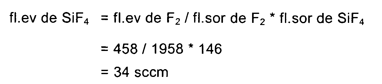
Comme le flux de F2 en sortie de la chambre de procédés 1 doit être
égal à 1958 sccm, et que le flux de F2 recirculant vaut 1500 sccm, le flux de F2
pompé par le pompage principal et évacué vaut 458 sccm.Since the flow of F 2 at the outlet of the
On fait ensuite l'hypothèse que le pompage principal évacue les gaz indépendamment de leur nature. Les proportions des gaz à l'entrée du pompage principal seront donc les mêmes que celles en sortie de la chambre de procédés. Et ces proportions de gaz correspondent aux proportions des flux.It is then assumed that the main pumping evacuates the gases regardless of their nature. Proportions of gases at the pumping inlet the main ones will be the same as those at the output of the process chamber. And these proportions of gases correspond to the proportions of the flows.
On a donc la relation suivante pour l'évacuation (1), valable pour les
quatre espèces N2, O2, F2 et SiF4 :
on note
we notice
Et il en découle que
Connaissant fl.ev de SiF4 et fl.sor de SiF4, on en déduit : flux piégé de
SiF4 = 112 sccm
Or la pompe évacue ce qui tend à faire augmenter la pression dans le
système, d'où
fl.ev total = bilan des réactions du NF3 injecté + bilan des réactions du F2 recyclé -
flux piégéKnowing fl.ev of SiF 4 and fl.sor of SiF 4 , we deduce: trapped flux of SiF 4 = 112 sccm
But the pump evacuates what tends to increase the pressure in the system, hence
total fl.ev = balance of injected NF 3 reactions + reaction balance of recycled F 2 - trapped flux
Bilan des réactions du NF3 injecté (500 sccm):
250 sccm de N2
250 sccm of N 2
Le bilan vaut 1000 sccm de gaz en plus.The balance is worth 1000 sccm more gas.
+ bilan des réactions du F2 recyclé (1500 sccm):
Le bilan est nul en terme de quantité de gaz.
- flux piégé (112 sccm)The balance is zero in terms of quantity of gas.
- trapped flux (112 sccm)
D'où fl.ev total = 1000 - 112 = 888 sccmWhere fl.ev total = 1000 - 112 = 888 sccm
On cherche ensuite à déterminer les flux de O2 et de N2.We then try to determine the flow of O 2 and N 2 .
On a pour O2 les deux relations suivantes :
On a pour N2 les deux relations suivantes :
On en déduit fl.ev de O2 et fl.ev de N2, puis avec la relation (1) viennent fl.sor de N2 et fl.sor de O2, et enfin fl.rec de N2 et fl.rec de O2 en écrivant dans les relations (2) et (3) les valeurs calculées de fl.sor de N2 et fl.sor de O2.We deduce fl.ev of O 2 and fl.ev of N 2 , then with relation (1) come fl.sor of N 2 and Fl.sor of O 2 , and finally fl.rec of N 2 and fl. rec O 2 by writing in relations (2) and (3) the calculated fl.sor N 2 and O 2 fl.sor.
Ce modèle repose sur l'hypothèse que même si le flux total passant dans la chambre est différent du flux habituel, la réactivité des atomes de fluor vis à vis du silicium restera la même (13%).This model is based on the assumption that even if the total flow in the chamber is different from the usual flow, the reactivity of fluorine atoms screws to silicon screw will remain the same (13%).
Exemple : en appliquant ces dernières relations, on obtient tous les flux
(en sccm)
Le flux de recirculation est de 2800 sccm si on décide d'économiser les deux tiers de l'injection standard de NF3.The recirculation flow is 2800 sccm if we decide to save two thirds of the standard NF 3 injection.
Les équations ci-dessus sont utilisables pour déterminer chacun des
points de la courbe de variation nécessaire du flux de recirculation pour obtenir le
flux désiré de produits de nettoyage dans la chambre de procédés 1.The equations above can be used to determine each of the
points of the required variation curve of the recirculation flow to get the
desired flow of cleaning products in the
La présente invention n'est pas limitée aux modes de réalisation qui ont été explicitement décrits, mais elle en inclut les diverses variantes et généralisations qui sont à la portée de l'homme du métier.The present invention is not limited to the embodiments which have have been explicitly described, but it includes the various variants and generalizations that are within the reach of those skilled in the art.
Claims (17)
Applications Claiming Priority (2)
| Application Number | Priority Date | Filing Date | Title |
|---|---|---|---|
| FR0314378 | 2003-12-09 | ||
| FR0314378A FR2863404B1 (en) | 2003-12-09 | 2003-12-09 | DEVICE FOR GENERATING AND CONTROLLING FLOW OF CLEANING AGENTS IN A CHAMBER OF PROCESSES |
Publications (1)
| Publication Number | Publication Date |
|---|---|
| EP1541709A1 true EP1541709A1 (en) | 2005-06-15 |
Family
ID=34508616
Family Applications (1)
| Application Number | Title | Priority Date | Filing Date |
|---|---|---|---|
| EP04292907A Withdrawn EP1541709A1 (en) | 2003-12-09 | 2004-12-06 | Arrangement for the control of the flow rate of cleaning agents in a recirculation dispositive |
Country Status (4)
| Country | Link |
|---|---|
| US (1) | US20050229955A1 (en) |
| EP (1) | EP1541709A1 (en) |
| JP (1) | JP2005197667A (en) |
| FR (1) | FR2863404B1 (en) |
Families Citing this family (2)
| Publication number | Priority date | Publication date | Assignee | Title |
|---|---|---|---|---|
| US9753463B2 (en) * | 2014-09-12 | 2017-09-05 | Applied Materials, Inc. | Increasing the gas efficiency for an electrostatic chuck |
| JP6531487B2 (en) * | 2015-05-22 | 2019-06-19 | 東京エレクトロン株式会社 | Deposition apparatus, deposition method, and storage medium |
Citations (8)
| Publication number | Priority date | Publication date | Assignee | Title |
|---|---|---|---|---|
| JPH09251981A (en) * | 1996-03-14 | 1997-09-22 | Toshiba Corp | Semiconductor manufacturing equipment |
| EP1164628A2 (en) * | 2000-06-13 | 2001-12-19 | Applied Materials, Inc. | Processing system and method |
| JP2002033315A (en) * | 2000-07-18 | 2002-01-31 | Seiko Epson Corp | Method and device for cleaning film-forming apparatus |
| US20020034880A1 (en) * | 2000-09-21 | 2002-03-21 | Kabushiki Kaisha Toshiba | Semiconductor processing apparatus and method for manufacturing a semiconductor device |
| EP1243667A2 (en) * | 2001-03-22 | 2002-09-25 | Ebara Corporation | Gas recirculation flow control method and apparatus for use in vacuum system for semiconductor manufacture |
| JP2003017416A (en) * | 2001-07-03 | 2003-01-17 | Tokyo Electron Ltd | Processing system and method |
| US20030036272A1 (en) * | 2000-06-13 | 2003-02-20 | Applied Materials, Inc. | Semiconductor device fabrication chamber cleaning method and apparatus with recirculation of cleaning gas |
| EP1371750A1 (en) * | 2002-06-10 | 2003-12-17 | The Boc Group, Inc. | Method of recycling fluorine using an adsorption purification process |
Family Cites Families (9)
| Publication number | Priority date | Publication date | Assignee | Title |
|---|---|---|---|---|
| US3225825A (en) * | 1962-07-13 | 1965-12-28 | Martin Sweets Company Inc | Cold trap |
| US4792526A (en) * | 1982-12-21 | 1988-12-20 | Union Oil Company Of California | Method for collecting and analyzing hydrocarbons |
| US4679402A (en) * | 1986-08-11 | 1987-07-14 | Helix Technology Corporation | Cooling heat exchanger |
| JPH0451981A (en) * | 1990-06-19 | 1992-02-20 | San Denshi Kk | Automatic display device |
| US5812403A (en) * | 1996-11-13 | 1998-09-22 | Applied Materials, Inc. | Methods and apparatus for cleaning surfaces in a substrate processing system |
| US5944049A (en) * | 1997-07-15 | 1999-08-31 | Applied Materials, Inc. | Apparatus and method for regulating a pressure in a chamber |
| JP2000009037A (en) * | 1998-06-18 | 2000-01-11 | Fujitsu Ltd | Exhaust device and exhaust method |
| JP2000068212A (en) * | 1998-08-21 | 2000-03-03 | Ebara Corp | Semiconductor manufacturing method and apparatus having gas circulation mechanism |
| JP3891834B2 (en) * | 2001-12-04 | 2007-03-14 | 大陽日酸株式会社 | Gas supply method and apparatus |
-
2003
- 2003-12-09 FR FR0314378A patent/FR2863404B1/en not_active Expired - Fee Related
-
2004
- 2004-12-06 EP EP04292907A patent/EP1541709A1/en not_active Withdrawn
- 2004-12-07 US US11/004,882 patent/US20050229955A1/en not_active Abandoned
- 2004-12-07 JP JP2004353801A patent/JP2005197667A/en active Pending
Patent Citations (8)
| Publication number | Priority date | Publication date | Assignee | Title |
|---|---|---|---|---|
| JPH09251981A (en) * | 1996-03-14 | 1997-09-22 | Toshiba Corp | Semiconductor manufacturing equipment |
| EP1164628A2 (en) * | 2000-06-13 | 2001-12-19 | Applied Materials, Inc. | Processing system and method |
| US20030036272A1 (en) * | 2000-06-13 | 2003-02-20 | Applied Materials, Inc. | Semiconductor device fabrication chamber cleaning method and apparatus with recirculation of cleaning gas |
| JP2002033315A (en) * | 2000-07-18 | 2002-01-31 | Seiko Epson Corp | Method and device for cleaning film-forming apparatus |
| US20020034880A1 (en) * | 2000-09-21 | 2002-03-21 | Kabushiki Kaisha Toshiba | Semiconductor processing apparatus and method for manufacturing a semiconductor device |
| EP1243667A2 (en) * | 2001-03-22 | 2002-09-25 | Ebara Corporation | Gas recirculation flow control method and apparatus for use in vacuum system for semiconductor manufacture |
| JP2003017416A (en) * | 2001-07-03 | 2003-01-17 | Tokyo Electron Ltd | Processing system and method |
| EP1371750A1 (en) * | 2002-06-10 | 2003-12-17 | The Boc Group, Inc. | Method of recycling fluorine using an adsorption purification process |
Non-Patent Citations (3)
| Title |
|---|
| PATENT ABSTRACTS OF JAPAN vol. 1998, no. 01 30 January 1998 (1998-01-30) * |
| PATENT ABSTRACTS OF JAPAN vol. 2002, no. 05 3 May 2002 (2002-05-03) * |
| PATENT ABSTRACTS OF JAPAN vol. 2003, no. 05 12 May 2003 (2003-05-12) * |
Also Published As
| Publication number | Publication date |
|---|---|
| US20050229955A1 (en) | 2005-10-20 |
| FR2863404B1 (en) | 2006-04-21 |
| JP2005197667A (en) | 2005-07-21 |
| FR2863404A1 (en) | 2005-06-10 |
Similar Documents
| Publication | Publication Date | Title |
|---|---|---|
| EP1669609B1 (en) | Gas partial pressure control for process optimisation | |
| EP1043645B1 (en) | Pressure control system for a vacuum chamber, vacuum pumping unit provided with such a system | |
| TWI388729B (en) | Fore-line preconditioning for vacuum pumps | |
| EP2875240B1 (en) | Method and device for pumping of a process chamber | |
| EP1190285A1 (en) | Method and device for conditioning atmosphere in a process chamber | |
| US6216548B1 (en) | Method for sampling particles present in a processing chamber | |
| FR2549223A1 (en) | COUNTERCURRENT LEAK DETECTOR WITH COLD TRAP | |
| FR2705104A1 (en) | Method for increasing the coating speed, method for reducing the density of dust in a plasma discharge space, and plasma chamber. | |
| EP2042849B1 (en) | Device and method for detecting high-pressure leaks using tracer gas in a part to be tested | |
| FR2664367A1 (en) | DRYING OF BIOLOGICAL MATERIALS. | |
| EP3201469A1 (en) | Pumping system for generating a vacuum and method for pumping by means of this pumping system | |
| WO2006134289A1 (en) | Method for controlling the pressure in a process chamber | |
| EP3676589B1 (en) | Leak detector and leak detection method for leak-testing objects | |
| EP1541709A1 (en) | Arrangement for the control of the flow rate of cleaning agents in a recirculation dispositive | |
| FR2860841A3 (en) | IMPROVEMENTS IN THE EFFICIENCY OF A PUMPING SYSTEM | |
| FR3094762A1 (en) | Dry type vacuum pump and pumping installation | |
| JP2507518B2 (en) | Vacuum exhaust device | |
| FR2923946A1 (en) | EQUIPMENT FOR MANUFACTURING SEMICONDUCTORS, PUMPING DEVICE AND CORRESPONDING SUBSTRATE HOLDER | |
| FR2907219A1 (en) | Gas sampling device for use in gas analyzing system, has variable conductance valve placed on pipe such that downstream pressure of valve is regulated at chosen set point pressure and is independent of upstream pressure of valve | |
| WO2001081651A1 (en) | Method and system for pumping semiconductor equipment from transfer chambers | |
| WO2017089588A1 (en) | Method and facility for drying a vacuum chamber | |
| EP1538656A1 (en) | System for plasma treatment of gases in a vacuum pump | |
| JPH062143A (en) | Cleaning method of deposited film forming device | |
| Vane | Immobilization and removal of hydrocarbon contamination using the evactron de-contaminator | |
| FR2792083A1 (en) | Pressure regulation in semi-conductor fabrication chamber under vacuum and associated vacuum pump |
Legal Events
| Date | Code | Title | Description |
|---|---|---|---|
| PUAI | Public reference made under article 153(3) epc to a published international application that has entered the european phase |
Free format text: ORIGINAL CODE: 0009012 |
|
| AK | Designated contracting states |
Kind code of ref document: A1 Designated state(s): AT BE BG CH CY CZ DE DK EE ES FI FR GB GR HU IE IS IT LI LT LU MC NL PL PT RO SE SI SK TR |
|
| AX | Request for extension of the european patent |
Extension state: AL BA HR LV MK YU |
|
| 17P | Request for examination filed |
Effective date: 20051215 |
|
| AKX | Designation fees paid |
Designated state(s): AT BE BG CH CY CZ DE DK EE ES FI FR GB GR HU IE IS IT LI LT LU MC NL PL PT RO SE SI SK TR |
|
| RAP1 | Party data changed (applicant data changed or rights of an application transferred) |
Owner name: ALCATEL LUCENT |
|
| GRAP | Despatch of communication of intention to grant a patent |
Free format text: ORIGINAL CODE: EPIDOSNIGR1 |
|
| STAA | Information on the status of an ep patent application or granted ep patent |
Free format text: STATUS: THE APPLICATION IS DEEMED TO BE WITHDRAWN |
|
| 18D | Application deemed to be withdrawn |
Effective date: 20081107 |