EP1541404A2 - Device for accelerating or decelerating a motor vehicle - Google Patents
Device for accelerating or decelerating a motor vehicle Download PDFInfo
- Publication number
- EP1541404A2 EP1541404A2 EP04028827A EP04028827A EP1541404A2 EP 1541404 A2 EP1541404 A2 EP 1541404A2 EP 04028827 A EP04028827 A EP 04028827A EP 04028827 A EP04028827 A EP 04028827A EP 1541404 A2 EP1541404 A2 EP 1541404A2
- Authority
- EP
- European Patent Office
- Prior art keywords
- actuating
- motor vehicle
- footrest
- actuating elements
- actuators
- Prior art date
- Legal status (The legal status is an assumption and is not a legal conclusion. Google has not performed a legal analysis and makes no representation as to the accuracy of the status listed.)
- Granted
Links
Images

Classifications
-
- G—PHYSICS
- G05—CONTROLLING; REGULATING
- G05G—CONTROL DEVICES OR SYSTEMS INSOFAR AS CHARACTERISED BY MECHANICAL FEATURES ONLY
- G05G1/00—Controlling members, e.g. knobs or handles; Assemblies or arrangements thereof; Indicating position of controlling members
- G05G1/01—Arrangements of two or more controlling members with respect to one another
-
- B—PERFORMING OPERATIONS; TRANSPORTING
- B60—VEHICLES IN GENERAL
- B60K—ARRANGEMENT OR MOUNTING OF PROPULSION UNITS OR OF TRANSMISSIONS IN VEHICLES; ARRANGEMENT OR MOUNTING OF PLURAL DIVERSE PRIME-MOVERS IN VEHICLES; AUXILIARY DRIVES FOR VEHICLES; INSTRUMENTATION OR DASHBOARDS FOR VEHICLES; ARRANGEMENTS IN CONNECTION WITH COOLING, AIR INTAKE, GAS EXHAUST OR FUEL SUPPLY OF PROPULSION UNITS IN VEHICLES
- B60K26/00—Arrangements or mounting of propulsion unit control devices in vehicles
- B60K26/02—Arrangements or mounting of propulsion unit control devices in vehicles of initiating means or elements
-
- B—PERFORMING OPERATIONS; TRANSPORTING
- B60—VEHICLES IN GENERAL
- B60T—VEHICLE BRAKE CONTROL SYSTEMS OR PARTS THEREOF; BRAKE CONTROL SYSTEMS OR PARTS THEREOF, IN GENERAL; ARRANGEMENT OF BRAKING ELEMENTS ON VEHICLES IN GENERAL; PORTABLE DEVICES FOR PREVENTING UNWANTED MOVEMENT OF VEHICLES; VEHICLE MODIFICATIONS TO FACILITATE COOLING OF BRAKES
- B60T7/00—Brake-action initiating means
- B60T7/02—Brake-action initiating means for personal initiation
- B60T7/04—Brake-action initiating means for personal initiation foot actuated
- B60T7/042—Brake-action initiating means for personal initiation foot actuated by electrical means, e.g. using travel or force sensors
-
- G—PHYSICS
- G05—CONTROLLING; REGULATING
- G05G—CONTROL DEVICES OR SYSTEMS INSOFAR AS CHARACTERISED BY MECHANICAL FEATURES ONLY
- G05G1/00—Controlling members, e.g. knobs or handles; Assemblies or arrangements thereof; Indicating position of controlling members
- G05G1/58—Rests or guides for relevant parts of the operator's body
- G05G1/60—Foot rests or foot guides
Definitions
- Such a device has at least two actuators, wherein by means of one of these actuators acceleration brought about, kept the speed, or even when not in operation due to the drag torque of engine, transmission and drivetrain one Delay of the motor vehicle can be effected.
- Another one Actuating means is used to brake the motor vehicle when actuated.
- a third Actuator a coupling process between the engine and the Drive train or to disconnect the clutch.
- From DE 198 11 268 A1 is a foot-operated operating device for a Motor vehicle is known which has at least two actuating elements, arranged side by side on a floor panel of the motor vehicle are. Depending on the actuation of the actuators is generates a control signal, which on the one hand to influence the Motor torque and on the other to effect a deceleration of the Motor vehicle is used.
- a known from EP 1 139 195 A1 acceleration or Brake pedal device has two spaced apart Actuators on. Between these actuators is a Footrest provided. The actuators, as well as the footrest be from a vertical support element at a distance to Bottom plate of the motor vehicle held. Depending on the on the Actuators each acting force is either one Acceleration or deceleration of the motor vehicle effected.
- Object of the present invention is to provide a device of the input mentioned type to be designed such that these comfortable operation meets high safety requirements.
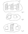
- the reference numeral 1 is a partial area of a Floor panel of a motor vehicle, on the at least a first and a second actuating element 2, 3 are arranged. These Actuators 2, 3 generate, at least almost without a way Output signal from one to the actuators 2, 3rd acting force depends.
- the first actuating element 2 can For example, serve to a drive torque for the motor vehicle produce. The motor vehicle can thus due to the first Actuator 2 acting force accelerates, it can Speed maintained, or due to drag torque, the from the engine, transmission and / or powertrain Braking torque can be generated. In common usage can This first actuator 2 thus an "accelerator" of a Motor vehicle correspond.
- the second actuating element 3 serves primarily in dependence from the force acting on the second actuating element 3, a To generate braking torque.
- a third actuator - as a clutch actuator - provide, through which a coupling between the drive means and a drive wheel made or this can be canceled.
- FIG. 1 shows that in particular between the Actuators 2, 3, a footrest 4 is provided, to which the right or even the left foot can be stored and which serves that an orientation in the footwell for a motor vehicle driver is possible.
- another footrest 5 left in addition to the second actuator 3 and a third footrest 6 right are provided in addition to the first actuating element 2.
- the surface by appropriate design serve. It is possible, for example, the Actuating surface of the actuators smooth and the foot rests 4,5,6, for example, form rough. Furthermore, the actuating surface could the actuators 2, 3 of a rubber coating and the Footrest 4, 5, 6 formed by a carpet.
- the actuating surface of the Actuators 2,3 and / or the surface of the footrest 4, 5, 6 in be arranged at different levels (Fig. 2).
- the surface of at least one of the foot rests 4, 5, 6 a greater distance from the floor panel 1 has as the actuating surface the first and / or the second actuating element 2, 3.
- Such Embodiment is apparent in particular from Figure 3. This results comfortable operation with high security against Confusion.
- the actuators 2, 3 can be in a position in which they are arranged in conventional vehicles. In the context of the invention, however, at least the second actuating element 3 can assume a position which is shown in dashed line. Here, the second actuating element 3 is then in a position in the region of the left-hand wheel arch - left-hand drive vehicle - for example where the clutch would be located in vehicles with a manual transmission. This relatively large distance between the actuators 2, 3 on the one hand leads to the risk of confusion is further reduced, on the other hand it is also possible that the vehicle can be operated with both the right and with the left foot.
- the position of the actuators 2, 3 can be fixed in the vehicle or it can also be variable, if, for example, the actuators 2, 3 along a guide adjustable and can be locked in a desired position.
- this circuitry is excluded that when actuated second actuator 3 in addition an engine torque is generated due to a force on the first actuator 2.
- the generation of a braking torque always takes precedence.
- the actuators can 2, 3 be executed with a "crackpot” function, that is, only at Exceeding a predetermined force, an output signal from the Actuators 2.3 provided.
- This "crackpot frog" Of course, function can also be effected electronically. Accordingly, it takes place only after exceeding a predetermined or predeterminable Signal height an evaluation of the output signals of the actuators 2,3, which can also be different.
Landscapes
- Engineering & Computer Science (AREA)
- Transportation (AREA)
- Mechanical Engineering (AREA)
- Physics & Mathematics (AREA)
- General Physics & Mathematics (AREA)
- Automation & Control Theory (AREA)
- Chemical & Material Sciences (AREA)
- Combustion & Propulsion (AREA)
- Regulating Braking Force (AREA)
- Passenger Equipment (AREA)
- Electric Propulsion And Braking For Vehicles (AREA)
Abstract
Description
Eine solche Vorrichtung weist wenigstens zwei Betätigungselemente auf, wobei mittels eines dieser Betätigungselemente eine Beschleunigung herbeigeführt, die Geschwindigkeit gehalten, oder auch bei Nichtbetätigung aufgrund der Schleppmomente von Motor, Getriebe und Antriebsstrang eine Verzögerung des Kraftfahrzeuges bewirkt werden kann. Ein weiteres Betätigungsmittel dient bei Betätigung zum Abbremsen des Kraftfahrzeuges. Ferner ist es bekannt, aufgrund der Betätigung eines dritten Betätigungselementes, einen Kuppelvorgang zwischen dem Motor und dem Antriebsstrang zu bewirken oder die Kupplung zu trennen.Such a device has at least two actuators, wherein by means of one of these actuators acceleration brought about, kept the speed, or even when not in operation due to the drag torque of engine, transmission and drivetrain one Delay of the motor vehicle can be effected. Another one Actuating means is used to brake the motor vehicle when actuated. Furthermore, it is known due to the actuation of a third Actuator, a coupling process between the engine and the Drive train or to disconnect the clutch.
Aus der DE 198 11 268 A1 ist eine fußbetätigte Bedienvorrichtung für ein Kraftfahrzeug bekannt, das zumindest zwei Betätigungselemente aufweist, die nebeneinander auf einem Bodenblech des Kraftfahrzeuges angeordnet sind. In Abhängigkeit vom Betätigungsweg der Betätigungselemente wird ein Steuersignal erzeugt, das zum einen zur Beeinflussung des Motormomentes und zum anderen zum Bewirken einer Abbremsung des Kraftfahrzeugs herangezogen wird.From DE 198 11 268 A1 is a foot-operated operating device for a Motor vehicle is known which has at least two actuating elements, arranged side by side on a floor panel of the motor vehicle are. Depending on the actuation of the actuators is generates a control signal, which on the one hand to influence the Motor torque and on the other to effect a deceleration of the Motor vehicle is used.
Eine aus der EP 1 139 195 A1 bekannte Beschleunigungs- oder
Bremspedaleinrichtung weist zwei im Abstand zueinander angeordnete
Betätigungselemente auf. Zwischen diesen Betätigungselementen ist eine
Fußablage vorgesehen. Die Betätigungselemente, sowie die Fußablage
werden von einem vertikalen Tragelement in einem Abstand zum
Bodenblech des Kraftfahrzeuges gehalten. In Abhängigkeit von der auf die
Betätigungselemente jeweils einwirkenden Kraft ist entweder eine
Beschleunigung oder eine Abbremsung des Kraftfahrzeuges bewirkbar.A known from
Aufgabe der vorliegenden Erfindung ist es, eine Vorrichtung der Eingangs genannten Art derart auszuführen, dass diese bei komfortabler Bedienung hohen Sicherheitsanforderungen gerecht wird.Object of the present invention is to provide a device of the input mentioned type to be designed such that these comfortable operation meets high safety requirements.
Die Aufgabe wird erfindungsgemäß durch den Gegenstand des
Patentanspruchs 1 gelöst.The object is achieved by the subject of
Weiterbildungen und vorteilhafte Ausgestaltungen der Erfindung ergeben sich aus der nachfolgenden Beschreibung eines Ausführungsbeispiels anhand der Zeichnungen in Verbindung mit den Unteransprüchen.Developments and advantageous embodiments of the invention result from the following description of an embodiment With reference to the drawings in conjunction with the dependent claims.
Es zeigt:
-
Figur 1 - Eine Vorrichtung zum Beschleunigen oder Verzögern eines Kraftfahrzeuges mit wenigstens zwei Betätigungselementen,
-
Figur 2 - eine Vorrichtung nach der
Figur 1 mit in unterschiedlichen Ebenen angeordneten Betätigungsflächen der Betätigungselemente, -
Figur 3 - eine Vorrichtung mit zwischen den Betätigungselementen angeordneter Fußablage und
-
Figur 4 - eine Vorrichtung mit relativ zueinander verstellbaren Betätigungselementen.
- FIG. 1
- A device for accelerating or decelerating a motor vehicle with at least two actuators,
- FIG. 2
- FIG. 1 shows a device according to FIG. 1 with actuating surfaces of the actuating elements arranged in different planes;
- FIG. 3
- a device with arranged between the actuators footrest and
- FIG. 4
- a device with relatively adjustable actuators.
In der nachfolgenden Beschreibung der Erfindung anhand der Figuren werden gleiche Elemente mit den gleichen Bezugszahlen versehen. In the following description of the invention with reference to FIGS the same elements are given the same reference numbers.
In den Figuren ist mit dem Bezugszeichen 1 ein Teilbereich eines
Bodenbleches eines Kraftfahrzeuges gekennzeichnet, auf dem zumindest
ein erstes und ein zweites Betätigungselement 2, 3 angeordnet sind. Diese
Betätigungselemente 2, 3 erzeugen, zumindest nahezu weglos ein
Ausgangssignal, das von einer auf die Betätigungselemente 2, 3
einwirkenden Kraft abhängt. Das erste Betätigungselement 2 kann
beispielsweise dazu dienen, ein Antriebsmoment für das Kraftfahrzeug zu
erzeugen. Das Kraftfahrzeug kann somit aufgrund der auf das erste
Betätigungselement 2 wirkenden Kraft beschleunigt, es kann die
Geschwindigkeit gehalten, oder auch aufgrund von Schleppmomenten, die
vom Motor, dem Getriebe und/oder vom Antriebsstrang ausgehen, ein
Bremsmoment erzeugt werden. Im allgemeinen Sprachgebrauch kann
dieses erste Betätigungselement 2 somit einem "Gaspedal" eines
Kraftfahrzeuges entsprechen.In the figures, the
Das zweite Betätigungselement 3 dient in erster Linie dazu, in Abhängigkeit
von der auf das zweite Betätigungselement 3 einwirkenden Kraft, ein
Bremsmoment zu erzeugen.The second actuating
Sollte das Kraftfahrzeug mit einem Schaltgetriebe ausgeführt sein, so wäre dann ein drittes Betätigungselement - als Kupplungsbetätigungselement - vorzusehen, durch das eine Kopplung zwischen der Antriebseinrichtung und einem Antriebsrad hergestellt oder diese aufgehoben werden kann.If the motor vehicle should be designed with a manual transmission, it would be then a third actuator - as a clutch actuator - provide, through which a coupling between the drive means and a drive wheel made or this can be canceled.
Durch die direkte Anordnung der Betätigungselemente auf dem Bodenblech ist auch die Verletzungsgefahr, die von einer üblichen Pedalarie bei einem Unfall aus geht, erheblich reduziert.Due to the direct arrangement of the actuators on the floor panel is also the risk of injury from a usual pedaling at a Accident goes out, considerably reduced.
Aus der Figur 1 geht hervor, dass insbesondere zwischen den
Betätigungselementen 2, 3 eine Fußablage 4 vorgesehen ist, auf die der
rechte oder auch der linke Fuß abgelegt werden kann und die dazu dient,
dass eine Orientierung im Fußraum für einen Kraftfahrzeugfahrer möglich ist.From Figure 1 shows that in particular between the
Es ist gezeigt, dass alternativ oder zusätzlich eine weitere Fußablage 5 links
neben dem zweiten Betätigungselement 3 und eine dritte Fußablage 6 rechts
neben dem ersten Betätigungselement 2 vorgesehen sind. Zur
Unterscheidung, ob sich der Fuß auf einem Betätigungselement 2, 3 oder auf
einer Fußablage 4, 5, 6 befindet, kann beispielsweise die Oberfläche durch
entsprechende Ausgestaltung dienen. Es ist zum Beispiel möglich, die
Betätigungsfläche der Betätigungselemente glatt und die der Fußablagen
4,5,6 beispielsweise rau auszubilden. Ferner könnte die Betätigungsfläche
der Betätigungselemente 2, 3 von einem Gummibelag und die der
Fußablage 4, 5, 6 von einem Teppich gebildet sein.It is shown that alternatively or additionally, another
Zur weiteren Unterscheidung können die Betätigungsfläche der
Betätigungselemente 2,3 und/oder die Oberfläche der Fußablage 4, 5, 6 in
unterschiedlichen Ebenen angeordnet sein (Fig. 2). Als besonders vorteilhaft
erscheint es, wenn die Oberfläche zumindest einer der Fußablagen 4, 5, 6
einen größeren Abstand zum Bodenblech 1 hat als die Betätigungsfläche
des ersten und/oder des zweiten Betätigungselementes 2, 3. Eine solche
Ausgestaltung geht insbesondere aus der Figur 3 hervor. Hierdurch ergibt
sich eine komfortable Bedienbarkeit bei hoher Sicherheit gegen
Verwechslung.For further distinction, the actuating surface of the
In der Figur 4 ist dargestellt, dass sich die Betätigungselemente 2, 3 sich in
einer Positionen befinden können, in der sie auch in herkömmlichen
Fahrzeugen angeordnet sind. Im Rahmen der Erfindung kann aber auch
zumindest das zweite Betätigungselement 3 eine Position einnehmen, die in
gestrichelter Linie dargestellt ist. Hier befindet sich das zweite
Betätigungselement 3 dann in einer Position im Bereich des linken
Radhauses - Linkslenker Fahrzeug - , beispielsweise da, wo sich bei
Fahrzeugen mit Schaltgetriebe die Kupplung befinden würde. Diese relativ
große Entfernung zwischen den Betätigungselementen 2, 3 führt zum einen
dazu, dass die Verwechslungsgefahr weiter reduziert wird, zum anderen ist
es so auch möglich, dass das Fahrzeug sowohl mit dem rechten, als auch
mit dem linken Fuß bedient werden kann. Die Position der
Betätigungselemente 2, 3 kann im Fahrzeug fest vorgegeben oder sie kann
auch variabel sein, wenn hierzu beispielsweise die Betätigungselemente 2, 3
entlang einer Führung verstellbar und in einer gewünschten Position
arretierbar sind.
Selbstverständlich ist hierbei schaltungstechnisch ausgeschlossen, dass bei
betätigtem zweiten Betätigungselement 3 zusätzlich ein Motormoment
aufgrund einer Krafteinwirkung auf das erste Betätigungselement 2 erzeugt
wird. Hier hat immer die Erzeugung eines Bremsmomentes Vorrang.In the figure 4 it is shown that the
Of course, this circuitry is excluded that when actuated
Um die Orientierung weiter zu erleichtern, können die Betätigungselemente
2, 3 mit einer "Knackfrosch" Funktion ausgeführt sein, dass heißt, erst beim
Überschreiten einer vorbestimmten Kraft wird ein Ausgangssignal von den
Betätigungselementen 2,3 zur Verfügung gestellt. Diese "Knackfrosch"
Funktion kann natürlich auch elektronisch bewirkt werden. Demnach erfolgt
erst nach Überschreiten einer vorbestimmten oder vorbestimmbaren
Signalhöhe eine Auswertung der Ausgangssignale der Betätigungselemente
2,3, die auch unterschiedlich sein kann.To further facilitate orientation, the actuators can
2, 3 be executed with a "crackpot" function, that is, only at
Exceeding a predetermined force, an output signal from the
Actuators 2.3 provided. This "crackpot frog"
Of course, function can also be effected electronically. Accordingly, it takes place
only after exceeding a predetermined or predeterminable
Signal height an evaluation of the output signals of the
Im Rahmen der Erfindung ist es natürlich auch möglich, dass das zweite
Betätigungselement 3 die Funktion des ersten Betätigungselementes 2 und
das erste Betätigungselement 2 die Funktion des zweiten
Betätigungselementes 3 erfüllt.In the context of the invention, it is of course also possible that the
Claims (11)
mit wenigstens zwei Betätigungselementen 2, 3, die jeweils aufgrund einer einwirkenden Kraft, zumindest nahezu weglos, jeweils ein Ausgangssignal erzeugen, welches zum Beschleunigen, Verzögern und/oder Geschwindigkeit halten herangezogen werden kann,
wobei die Betätigungselemente (2, 3) im Fußraum des Kraftfahrzeuges und in einem Abstand zueinander auf dem Bodenblech (1) angeordnet sind und
mit einer Fußablage (4,5,6) die zumindest einem Betätigungselement (2, 3) zugeordnet ist.Device for accelerating or decelerating a motor vehicle,
with at least two actuating elements 2, 3, which in each case generate an output signal which can be used for accelerating, decelerating and / or speed, in each case due to an acting force, at least almost without a track,
wherein the actuating elements (2, 3) in the footwell of the motor vehicle and at a distance from each other on the floor panel (1) are arranged and
with a footrest (4,5,6) which is associated with at least one actuating element (2, 3).
wobei die Betätigungsflächen der Betätigungselemente (2, 3) in unterschiedlichen Ebenen angeordnet sind.Device according to claim 1,
wherein the actuating surfaces of the actuating elements (2, 3) are arranged in different planes.
wobei die Fußablage (4,5,6) neben dem Betätigungselement (2) zum Erzeugen einer Beschleunigung des Kraftfahrzeugs angeordnet ist.Apparatus according to claim 1 or claim 2,
wherein the footrest (4,5,6) is arranged adjacent to the actuating element (2) for generating an acceleration of the motor vehicle.
wobei die Fußablage (4) zwischen den Betätigungselementen (2, 3) angeordnet ist.Device according to one of claims 1 to 3,
wherein the footrest (4) between the actuating elements (2, 3) is arranged.
wobei die Oberfläche der Fußablage (4,5,6) in einer zu den Betätigungsflächen der Betätigungselemente (2, 3) unterschiedlichen Ebene angeordnet ist.Device according to one of claims 1 to 4,
wherein the surface of the footrest (4,5,6) is arranged in a plane different from the actuating surfaces of the actuating elements (2, 3).
wobei die Oberfläche der Fußablage (4,5,6) einen größeren Abstand zum Bodenblech (1) hat, als die Betätigungsflächen der Betätigungselemente (2, 3).Device according to one of claims 1 to 5,
wherein the surface of the footrest (4,5,6) has a greater distance from the floor panel (1), as the actuating surfaces of the actuating elements (2, 3).
wobei die Betätigungselemente (2, 3) erst nach Überwindung einer vorbestimmten Kraft ein Signal erzeugen.Device according to one of claims 1 to 6,
wherein the actuating elements (2, 3) generate a signal only after overcoming a predetermined force.
wobei das Signal der Betätigungselemente (2, 3) erst ab einer vorbestimmten Signalhöhe zur Auswertung herangezogen wird.Device according to one of claims 1 to 7,
wherein the signal of the actuating elements (2, 3) is used only from a predetermined signal level for evaluation.
wobei der Abstand der Betätigungselemente 2, 3 zueinander veränderbar ist.Device according to one of claims 1 to 8,
wherein the distance of the actuating elements 2, 3 is mutually variable.
wobei ein erstes Betätigungselement (2) rechts und das zweite Betätigungselement (3) links in einem dem Kraftfahrzeugfahrer zugeordneten Fußraum des Kraftfahrzeugs angeordnet sind.Device according to one of claims 1 to 9,
wherein a first actuating element (2) on the right and the second actuating element (3) are arranged on the left in a foot space of the motor vehicle assigned to the motor vehicle driver.
wobei die Signale der Betätigungselemente (2,3) eine Anlage zum Bewirken einer Beschleunigung bzw. einer Anlage zum Bewirken einer Verzögerung zugeführt werden.Device according to one of claims 1 to 10,
wherein the signals of the actuators (2, 3) are supplied to a system for effecting an acceleration to effect deceleration.
Applications Claiming Priority (2)
| Application Number | Priority Date | Filing Date | Title |
|---|---|---|---|
| DE2003158227 DE10358227A1 (en) | 2003-12-12 | 2003-12-12 | Device for accelerating or decelerating a motor vehicle |
| DE10358227 | 2003-12-12 |
Publications (3)
| Publication Number | Publication Date |
|---|---|
| EP1541404A2 true EP1541404A2 (en) | 2005-06-15 |
| EP1541404A3 EP1541404A3 (en) | 2006-01-18 |
| EP1541404B1 EP1541404B1 (en) | 2008-04-30 |
Family
ID=34485348
Family Applications (1)
| Application Number | Title | Priority Date | Filing Date |
|---|---|---|---|
| EP20040028827 Not-in-force EP1541404B1 (en) | 2003-12-12 | 2004-12-06 | Device for accelerating or decelerating a motor vehicle |
Country Status (2)
| Country | Link |
|---|---|
| EP (1) | EP1541404B1 (en) |
| DE (2) | DE10358227A1 (en) |
Cited By (3)
| Publication number | Priority date | Publication date | Assignee | Title |
|---|---|---|---|---|
| DE102017117154A1 (en) * | 2017-07-28 | 2019-01-31 | Dr. Ing. H.C. F. Porsche Aktiengesellschaft | motor vehicle |
| WO2020142804A1 (en) * | 2019-01-08 | 2020-07-16 | Applied Electric Vehicles Pty Ltd | Foot actuated vehicle control surfaces, operation and control strategy |
| EP3712035A3 (en) * | 2019-03-20 | 2021-01-27 | Volvo Car Corporation | Vehicle having multiple driving positions |
Families Citing this family (1)
| Publication number | Priority date | Publication date | Assignee | Title |
|---|---|---|---|---|
| DE102011018580A1 (en) | 2011-04-26 | 2012-10-31 | Audi Ag | Karftfahrzeug comprising a driver assistance system |
Citations (2)
| Publication number | Priority date | Publication date | Assignee | Title |
|---|---|---|---|---|
| DE19811268A1 (en) | 1998-03-11 | 1999-09-16 | Helke Lob | Foot-operated operating device for controlling automobile acceleration or braking |
| EP1139195A1 (en) | 2000-03-28 | 2001-10-04 | FIAT AUTO S.p.A. | An accelerator and brake pedal device for a motor vehicle |
Family Cites Families (4)
| Publication number | Priority date | Publication date | Assignee | Title |
|---|---|---|---|---|
| US2167959A (en) * | 1938-08-29 | 1939-08-01 | Pomernacki Valerius | Automobile driver's instant foot control |
| DE19915240A1 (en) * | 1999-04-03 | 2000-10-05 | Volkswagen Ag | Safety device for motor vehicle has flexurally stiff support acting on footrest with lower end rigidly attached to footwell boundary wall and upper end acting on footrest beneath joint |
| WO2001025869A1 (en) * | 1999-10-07 | 2001-04-12 | Delphi Technologies, Inc. | Adjustable toepan assembly |
| DE10239913A1 (en) * | 2002-08-30 | 2004-03-18 | Audi Ag | Actuating means for influencing a system for braking, coupling or driving a motor vehicle |
-
2003
- 2003-12-12 DE DE2003158227 patent/DE10358227A1/en not_active Withdrawn
-
2004
- 2004-12-06 EP EP20040028827 patent/EP1541404B1/en not_active Not-in-force
- 2004-12-06 DE DE200450006990 patent/DE502004006990D1/en active Active
Patent Citations (2)
| Publication number | Priority date | Publication date | Assignee | Title |
|---|---|---|---|---|
| DE19811268A1 (en) | 1998-03-11 | 1999-09-16 | Helke Lob | Foot-operated operating device for controlling automobile acceleration or braking |
| EP1139195A1 (en) | 2000-03-28 | 2001-10-04 | FIAT AUTO S.p.A. | An accelerator and brake pedal device for a motor vehicle |
Cited By (5)
| Publication number | Priority date | Publication date | Assignee | Title |
|---|---|---|---|---|
| DE102017117154A1 (en) * | 2017-07-28 | 2019-01-31 | Dr. Ing. H.C. F. Porsche Aktiengesellschaft | motor vehicle |
| WO2020142804A1 (en) * | 2019-01-08 | 2020-07-16 | Applied Electric Vehicles Pty Ltd | Foot actuated vehicle control surfaces, operation and control strategy |
| EP3712035A3 (en) * | 2019-03-20 | 2021-01-27 | Volvo Car Corporation | Vehicle having multiple driving positions |
| US11292504B2 (en) | 2019-03-20 | 2022-04-05 | Volvo Car Corporation | Vehicle having multiple driving positions |
| US11801884B2 (en) | 2019-03-20 | 2023-10-31 | Volvo Car Corporation | Vehicle having multiple driving positions |
Also Published As
| Publication number | Publication date |
|---|---|
| DE502004006990D1 (en) | 2008-06-12 |
| EP1541404B1 (en) | 2008-04-30 |
| EP1541404A3 (en) | 2006-01-18 |
| DE10358227A1 (en) | 2005-07-14 |
Similar Documents
| Publication | Publication Date | Title |
|---|---|---|
| DE10315253B4 (en) | Vehicle accelerator pedal assembly | |
| DE102008003063B4 (en) | Automatic braking system | |
| DE102015217975B4 (en) | Method for disengaging a parking lock of a dual clutch transmission of a motor vehicle | |
| WO2011131320A1 (en) | Device for operating a drive unit of a motor vehicle | |
| DE112010005663T5 (en) | Driving Assistance System | |
| DE102007015889A1 (en) | Brake control system for motor vehicles | |
| DE102013106316A1 (en) | Auxiliary control for vehicle | |
| DE102008020842A1 (en) | Motor vehicle has control device and unit coupled with control device for switching between two operating modes of drive unit, where control device is coupled with brake pedal | |
| WO2020048695A1 (en) | Method for operating a motor vehicle, control unit, and motor vehicle | |
| EP2560845B1 (en) | Method for operating drive control units in a motor vehicle, and motor vehicle | |
| DE102009021662A1 (en) | Method for operating vehicle, involves recuperative braking of vehicle by brake system in lower area of adjustment travel of accelerator pedal, where drive unit is controlled in upper area of adjustment travel of accelerator pedal | |
| EP1541404A2 (en) | Device for accelerating or decelerating a motor vehicle | |
| DE102010042895A1 (en) | Adjustment device for power control of an internal combustion engine and method for power control of the internal combustion engine | |
| DE102011077354A1 (en) | Motor car, has brake piston arranged in displacement direction for providing alternative braking force generating facilities to change braking characteristics of wheel brakes based on driving condition of car | |
| DE102019215260B3 (en) | Method for deactivating a parking lock mechanism of a hybrid drive train for a motor vehicle | |
| DE102010011294A1 (en) | Driver assistance system for transmission of haptic signal over freewheeling path to driver of motor vehicle, has device producing haptic signal and arranged in vehicle seat of motor vehicle | |
| DE102010061438A1 (en) | Brake system e.g. electro-hydraulic friction brake system, for e.g. electric car, has brake control device axle-individually and/or wheel-individually distributing braking force, which corresponds to position of brake pedal | |
| EP1233894B1 (en) | Automotive braking method and device for carrying out said method | |
| DE10360784B4 (en) | Device for disengaging and engaging the clutch of a motor vehicle | |
| DE102017004048A1 (en) | Control of a manual transmission | |
| DE102009045852A1 (en) | Method for generating braking torque in all-wheel vehicle, involves arranging torque transmission element between drive motor and wheels of vehicle, where driving condition- or characteristic in vehicle lies within defined value range | |
| DE10052816A1 (en) | Device for conducting vehicle braking independently of brake pedal actuation drives brake actuators according to regulation of deceleration of vehicle in independent braking situation | |
| DE102016212089A1 (en) | Method and device for operating a motor vehicle, motor vehicle | |
| DE102009030345B4 (en) | Speed control in a motor vehicle with a limiting function | |
| DE102014012604A1 (en) | Device for actuating the service brake of a motor vehicle |
Legal Events
| Date | Code | Title | Description |
|---|---|---|---|
| PUAI | Public reference made under article 153(3) epc to a published international application that has entered the european phase |
Free format text: ORIGINAL CODE: 0009012 |
|
| AK | Designated contracting states |
Kind code of ref document: A2 Designated state(s): AT BE BG CH CY CZ DE DK EE ES FI FR GB GR HU IE IS IT LI LT LU MC NL PL PT RO SE SI SK TR |
|
| AX | Request for extension of the european patent |
Extension state: AL BA HR LV MK YU |
|
| PUAL | Search report despatched |
Free format text: ORIGINAL CODE: 0009013 |
|
| AK | Designated contracting states |
Kind code of ref document: A3 Designated state(s): AT BE BG CH CY CZ DE DK EE ES FI FR GB GR HU IE IS IT LI LT LU MC NL PL PT RO SE SI SK TR |
|
| AX | Request for extension of the european patent |
Extension state: AL BA HR LV MK YU |
|
| RIC1 | Information provided on ipc code assigned before grant |
Ipc: B60K 26/02 20060101AFI20050324BHEP Ipc: G05G 1/18 20060101ALI20051201BHEP |
|
| 17P | Request for examination filed |
Effective date: 20060301 |
|
| AKX | Designation fees paid |
Designated state(s): DE FR GB IT |
|
| 17Q | First examination report despatched |
Effective date: 20060524 |
|
| GRAP | Despatch of communication of intention to grant a patent |
Free format text: ORIGINAL CODE: EPIDOSNIGR1 |
|
| GRAC | Information related to communication of intention to grant a patent modified |
Free format text: ORIGINAL CODE: EPIDOSCIGR1 |
|
| GRAS | Grant fee paid |
Free format text: ORIGINAL CODE: EPIDOSNIGR3 |
|
| GRAA | (expected) grant |
Free format text: ORIGINAL CODE: 0009210 |
|
| AK | Designated contracting states |
Kind code of ref document: B1 Designated state(s): DE FR GB IT |
|
| REG | Reference to a national code |
Ref country code: GB Ref legal event code: FG4D Free format text: NOT ENGLISH |
|
| RIC1 | Information provided on ipc code assigned before grant |
Ipc: B60K 26/02 20060101AFI20080326BHEP Ipc: G05G 1/14 20080401ALI20080326BHEP |
|
| REF | Corresponds to: |
Ref document number: 502004006990 Country of ref document: DE Date of ref document: 20080612 Kind code of ref document: P |
|
| ET | Fr: translation filed | ||
| PLBE | No opposition filed within time limit |
Free format text: ORIGINAL CODE: 0009261 |
|
| STAA | Information on the status of an ep patent application or granted ep patent |
Free format text: STATUS: NO OPPOSITION FILED WITHIN TIME LIMIT |
|
| 26N | No opposition filed |
Effective date: 20090202 |
|
| REG | Reference to a national code |
Ref country code: DE Ref legal event code: R084 Ref document number: 502004006990 Country of ref document: DE Effective date: 20121001 |
|
| REG | Reference to a national code |
Ref country code: FR Ref legal event code: PLFP Year of fee payment: 12 |
|
| PGFP | Annual fee paid to national office [announced via postgrant information from national office to epo] |
Ref country code: GB Payment date: 20151221 Year of fee payment: 12 |
|
| PGFP | Annual fee paid to national office [announced via postgrant information from national office to epo] |
Ref country code: FR Payment date: 20151221 Year of fee payment: 12 |
|
| PGFP | Annual fee paid to national office [announced via postgrant information from national office to epo] |
Ref country code: DE Payment date: 20151231 Year of fee payment: 12 Ref country code: IT Payment date: 20151230 Year of fee payment: 12 |
|
| REG | Reference to a national code |
Ref country code: DE Ref legal event code: R119 Ref document number: 502004006990 Country of ref document: DE |
|
| GBPC | Gb: european patent ceased through non-payment of renewal fee |
Effective date: 20161206 |
|
| REG | Reference to a national code |
Ref country code: FR Ref legal event code: ST Effective date: 20170831 |
|
| PG25 | Lapsed in a contracting state [announced via postgrant information from national office to epo] |
Ref country code: FR Free format text: LAPSE BECAUSE OF NON-PAYMENT OF DUE FEES Effective date: 20170102 Ref country code: IT Free format text: LAPSE BECAUSE OF NON-PAYMENT OF DUE FEES Effective date: 20161206 |
|
| PG25 | Lapsed in a contracting state [announced via postgrant information from national office to epo] |
Ref country code: DE Free format text: LAPSE BECAUSE OF NON-PAYMENT OF DUE FEES Effective date: 20170701 Ref country code: GB Free format text: LAPSE BECAUSE OF NON-PAYMENT OF DUE FEES Effective date: 20161206 |