EP1541386A2 - Kraftfahrzeug-Luftfeder - Google Patents
Kraftfahrzeug-Luftfeder Download PDFInfo
- Publication number
- EP1541386A2 EP1541386A2 EP04029448A EP04029448A EP1541386A2 EP 1541386 A2 EP1541386 A2 EP 1541386A2 EP 04029448 A EP04029448 A EP 04029448A EP 04029448 A EP04029448 A EP 04029448A EP 1541386 A2 EP1541386 A2 EP 1541386A2
- Authority
- EP
- European Patent Office
- Prior art keywords
- rolling
- wall
- sensor element
- air spring
- rolling piston
- Prior art date
- Legal status (The legal status is an assumption and is not a legal conclusion. Google has not performed a legal analysis and makes no representation as to the accuracy of the status listed.)
- Granted
Links
- 238000005096 rolling process Methods 0.000 claims abstract description 98
- 229910000831 Steel Inorganic materials 0.000 claims abstract description 6
- 239000010959 steel Substances 0.000 claims abstract description 6
- XAGFODPZIPBFFR-UHFFFAOYSA-N aluminium Chemical compound [Al] XAGFODPZIPBFFR-UHFFFAOYSA-N 0.000 claims abstract description 5
- 229910052782 aluminium Inorganic materials 0.000 claims abstract description 5
- 230000001419 dependent effect Effects 0.000 claims abstract description 5
- 239000000463 material Substances 0.000 claims abstract description 5
- 238000007654 immersion Methods 0.000 claims description 16
- 238000001746 injection moulding Methods 0.000 claims description 10
- 238000002347 injection Methods 0.000 abstract description 3
- 239000007924 injection Substances 0.000 abstract description 3
- 238000010276 construction Methods 0.000 abstract 1
- 230000001133 acceleration Effects 0.000 description 2
- 239000000853 adhesive Substances 0.000 description 2
- 230000001070 adhesive effect Effects 0.000 description 2
- 238000009826 distribution Methods 0.000 description 2
- 239000013536 elastomeric material Substances 0.000 description 2
- 230000010354 integration Effects 0.000 description 2
- 239000011248 coating agent Substances 0.000 description 1
- 238000000576 coating method Methods 0.000 description 1
- 230000001934 delay Effects 0.000 description 1
- 238000001514 detection method Methods 0.000 description 1
- 230000000694 effects Effects 0.000 description 1
- 238000012423 maintenance Methods 0.000 description 1
- 238000004519 manufacturing process Methods 0.000 description 1
- 238000005259 measurement Methods 0.000 description 1
- 230000002093 peripheral effect Effects 0.000 description 1
- 238000002360 preparation method Methods 0.000 description 1
- 239000011435 rock Substances 0.000 description 1
- 230000035939 shock Effects 0.000 description 1
- 239000004575 stone Substances 0.000 description 1
- 239000000725 suspension Substances 0.000 description 1
Images




Classifications
-
- B—PERFORMING OPERATIONS; TRANSPORTING
- B60—VEHICLES IN GENERAL
- B60G—VEHICLE SUSPENSION ARRANGEMENTS
- B60G11/00—Resilient suspensions characterised by arrangement, location or kind of springs
- B60G11/26—Resilient suspensions characterised by arrangement, location or kind of springs having fluid springs only, e.g. hydropneumatic springs
- B60G11/28—Resilient suspensions characterised by arrangement, location or kind of springs having fluid springs only, e.g. hydropneumatic springs characterised by means specially adapted for attaching the spring to axle or sprung part of the vehicle
-
- B—PERFORMING OPERATIONS; TRANSPORTING
- B60—VEHICLES IN GENERAL
- B60G—VEHICLE SUSPENSION ARRANGEMENTS
- B60G11/00—Resilient suspensions characterised by arrangement, location or kind of springs
- B60G11/26—Resilient suspensions characterised by arrangement, location or kind of springs having fluid springs only, e.g. hydropneumatic springs
- B60G11/27—Resilient suspensions characterised by arrangement, location or kind of springs having fluid springs only, e.g. hydropneumatic springs wherein the fluid is a gas
-
- B—PERFORMING OPERATIONS; TRANSPORTING
- B60—VEHICLES IN GENERAL
- B60G—VEHICLE SUSPENSION ARRANGEMENTS
- B60G17/00—Resilient suspensions having means for adjusting the spring or vibration-damper characteristics, for regulating the distance between a supporting surface and a sprung part of vehicle or for locking suspension during use to meet varying vehicular or surface conditions, e.g. due to speed or load
- B60G17/015—Resilient suspensions having means for adjusting the spring or vibration-damper characteristics, for regulating the distance between a supporting surface and a sprung part of vehicle or for locking suspension during use to meet varying vehicular or surface conditions, e.g. due to speed or load the regulating means comprising electric or electronic elements
- B60G17/019—Resilient suspensions having means for adjusting the spring or vibration-damper characteristics, for regulating the distance between a supporting surface and a sprung part of vehicle or for locking suspension during use to meet varying vehicular or surface conditions, e.g. due to speed or load the regulating means comprising electric or electronic elements characterised by the type of sensor or the arrangement thereof
-
- B—PERFORMING OPERATIONS; TRANSPORTING
- B60—VEHICLES IN GENERAL
- B60G—VEHICLE SUSPENSION ARRANGEMENTS
- B60G17/00—Resilient suspensions having means for adjusting the spring or vibration-damper characteristics, for regulating the distance between a supporting surface and a sprung part of vehicle or for locking suspension during use to meet varying vehicular or surface conditions, e.g. due to speed or load
- B60G17/02—Spring characteristics, e.g. mechanical springs and mechanical adjusting means
- B60G17/04—Spring characteristics, e.g. mechanical springs and mechanical adjusting means fluid spring characteristics
- B60G17/052—Pneumatic spring characteristics
- B60G17/0521—Pneumatic spring characteristics the spring having a flexible wall
-
- B—PERFORMING OPERATIONS; TRANSPORTING
- B60—VEHICLES IN GENERAL
- B60G—VEHICLE SUSPENSION ARRANGEMENTS
- B60G2202/00—Indexing codes relating to the type of spring, damper or actuator
- B60G2202/10—Type of spring
- B60G2202/15—Fluid spring
- B60G2202/152—Pneumatic spring
-
- B—PERFORMING OPERATIONS; TRANSPORTING
- B60—VEHICLES IN GENERAL
- B60G—VEHICLE SUSPENSION ARRANGEMENTS
- B60G2204/00—Indexing codes related to suspensions per se or to auxiliary parts
- B60G2204/10—Mounting of suspension elements
- B60G2204/11—Mounting of sensors thereon
- B60G2204/111—Mounting of sensors thereon on pneumatic springs
-
- B—PERFORMING OPERATIONS; TRANSPORTING
- B60—VEHICLES IN GENERAL
- B60G—VEHICLE SUSPENSION ARRANGEMENTS
- B60G2204/00—Indexing codes related to suspensions per se or to auxiliary parts
- B60G2204/10—Mounting of suspension elements
- B60G2204/12—Mounting of springs or dampers
- B60G2204/126—Mounting of pneumatic springs
-
- B—PERFORMING OPERATIONS; TRANSPORTING
- B60—VEHICLES IN GENERAL
- B60G—VEHICLE SUSPENSION ARRANGEMENTS
- B60G2400/00—Indexing codes relating to detected, measured or calculated conditions or factors
- B60G2400/25—Stroke; Height; Displacement
- B60G2400/252—Stroke; Height; Displacement vertical
Definitions
- the invention relates to an air spring comprising a rolling piston and a Rolling bellows with a rolling fold, which can be unrolled on the wall of the rolling piston and at least one planar sensor element, which in the Rolling the rolling bellows is actuated and a height-dependent signal generated.
- Such an air spring is known from DE 101 30 507 A1.
- the previously known air spring is used to spring the axle of a motor vehicle used.
- the air spring consists of a rolling piston and a rolling bellows rolling on the rolling piston.
- a level control is necessary to a constant height of the vehicle.
- This level control can be via sensors carried out, which are integrated in the air spring. The sensors are on the Outside of the rolling piston arranged and determine the immersion depth of the Rolling bellows.
- the air spring is due to the arrangement in the region of the vehicle axle exposed to strong mechanical influences, such as stone chipping.
- the sensors are protected against the mechanical influences by embedding in an elastomeric coating protects the outer peripheral side of the Rolling piston is attached.
- the invention is based on the object, the previously known air spring such develop that it is inexpensive and easy to produce and better protected against external influences.
- the sensor element is integrated in the wall of the rolling piston or arranged on the cavity of the rolling piston facing side of the wall.
- the sensor element is protected against external influences, such as rockfall and moisture. Since the sensor element is integrated in the wall of the rolling piston or arranged on the side facing the cavity of the wall, the protection of the sensor element is carried out directly by the rolling piston, which is very robust against mechanical influences. A separately applied protection is not required and the sensor element is arranged wear and maintenance. Due to the integration in the rolling piston, the air spring on a simple structure with few components, whereby the number of manufacturing steps is reduced and the air spring is inexpensive to produce. The arrangement of the sensor element on the side facing the cavity of the rolling piston is particularly inexpensive. The arrangement of the sensor element within the wall provides a particularly good protection of the sensor element from damage.
- the rolling piston can be formed from a plastic injection molding. components made of plastic injection molding are easy and inexpensive to produce. Of the Material is inexpensive. There are complicated shapes possible. The Integration of the sensor element is in a rolling piston made of plastic injection molding especially easy.
- the Rolling piston be formed of aluminum. Aluminum is a lighter and more stable Material and can be processed by injection molding.
- the rolling piston can be made of steel. Rolling piston off Steel can be very thin-walled due to the strength of steel become.
- the sensor element can be encapsulated with the material of the wall. there the sensor element is placed in the mold during injection molding and is completely enclosed in plastic during injection molding. The Sensor element is thus protected from damage and wear and maintenance-free arranged in the rolling piston.
- the wall may be formed of two wall parts and the sensor element can be arranged between the two wall parts. That allows the Use of heat sensitive sensors that are not plastic injection molded can be integrated in the rolling piston.
- the object is also achieved by an air spring, in which the sensor element is arranged on the air inside facing side of the wall of the rolling bellows.
- the sensor element is thereby protected against mechanical damage, for example by falling rocks, and from moisture.
- the sensor element can be attached to the air-inside facing side of the rolling bellows with simple and inexpensive means, such as an adhesive bond.
- the arranged on the wall of the rolling bellows sensor element can as bend-sensitive film may be formed. With the bend-sensitive film, the Position of the rolling fold of the rolling bellows are determined, from which in turn the Immersion depth of the rolling piston is determined.
- each Sensor element detects the immersion depth of the rolling piston.
- the rolling piston By Accelerations, delays and the effect of uneven floors moves the rolling piston not only perpendicular to the rolling bellows, but leads also pitching and tumbling movements.
- the pitching and tumbling movement of the rolling piston be recorded.
- an integrated circuit consisting of the signals of individual sensor elements a mean immersion depth of the rolling piston determined. From the determined pitching and tumbling movements can with the integrated circuit, the mean immersion depth to be determined for the constant level control of a vehicle is necessary.
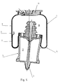
- Figure 1 shows an air spring 1 with a rolling piston 2, one with vertical Distance above the rolling piston 2 arranged air spring cover 11, a Rolling bellows 3 with a Abrollfalte 4 made of elastomeric material, the Air spring cover 11 and the rolling piston 2 connects and under Forming a volume-elastic air-space 8 on the wall 5 of the Abrollkolbens 2 is unrolled.
- the rolling piston 2 is made of plastic injection molding educated. Alternatively, the rolling piston also made of aluminum or steel be formed.
- On the cavity 7 of the rolling piston 2 side facing the wall 5 is a sensor element 6 for level detection of the air spring. 1 arranged.
- the sensor element 6 consists of a stretch-sensitive film and detects changes in tension of the wall 5 caused by the rolling motion of the bellows 3 on the wall 5 result.
- the sensor element 6 detects in particular the strain distribution of the rolling piston 2 in vertical Direction.
- the cavity 7 of the rolling piston 2 is connected to the air inside the eighth hydraulically connected, therefore prevails in the cavity 7, the same pressure as in Air Interior 8.
- the area of the wall 5 which is hidden by the rolling bellows 3 is, is tension-free due to the lack of pressure difference. In that area the wall 5 which is not covered by the rolling bellows 3 causes the Pressure difference between cavity 5 and environment 12 a voltage in the Wall 5 which is detected by the sensor element 6.
- the measure of Covering the rolling bellows 3 corresponds to the immersion depth H.
- a change of the altitude requires a specific change of the Strain maxima and the strain distribution in the vertical direction in the Wall of the rolling piston 2, which is detected by the sensor element. To For this purpose, it may be divided into one or more segments. Since that Sensor element 6 has a high gain, are also low voltage changes of the wall 5 detected. Based on the measured Immersion depth H is the height adjustment of the air spring. By a Height adjustment of all sprung with an air spring 1 axes is a Level control of a motor vehicle allows.
- FIG. 2 shows an air spring with a structure according to FIG Sensor element 6 is, however, in contrast to Figure 1 in the wall 5 of Rolling piston 2 integrated.
- the rolling piston 2 is made of plastic injection molding produced.
- the sensor element 6 is in the preparation of the rolling piston. 2 arranged in the injection mold and molded with plastic. This is the sensor element 6 completely enclosed with plastic and is opposite the environment 12 and the cavity 7 encapsulated.
- the contact of the Sensor element 6 to the wall 5 is at any time by the direct connection Maintenance-free and wear-free guaranteed.
- the sensor element 6 is as in the example of Figure 1 from a pressure-sensitive film and detected Voltage changes of the wall 5, by the rolling movement of the Rollbalgs 3 on the wall 5 result.
- Figure 3 shows an air spring according to Figure 2.
- the wall 5 is in this Embodiment constructed in two parts.
- the wall is through the two Wall parts 13, 14 formed.
- the sensor element 6 is between the two Wall parts 13, 14 arranged.
- FIG. 4 shows an air spring 1 consisting of a rolling piston 2 Plastic injection molding, a vertical distance above the rolling piston 2 arranged air spring cover 11, a rolling bellows 3 with a Abrollfalte 4 off elastomeric material, the air spring cover 11 and the rolling piston.
- 2 interconnects and forming a volume elastic Air inside 8 on the wall 5 of the rolling piston 2 is unrolled.
- the Sensor element 6 is on the air inside 8 facing side of the Wall 9 of the bellows 3 fixed by means of an adhesive bond.
- the Sensor element 6 is designed as a bend-sensitive film.
- the sensor element 6 detects the position of the Abrollfalte 4 on the rolling bellows 3 or thereof caused Strains of the rolling piston 2. This forms a measure of the immersion depth H of the rolling piston 2. Based on the measured immersion depth H is the Height adjustment of the air spring 1. Through a height adjustment all sprung with an air spring 1 axes is a level control of a Motor vehicle allows.
- the rolling piston 2 performs not only the vertical immersion movement but also pitch and wobble about an axis of rotation within the rolling piston. 2 by.
- the pitching and tumbling movements are caused by acceleration and decelerations and shocks of the air spring 1.
- Ist only one sensor element 6 is provided, these pitch and would Tumbling movements lead to a falsified measurement result.
- By a plurality of distributed over the circumference arranged sensor elements 6 may be a mean immersion depth are determined and the pitching and tumbling movements can be eliminated.
- Figure 5 shows a rolling piston 2 with several around the circumference of Rolling piston 2 distributed sensor elements arranged 6.
- the sensor elements 6 can be integrated into the wall 5 or fixed on the inside of the wall 5 be.
- the sensor elements are designed as pressure-sensitive films and can still be divided vertically.
- the sensor elements 6 are provided with a integrated circuit 10 connected. Each sensor element 6 is respectively recorded an immersion depth.
- the measured values of the individual sensor elements 6 are transmitted to an integrated circuit 10, where from the individual Measured values a mean immersion depth of the rolling piston 2 is calculated.
- Figure 6 shows a rolling bellows 3 with air spring cover 11 with several around the Scope of the bellows 3 distributed sensor elements 6, which at the Wall 9 are glued to the air inside 8 facing side.
- the sensor elements 6 are designed as bend-sensitive films.
- the Sensor elements 6 are connected to an integrated circuit 10.
- each Sensor element 6 detects each one immersion depth.
- the measured values of the individual sensor elements 6 are connected to an integrated circuit 10 transmitted, where from the individual measured values a mean immersion depth of the Rolling piston 2 is calculated.
Landscapes
- Engineering & Computer Science (AREA)
- Mechanical Engineering (AREA)
- Vehicle Body Suspensions (AREA)
- Fluid-Damping Devices (AREA)
Abstract
Description
Durch die Integration des Sensorelements in die Wand des Abrollkolbens ist das Sensorelement vor äußeren Einflüssen, wie Steinschlag und Feuchtigkeit, geschützt. Da das Sensorelement in die Wand des Abrollkolbens integriert oder auf der dem Hohlraum zugewandten Seite der Wand angeordnet ist, erfolgt der Schutz des Sensorelements direkt durch den Abrollkolben, der gegenüber mechanischen Einflüssen sehr robust ist. Ein gesondert anzubringender Schutz ist nicht erforderlich und das Sensorelement ist verschleiß- und wartungsfrei angeordnet. Durch die Integration in den Abrollkolben weist die Luftfeder einen einfachen Aufbau mit wenigen Bauteilen auf, wodurch die Anzahl der Fertigungsschritte reduziert wird und die Luftfeder kostengünstig herstellbar ist. Die Anordnung des Sensorelements auf der dem Hohlraum zugewandten Seite des Abrollkolbens ist besonders preiswert. Die Anordnung des Sensorelements innerhalb der Wand bietet einen besonders guten Schutz des Sensorelements vor Beschädigung.
Das Sensorelement ist dadurch vor mechanischen Beschädigungen, beispielsweise durch Steinschlag, und vor Feuchtigkeit geschützt. Das Sensorelement kann mit einfachen und preiswerten Mitteln, beispielsweise einer Klebeverbindung, auf der dem Luftinnenraum zugewandten Seite des Rollbalgs befestigt werden.
- Fig. 1
- eine Luftfeder mit einem auf der dem Hohlraum zugewandten Seite der Wand des Abrollkolbens angeordneten Sensorelement;
- Fig. 2
- eine Luftfeder mit einem in die Wand des Abrollkolbens integrierten Sensorelement;
- Fig. 3
- eine Luftfeder gemäß Fig. 2 mit einer zweiteiligen Wand;
- Fig. 4
- eine Luftfeder mit einem auf der dem Luftinnenraum zugewandten Seite des Rollbalgs angeordneten Sensorelement;
- Fig. 5
- einen Abrollkolben mit mehreren über dem Umfang verteilten Sensorelementen;
- Fig. 6
- einen Rollbalg mit mehreren über den Umfang verteilten Sensorelementen.
Claims (8)
- Luftfeder (1), umfassend einen Abrollkolben (2) und einen Rollbalg (3) mit einer Abrollfalte (4), die an der Wand (5) des Abrollkolbens (2) abrollbar ist sowie zumindest ein flächig ausgebildetes Sensorelement (6), welches bei der Abrollbewegung des Rollbalgs (3) betätigbar ist und ein höhenabhängiges Signal erzeugt, dadurch gekennzeichnet, dass das Sensorelement (6) in die Wand (5) des Abrollkolbens (2) integriert ist oder auf der dem Hohlraum (7) des Abrollkolbens (2) zugewandten Seite der Wand (5) angeordnet ist.
- Luftfeder nach einem der Ansprüche 1, dadurch gekennzeichnet, dass der Abrollkolben (2) aus Kunststoff-Spritzguss, Aluminium oder Stahl gebildet ist.
- Luftfeder nach Anspruch 2, dadurch gekennzeichnet, dass das Sensorelement (6) mit dem Werkstoff der Wand (5) umspritzt ist.
- Luftfeder nach Anspruch 1 oder 2, dadurch gekennzeichnet, dass die Wand (5) aus zwei Wandteilen (13, 14) gebildet ist, wobei das Sensorelement (6) zwischen den zwei Wandteilen (13, 14) angeordnet ist.
- Luftfeder (1), umfassend einen Abrollkolben (2) und einen Rollbalg (3) mit einer Abrollfalte (4), der an der Wand (5) des Abrollkolbens (2) abrollbar ist sowie zumindest ein flächig ausgebildetes Sensorelement (6), welches bei der Abrollbewegung des Rollbalgs (3) betätigbar ist und ein höhenabhängiges Signal erzeugt, dadurch gekennzeichnet, dass das Sensorelement (6) auf der dem Luftinnenraum (8) zugewandten Seite der Wandung (9) des Rollbalgs (3) angeordnet ist.
- Luftfeder nach Anspruch 4, dadurch gekennzeichnet, dass das Sensorelement (6) als biegesensible Folie ausgebildet ist.
- Luftfeder nach einem der Ansprüche 1 bis 5, dadurch gekennzeichnet, dass mehrere Sensorelemente (6) vorgesehen sind, die am Umfang des Abrollkolbens (2) oder des Rollbalgs (3) verteilt angeordnet sind.
- Luftfeder nach Anspruch 7, dadurch gekennzeichnet, dass eine integrierte Schaltung (10) vorgesehen ist, die aus den Signalen der einzelnen Sensorelemente (6) eine mittlere Eintauchtiefe des Abrollkolbens (2) ermittelt.
Applications Claiming Priority (2)
| Application Number | Priority Date | Filing Date | Title |
|---|---|---|---|
| DE10358792 | 2003-12-12 | ||
| DE10358792A DE10358792B4 (de) | 2003-12-12 | 2003-12-12 | Luftfeder |
Publications (3)
| Publication Number | Publication Date |
|---|---|
| EP1541386A2 true EP1541386A2 (de) | 2005-06-15 |
| EP1541386A3 EP1541386A3 (de) | 2006-04-12 |
| EP1541386B1 EP1541386B1 (de) | 2012-02-01 |
Family
ID=34485395
Family Applications (1)
| Application Number | Title | Priority Date | Filing Date |
|---|---|---|---|
| EP04029448A Expired - Lifetime EP1541386B1 (de) | 2003-12-12 | 2004-12-13 | Kraftfahrzeug-Luftfeder |
Country Status (5)
| Country | Link |
|---|---|
| US (1) | US20050194726A1 (de) |
| EP (1) | EP1541386B1 (de) |
| CA (1) | CA2489741A1 (de) |
| DE (1) | DE10358792B4 (de) |
| MX (1) | MXPA04012374A (de) |
Cited By (5)
| Publication number | Priority date | Publication date | Assignee | Title |
|---|---|---|---|---|
| DE102008007566A1 (de) | 2008-02-05 | 2009-08-13 | Technische Universität Darmstadt | Schwingungsfluiddämpfung- und/oder -federung |
| EP1788275A3 (de) * | 2005-11-16 | 2010-06-23 | ContiTech Luftfedersysteme GmbH | Tragkraftbestimmung von Luftfederbälgen |
| WO2021190894A1 (de) * | 2020-03-23 | 2021-09-30 | Zf Friedrichshafen Ag | Verbindungsanordnung zwischen einer luftfeder und einem luftfederträger |
| EP3648995B1 (de) * | 2017-07-07 | 2021-11-17 | ContiTech Luftfedersysteme GmbH | Lutfeder, insbesondere für strassenfahrzeuge und/oder für schienenfahrzeuge |
| CN119509436A (zh) * | 2024-10-31 | 2025-02-25 | 东风商用车有限公司 | 一种车辆ecas系统的高度标定方法及装置 |
Families Citing this family (7)
| Publication number | Priority date | Publication date | Assignee | Title |
|---|---|---|---|---|
| DE102007034362A1 (de) * | 2007-07-24 | 2009-01-29 | Continental Aktiengesellschaft | Luftfeder |
| DE202008014426U1 (de) | 2007-10-30 | 2009-04-02 | Schmitz Cargobull Ag | Luftfeder-Achslenker-Anordnung für eine Fahrzeug-Achse |
| DE102007055369B4 (de) * | 2007-11-19 | 2010-04-08 | Schmitz Cargobull Ag | Luftfeder für eine Fahrzeug-Achse mit einer Rollbalg-Abrollkolben-Kombination |
| DE112013000742T5 (de) | 2012-01-29 | 2014-10-16 | Firestone Industrial Products Company, Llc | Anschlagpuffer, Endelement, Gasfederbaugruppe und Zusammenbauverfahren |
| DE102013113737A1 (de) * | 2013-12-10 | 2015-06-11 | Trelleborgvibracoustic Gmbh | Luftfederkomponente |
| DE102019206206A1 (de) * | 2019-04-30 | 2020-11-05 | Continental Teves Ag & Co. Ohg | Luftfeder mit kapazitivem Sensor |
| DE102020203686A1 (de) * | 2020-03-23 | 2021-09-23 | Zf Friedrichshafen Ag | Abrollkolben für eine Luftfeder eines Kraftfahrzeugs |
Citations (1)
| Publication number | Priority date | Publication date | Assignee | Title |
|---|---|---|---|---|
| DE10130507A1 (de) | 2001-06-25 | 2003-01-16 | Continental Ag | Luftfeder mit einem verformbarer Sensorelement |
Family Cites Families (3)
| Publication number | Priority date | Publication date | Assignee | Title |
|---|---|---|---|---|
| US5535994A (en) * | 1993-11-30 | 1996-07-16 | The Goodyear Tire & Rubber Company | Composite air spring piston |
| DE4413559A1 (de) * | 1994-04-19 | 1995-10-26 | Continental Ag | Luftfeder mit einem einen elektrischen Leiter aufweisenden Luftfederbalg |
| US5707045A (en) * | 1996-09-05 | 1998-01-13 | Bridgestone/Firestone, Inc. | Air spring system having an integral height sensor |
-
2003
- 2003-12-12 DE DE10358792A patent/DE10358792B4/de not_active Expired - Fee Related
-
2004
- 2004-12-07 US US11/006,489 patent/US20050194726A1/en not_active Abandoned
- 2004-12-09 MX MXPA04012374A patent/MXPA04012374A/es unknown
- 2004-12-10 CA CA002489741A patent/CA2489741A1/en not_active Abandoned
- 2004-12-13 EP EP04029448A patent/EP1541386B1/de not_active Expired - Lifetime
Patent Citations (1)
| Publication number | Priority date | Publication date | Assignee | Title |
|---|---|---|---|---|
| DE10130507A1 (de) | 2001-06-25 | 2003-01-16 | Continental Ag | Luftfeder mit einem verformbarer Sensorelement |
Cited By (6)
| Publication number | Priority date | Publication date | Assignee | Title |
|---|---|---|---|---|
| EP1788275A3 (de) * | 2005-11-16 | 2010-06-23 | ContiTech Luftfedersysteme GmbH | Tragkraftbestimmung von Luftfederbälgen |
| DE102008007566A1 (de) | 2008-02-05 | 2009-08-13 | Technische Universität Darmstadt | Schwingungsfluiddämpfung- und/oder -federung |
| DE102008007566B4 (de) * | 2008-02-05 | 2014-10-23 | Technische Universität Darmstadt | Schwingungsfluiddämpfung- und/oder -federung |
| EP3648995B1 (de) * | 2017-07-07 | 2021-11-17 | ContiTech Luftfedersysteme GmbH | Lutfeder, insbesondere für strassenfahrzeuge und/oder für schienenfahrzeuge |
| WO2021190894A1 (de) * | 2020-03-23 | 2021-09-30 | Zf Friedrichshafen Ag | Verbindungsanordnung zwischen einer luftfeder und einem luftfederträger |
| CN119509436A (zh) * | 2024-10-31 | 2025-02-25 | 东风商用车有限公司 | 一种车辆ecas系统的高度标定方法及装置 |
Also Published As
| Publication number | Publication date |
|---|---|
| CA2489741A1 (en) | 2005-06-12 |
| US20050194726A1 (en) | 2005-09-08 |
| EP1541386B1 (de) | 2012-02-01 |
| DE10358792B4 (de) | 2008-08-28 |
| EP1541386A3 (de) | 2006-04-12 |
| DE10358792A1 (de) | 2005-07-14 |
| MXPA04012374A (es) | 2005-09-21 |
Similar Documents
| Publication | Publication Date | Title |
|---|---|---|
| EP3309557B1 (de) | Verfahren zum herstellen eines winkelsensors | |
| DE10358792B4 (de) | Luftfeder | |
| DE19612825C2 (de) | Wälzlager, insbesondere Radlager für Kraftfahrzeuge | |
| EP1227944B1 (de) | Messeinrichtung und sensor zur berührungslosen messung von reifenkräften | |
| WO2005021296A1 (de) | Kugelgelenk mit schwenkwinkelsensor | |
| WO2018195570A1 (de) | Erkennung einer kollision eines handhabungsgeräts mit einem hindernis | |
| DE102010040373B4 (de) | Mikromechanisches Drucksensorelement | |
| DE69233357T2 (de) | Vorrichtung zum Messen der Kraft die auf ein Fahrzeugrad wirkt | |
| WO2003019126A1 (de) | Einrichtung zur ermittlung von auf die radaufhängung eines rades eines fahrzeuges einwirkenden kräften und/oder momenten | |
| DE69511402T2 (de) | Vorrichtung zum on-line messen der dicke einer kontinuierlich erzeugten folie | |
| DE102017211741B4 (de) | Kraftsensor | |
| DE3544893A1 (de) | Verfahren zur messung der globalen verformung eines reifens | |
| DE3420666A1 (de) | Niveauregeleinrichtung fuer fahrzeuge mit mindestens einem hydraulischen schwingungsdaempfer | |
| DE60117193T2 (de) | Fahr- und Bremspedal für ein Kraftfahrzeug | |
| EP2951536A1 (de) | Verfahren zum herstellen eines messaufnehmers | |
| WO2014131716A1 (de) | Sensor zum erfassen einer position eines gebermagneten | |
| DE2351810A1 (de) | Dehnungs-messwertaufnehmer | |
| DE102015217472A1 (de) | Fahrzeugreifen mit einem Reifenmodul | |
| DE2812689C2 (de) | Piezoelektrischer Beschleunigungsaufnehmer | |
| EP1371872A2 (de) | Luftfederanordnung | |
| EP0666469B1 (de) | Achslast-Anzeigevorrichtung | |
| DE3911601A1 (de) | Lastsensor fuer ein kraftfahrzeug | |
| DE10033046A1 (de) | Reglungseinrichtung zur Regelung einer Luftfederung eines Radfahrzeuges in Abhängigkeit erfaßter Radlasten | |
| EP0868658A1 (de) | Kraftmessvorrichtung | |
| DE3814717A1 (de) | Einrichtung zum feststellen von schwingungen |
Legal Events
| Date | Code | Title | Description |
|---|---|---|---|
| PUAI | Public reference made under article 153(3) epc to a published international application that has entered the european phase |
Free format text: ORIGINAL CODE: 0009012 |
|
| AK | Designated contracting states |
Kind code of ref document: A2 Designated state(s): AT BE BG CH CY CZ DE DK EE ES FI FR GB GR HU IE IS IT LI LT LU MC NL PL PT RO SE SI SK TR |
|
| AX | Request for extension of the european patent |
Extension state: AL BA HR LV MK YU |
|
| RAP1 | Party data changed (applicant data changed or rights of an application transferred) |
Owner name: CARL FREUDENBERG KG |
|
| PUAL | Search report despatched |
Free format text: ORIGINAL CODE: 0009013 |
|
| AK | Designated contracting states |
Kind code of ref document: A3 Designated state(s): AT BE BG CH CY CZ DE DK EE ES FI FR GB GR HU IE IS IT LI LT LU MC NL PL PT RO SE SI SK TR |
|
| AX | Request for extension of the european patent |
Extension state: AL BA HR LV MK YU |
|
| RIC1 | Information provided on ipc code assigned before grant |
Ipc: B60G 17/052 20060101ALI20060217BHEP Ipc: B60G 11/28 20060101ALI20060217BHEP Ipc: B60G 11/27 20060101AFI20050405BHEP |
|
| 17P | Request for examination filed |
Effective date: 20060324 |
|
| AKX | Designation fees paid |
Designated state(s): FR GB IT |
|
| REG | Reference to a national code |
Ref country code: DE Ref legal event code: 8566 |
|
| 17Q | First examination report despatched |
Effective date: 20101229 |
|
| GRAP | Despatch of communication of intention to grant a patent |
Free format text: ORIGINAL CODE: EPIDOSNIGR1 |
|
| GRAS | Grant fee paid |
Free format text: ORIGINAL CODE: EPIDOSNIGR3 |
|
| GRAA | (expected) grant |
Free format text: ORIGINAL CODE: 0009210 |
|
| AK | Designated contracting states |
Kind code of ref document: B1 Designated state(s): FR GB IT |
|
| REG | Reference to a national code |
Ref country code: GB Ref legal event code: FG4D Free format text: NOT ENGLISH |
|
| PG25 | Lapsed in a contracting state [announced via postgrant information from national office to epo] |
Ref country code: IT Free format text: LAPSE BECAUSE OF FAILURE TO SUBMIT A TRANSLATION OF THE DESCRIPTION OR TO PAY THE FEE WITHIN THE PRESCRIBED TIME-LIMIT Effective date: 20120201 |
|
| PLBE | No opposition filed within time limit |
Free format text: ORIGINAL CODE: 0009261 |
|
| STAA | Information on the status of an ep patent application or granted ep patent |
Free format text: STATUS: NO OPPOSITION FILED WITHIN TIME LIMIT |
|
| 26N | No opposition filed |
Effective date: 20121105 |
|
| GBPC | Gb: european patent ceased through non-payment of renewal fee |
Effective date: 20121213 |
|
| REG | Reference to a national code |
Ref country code: FR Ref legal event code: ST Effective date: 20130830 |
|
| PG25 | Lapsed in a contracting state [announced via postgrant information from national office to epo] |
Ref country code: GB Free format text: LAPSE BECAUSE OF NON-PAYMENT OF DUE FEES Effective date: 20121213 Ref country code: FR Free format text: LAPSE BECAUSE OF NON-PAYMENT OF DUE FEES Effective date: 20130102 |