EP1541328A1 - A process and a device for shaping the loosen material of raw vegetable matter - Google Patents
A process and a device for shaping the loosen material of raw vegetable matter Download PDFInfo
- Publication number
- EP1541328A1 EP1541328A1 EP02752958A EP02752958A EP1541328A1 EP 1541328 A1 EP1541328 A1 EP 1541328A1 EP 02752958 A EP02752958 A EP 02752958A EP 02752958 A EP02752958 A EP 02752958A EP 1541328 A1 EP1541328 A1 EP 1541328A1
- Authority
- EP
- European Patent Office
- Prior art keywords
- extruding
- molding
- molding die
- bio
- material according
- Prior art date
- Legal status (The legal status is an assumption and is not a legal conclusion. Google has not performed a legal analysis and makes no representation as to the accuracy of the status listed.)
- Withdrawn
Links
Images



Classifications
-
- B—PERFORMING OPERATIONS; TRANSPORTING
- B01—PHYSICAL OR CHEMICAL PROCESSES OR APPARATUS IN GENERAL
- B01J—CHEMICAL OR PHYSICAL PROCESSES, e.g. CATALYSIS OR COLLOID CHEMISTRY; THEIR RELEVANT APPARATUS
- B01J2/00—Processes or devices for granulating materials, e.g. fertilisers in general; Rendering particulate materials free flowing in general, e.g. making them hydrophobic
- B01J2/20—Processes or devices for granulating materials, e.g. fertilisers in general; Rendering particulate materials free flowing in general, e.g. making them hydrophobic by expressing the material, e.g. through sieves and fragmenting the extruded length
-
- B—PERFORMING OPERATIONS; TRANSPORTING
- B30—PRESSES
- B30B—PRESSES IN GENERAL
- B30B11/00—Presses specially adapted for forming shaped articles from material in particulate or plastic state, e.g. briquetting presses, tabletting presses
- B30B11/20—Roller-and-ring machines, i.e. with roller disposed within a ring and co-operating with the inner surface of the ring
- B30B11/201—Roller-and-ring machines, i.e. with roller disposed within a ring and co-operating with the inner surface of the ring for extruding material
-
- B—PERFORMING OPERATIONS; TRANSPORTING
- B30—PRESSES
- B30B—PRESSES IN GENERAL
- B30B11/00—Presses specially adapted for forming shaped articles from material in particulate or plastic state, e.g. briquetting presses, tabletting presses
- B30B11/22—Extrusion presses; Dies therefor
- B30B11/228—Extrusion presses; Dies therefor using pressing means, e.g. rollers moving over a perforated die plate
-
- C—CHEMISTRY; METALLURGY
- C10—PETROLEUM, GAS OR COKE INDUSTRIES; TECHNICAL GASES CONTAINING CARBON MONOXIDE; FUELS; LUBRICANTS; PEAT
- C10L—FUELS NOT OTHERWISE PROVIDED FOR; NATURAL GAS; SYNTHETIC NATURAL GAS OBTAINED BY PROCESSES NOT COVERED BY SUBCLASSES C10G OR C10K; LIQUIFIED PETROLEUM GAS; USE OF ADDITIVES TO FUELS OR FIRES; FIRE-LIGHTERS
- C10L5/00—Solid fuels
- C10L5/40—Solid fuels essentially based on materials of non-mineral origin
- C10L5/44—Solid fuels essentially based on materials of non-mineral origin on vegetable substances
-
- C—CHEMISTRY; METALLURGY
- C12—BIOCHEMISTRY; BEER; SPIRITS; WINE; VINEGAR; MICROBIOLOGY; ENZYMOLOGY; MUTATION OR GENETIC ENGINEERING
- C12P—FERMENTATION OR ENZYME-USING PROCESSES TO SYNTHESISE A DESIRED CHEMICAL COMPOUND OR COMPOSITION OR TO SEPARATE OPTICAL ISOMERS FROM A RACEMIC MIXTURE
- C12P7/00—Preparation of oxygen-containing organic compounds
- C12P7/02—Preparation of oxygen-containing organic compounds containing a hydroxy group
- C12P7/04—Preparation of oxygen-containing organic compounds containing a hydroxy group acyclic
- C12P7/06—Ethanol, i.e. non-beverage
- C12P7/08—Ethanol, i.e. non-beverage produced as by-product or from waste or cellulosic material substrate
-
- Y—GENERAL TAGGING OF NEW TECHNOLOGICAL DEVELOPMENTS; GENERAL TAGGING OF CROSS-SECTIONAL TECHNOLOGIES SPANNING OVER SEVERAL SECTIONS OF THE IPC; TECHNICAL SUBJECTS COVERED BY FORMER USPC CROSS-REFERENCE ART COLLECTIONS [XRACs] AND DIGESTS
- Y02—TECHNOLOGIES OR APPLICATIONS FOR MITIGATION OR ADAPTATION AGAINST CLIMATE CHANGE
- Y02E—REDUCTION OF GREENHOUSE GAS [GHG] EMISSIONS, RELATED TO ENERGY GENERATION, TRANSMISSION OR DISTRIBUTION
- Y02E50/00—Technologies for the production of fuel of non-fossil origin
- Y02E50/10—Biofuels, e.g. bio-diesel
-
- Y—GENERAL TAGGING OF NEW TECHNOLOGICAL DEVELOPMENTS; GENERAL TAGGING OF CROSS-SECTIONAL TECHNOLOGIES SPANNING OVER SEVERAL SECTIONS OF THE IPC; TECHNICAL SUBJECTS COVERED BY FORMER USPC CROSS-REFERENCE ART COLLECTIONS [XRACs] AND DIGESTS
- Y02—TECHNOLOGIES OR APPLICATIONS FOR MITIGATION OR ADAPTATION AGAINST CLIMATE CHANGE
- Y02E—REDUCTION OF GREENHOUSE GAS [GHG] EMISSIONS, RELATED TO ENERGY GENERATION, TRANSMISSION OR DISTRIBUTION
- Y02E50/00—Technologies for the production of fuel of non-fossil origin
- Y02E50/30—Fuel from waste, e.g. synthetic alcohol or diesel
Definitions
- the present invention relates to a method of molding loose bio-substance materials. It possesses the ability to mold the loose bio-substance materials into various required shapes without using any chemical binder, while the molded product will have sufficient linking strength.
- the moldable bio-substance materials of the present invention is made from raw materials including the solid debris from wood processing, straw of crop, herbage plant and bush, which are treated into a loose and spongy state and mould into useful materials of desired shapes. These raw materials of bio-substance are composed of wastes from natural plants and thus are characterized by their low-cost, redeemable and rich resources.
- bio-substance materials mainly includes the following areas:
- bio-substance combustion material it is very important to keep its original emission characteristics; namely, no chemical binder and dipping material should be added therein while it makes very difficult to mould such loose bio-substance material.
- the widely-approved molding principle of such bio-substance materials is that in addition to cellulose and semi cellulose, botanic cell also contains lignin which is a macromolecule compound with the property of aroma family, the mono structure of which is stereo phenylalkyl. Lignin is non-crystal, and most of separated lignin do not have fixed fusion point but soften point.
- the binding force increases when the temperature falls within 70 ⁇ 110°C.
- the lignin will be softened and liquefied when the temperature is 200 ⁇ 300°C. If a certain pressure is applied at this time to bring the fibrin close and to bind adjacent particles together, it will become solid and be molded as required. This is the way to mould the bio-substance materials without any binders.
- the condition for molding the bio-substance materials depends on the properties of softening and liquidation of the lignin.
- the type, particle size and water content of the bio-substance there are some requirements for the type, particle size and water content of the bio-substance.
- the particle size of the bio-substance material should be below 10mm and the water content should be less than 10%.
- the water content of the bio-substance usually falls between 20% ⁇ 40%, and therefore it is necessary to dry the materials before molding.
- the conventional molding process of such bio-substance is: raw bio-substance material ⁇ crushing ⁇ drying ⁇ extruding ⁇ packing.
- screw molding machine is the most popular type for transportation and extrusion, material is continuously extruded into a die to be molded at higher heating temperature.
- the set heating temperature should meet the required temperature for lignin softening and liquefying, namely 240 ⁇ 260°C. And then the materials are cooled down and solidify. This process is to let the lignin in bio-substance stay melting, which will be beneficial for the binding between cellulose and semi cellulose.
- the surface of the product will be cracked and even fulminated at the worst situation, if the vapor produced from the heating process can not be discharged smoothly.
- this process requires that drying must be conducted after the bio-substance is crushed, and before the particles can be sent to the molding machine for extrusion.
- electric heating system is used to generate high temperature under which the lignin will be forced out of the bio-substance and help binding.
- An object of this invention is to provide a molding method for bio-substance material, the product of which will have a certain linking strength and water-fastness to keep its normal state for utilization and easy for storage without using any chemical binder.
- Another object of this invention is to provide a molding method for bio-substance material, which will minimize the cost for its product manufacture, transportation and storage.
- the molding method provided in this invention is: a type of molding method for moldable bio-substance material, which will be crushed into incompact particles, and then extruded into the required shape.
- a wedged extruding cavity will be formed between extruding head and molding die. Due to differential speed, relative movement between extruding head and molding die will occur and particles inside will be grinded, twisted up and stretched. The particles will then be shoved into the small end of extruding cavity at the same time and finally extruded into molding cavity in the molding die to be molded.
- This invention is a molding mechanism for moldable bio-substance material, which includes at least an extruding head and a molding die driven by power, the characteristics is that there is at least a wedged extruding cavity between extruding head and molding die, the big end of wedge extruding cavity has inlet for the bio-substance material. Particles of bio-substance enter into the wedge extruding cavity, will be grinded, twisted up and stretched by the action of relative movement between extruding head and extruding surface of molding die. And particles will enter molding cavity in the molding die after becoming flake-shaped.
- the main features of the molding method of this invention include following aspects:
- Bio-substance combustion material produced by this inventive method is a potential substitution for the fossil fuel energy, due to its low transportation and production cost, possibility to be produced and sold locally, and its non-polluted combustive emissions.
- the product made from incompact bio-substance material has the following advantages: 1) the product has higher linking strength without using any chemical binder, thus completely avoiding environmental pollution; 2) the product has greatly reduced moisture absorption and much better water-fastness, which makes it suitable to be utilized or stored in a moist environment; 3) the production cost of this product is greatly reduced, which could make popular of the utilization for bio-substance material.
- This invention provided a molding method for plastic bio-substance, feedstock in this invention is bio-substance material which is made from raw materials including plant, wood processing offal, crop straw, herbage plant and frutex, by crushing them into incompact plastic state. It has been proved in both theory and practice of bio-substance molding that the smaller the crushed particle sizes of bio-substance are, the more effective the molding process is. Therefore, the molding method of this invention, the required size of bio-substance will be same as that of the existing technology, usually, the crushed size distribution of bio-substance should be less than 10mm, less than 2 ⁇ 4mm of crushed size is preferred for more effective molding.
- crushed bio-substance material can be extruded to directly mould the product, without strict requirement for water content of the bio-substance material.
- water content of bio-substance without drying treatment is between 16% ⁇ 50%. It has been proved by the inventor's experiments that water content range of 6% ⁇ 50% will not affect the molding if using this inventive method. Therefore, it is not necessary for the dry treatment of the bio-substance material before molding process Bio-substance can then be processed directly, which will save large amount of energy for drying treatment.
- This invention is mainly for the improvement of molding method for bio-substance material, which is to form at least a wedged extruding cavity between extruding head and molding die.
- the extruding surface between extruding head and molding die conduct a relative movement due to the differential speed, where the bio-substance particles extruded will be twisted up, stretched and flaked. At the same time, the particles are extruded into the small end of the wedged extruding cavity and finally are molded in the molding die cavity.
- the most important molding feature of this invention is: extruding and molding are conducted at normal temperature, in another word, there is no need to use high temperature for heating, and energy consumption for heating can be saved.
- Another important feature of this method is that only the action of extruding press, shearing force and friction between the particles are used in the process, when bio-substance material is under extruding condition. This will increase its temperature to 70 ⁇ 100°C to soften lignin, which will let softening lignin have a certain binding force but not melt. Therefore, using this method, the product will have better plasticity and water-fastness. It has been proved by this inventor through many tests that the product produced by this method can maintain its original shape even after being soaked in water for more than 40 hours. And it will still keep original application function after being dried. As for the product produced from other existing methods, it will be in a state of powder after being in water for 10 minutes.
- the mechanism of this invention is: during extruding and molding process of this inventive method, before being put into the molding die, the material will be extruded in a wedged extruding cavity, which is formed between extruding head and extruding surface of the molding die.
- a shearing force is applied to the material extruded in a wedged extruding cavity along with the relative movement of the extruding head and the extruding surface of molding die. Particles in the extruding cavity are then be twisted up, stretched and flaked by the shearing force.
- the particles are extruded, forced to the small end of extruding cavity, continuously twisted up, stretched and extruded while the volume of extruding cavity decreases.
- the material will become flaky and enter molding die layer upon layer to be further extruded in a folding state.
- the density between layers will increase after being further extruded, which will form the same structure model as that of the existing molding method.
- the flaky particles After entering molding die, the flaky particles will be deformed by the positive extruding force, and part of the deformed particles will enter the gap between the flaky particles and mesh to each other. This will form the special structure model of the product made by this inventive method.
- Such product has greater tensile strength and better mechanics features than the products produced by other existing methods.
- the special mechanic features include greater radial and axial tensile strength which gives the product better linking strength.
- An explanation for theses mechanic features given by some Chinese scientist showed that it is because of the difference of linking form between radial particles and axial particles. In radial direction, particles mesh to link together; to break its linkage, a larger action force is needed either to separate the particle from linking section or to destroy the particle itself. In axial direction, particles not only joint to link together, but also mesh to link together.
- This inventive method has effectively solved the problem of poor force transfer for bio-substance material by changing deformation law for the bio-substance material molding, in which materials are firstly stretched for deformation and then extruded for molding. It have been proved by experiments that the molding product produced by this method has excellent linking strength, which can minimize the use of chemical binder, or even make it possible to use such product in furniture fabrication and decoration boards without any binder.
- the method used for this example is suitable for the molding process of a bio-substance combustion material.
- the bio-substance material which will be used for molding process should be in an incompact state, thus if raw bio-substance material is not in an incompact state, such as straw of crop and frutex, etc., it should be crushed into an incompact state.
- the raw bio-substance material which is in an incompact state such as saw dust
- the material's particle size will determine whether it should be crushed.
- incompact bio-substance material can be sent directly to the wedged extruding cavity and extruded and molded.
- a wedged extruding cavity will be formed between the extruding head and extruding surface of molding die.
- the above mentioned wedged extruding cavity can be formed between the end surface of the extruding head and molding die, and the extruded material will enter into extruding cavity from the large end of extruding cavity.
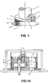
- Figure 1 shows that the extruding head is in column configuration.
- the extruding head 1 has an end surface 11, which will at least form a ringed sloping surface 12.
- the molding die 2 of this invention has a plane extruding surface 21.
- the end surface 11 of the extruding head 1 is arranged relative to the end surface 21 of this molding die 2, which forms a wedged extruding cavity 3 between the ringed sloping surface 12 of the extruding head 1 and the extruding surface 21 of the molding die 2.
- the coordination clearance of the end surface 11 of the extruding head 1 and the extruding surface 21 of the molding die 2 is less than about 3mm, but the coordination without clearance is the best.
- the radial height of the small end of the wedged extruding cavity 3 should be less than 3mm so as to form a bigger extruding force.
- This wedged extruding cavity 3 is arranged along the moving direction of the extruding head from the small end to the large end.
- a shearing force will be applied to the bio-substance material which enters the extruding cavity 3 during its movement, and then the material will be twisted, stretched, and flaked by the action of this shearing force.
- the friction of the material in the extruding cavity 3 will produce heat by the action of shearing force, which will raise its temperature to 70-110°C.
- the material at a temperature of 70-110°C, will move with the extruding head to be extruded to the small end of the wedged extruding cavity 3 and then into the molding die's 2 molding cavity 22.
- the extruding head of the extruding mechanism for this example of implementation can be a cylinder.
- the molding die 2 has a circular extruding end surface 21, and there is a molding cavity 22 which is arranged with the extruding end surface 21 at an angle.
- the directional section 23 can be arranged for the extruding cavity 3, which is arranged with the extruding surface of the molding die at an angle.
- the cavity body of this molding cavity 22 can be a cylinder, which will be arranged at the molding die 2 along the extruding surface 21. In this way, every molding action can produce multi-claviform combustion material.
- the material in the extruding cavity 3 continually enters into the molding cavity 22 by the action of shearing force to be molded into claviform state. Under the extruding action of the latter entering material, the previous material which enters into the molding cavity 22 will be continually extruded, and become more dense. At this point, a part of the bio-substance particles which have been grinded, twisted, and flaked in the extruding cavity will be deformed. After deformation, they will enter into the gap of the other part of the flaked particles to further mesh together. Consequently, based on this invention, a special structural mold and mechanical features are given to the molded product, which is better than that based on existing technology. Finally, the molded product is extruded from the outlet end of molding cavity.
- the extruding mechanism in this example of implementation is arranged in an inner cavity of extruding equipment, which is a cylinder inner cavity; the extruding head 1 can be driven by a power drive, which will be turning along a vertical axis.
- the molding die is a static design and a relative slipping movement mode will occur between the end surface 11, the slope surface 12, and the molding die's 2 extruding surface 21 which forms a relative movement due to differential speed between the extruding head 1 and the extruding surface 21 of the molding die 2.
- bio-substance particles extruded between these two surfaces will be ground, twisted, and flaked. As this occurs, the movement direction will force the bio-substance material to be extruded into the small end of the wedged extruding cavity 3, and finally the flake particles will be extruded into molding cavity 22 of the molding die.
- the difference between this example and example 1 is that there is no more than two ringed sloping surfaces 12 at the end surface 11 of the extruding head 1.
- This ringed sloping surface 12 and extruding plane surface 21 of the molding die 2 form the wedged extruding cavity 3, the number of which will be greater than two.
- These wedged extruding cavities 3 will be arranged from large end to small end in order to link together.
- the movement mode of this example of implementation can be the same as that adopted by example 1 of implementation, namely the extruding head can be driven by a power drive, which will be turning along a vertical axis. Its turning direction is along the extruding cavity 3 in the same direction from the small end to the large end, which will tend to make bio-substance material in the extruding cavity 3 move towards the small end of the extruding cavity.
- the molding die can be a static design, a relative slipping movement mode will occur between the end surface 11, the slope surface 12, and the extruding surface 21 of the molding die 2., which forms a relative movement due to differential speed between the extruding head 1 and the extruding surface 21 of the molding die 2.
- the molding method and molding mechanism in this example of implementation are also suitable for mold processing of bio-substance material. Because this example of implementation uses a multi-wedged extruding cavity 3, it can improve processing efficiency.
- the difference between this example and example 2 is that the movement mode of the extruding head 1 relative to the molding die of this example is different in that the molding die can be driven by a power drive, which will be turning along a vertical axis. Its turning direction is from the small end to the large end along the extruding cavity, which will tend to make bio-substance material in the extruding cavity 3 move towards the small end direction of the extruding cavity.
- the extruding head 1 can be a static design, causing a relative slipping movement mode to occur between the end surface 11, the slope surface of the extruding surface, 21 and the molding die 2. This forms a relative movement due to differential speed between the extruding head 1 and the extruding surface 21 of the molding die 2.
- the movement mode of the extruding head 1 relative to the molding die can be as follows.
- a power drive is turning both the extruding head 1 and the molding die 2 in the same direction from the small to the large end.
- their turning speeds differ in that N extruding ⁇ N molding , which forms a relative movement due to differential speed.
- the molding effect will be better when N extruding > N molding .
- the movement mode of the extruding head 1 relative to the molding die can be also as follows.
- a power drive is turning both the extruding head 1 and the molding die 2.
- the turning direction of the extruding head 1 is from the small end to the large end, but the turning direction of the molding die 2 can be contrary to that of extruding head 1.
- both turning speeds can be either the same or different.
- the extruding head 4 in this example of implementation is a board configuration.
- This extruding head 4 has an end surface 41 with board configuration, which forms at least an approximate linear slope surface 42.
- the molding die 5 has a plane extruding surface 51.
- the arrangement of the end surface 41 of the extruding head 4 is relative to the end surface 51 of the molding die 5, which can form a wedged extruding cavity 3 between the approximate linear slope surface 42 of the extruding head 4 and the extruding surface 51 of the molding die 5.
- the large end of this extruding cavity 3 is higher than small end. The large end will be connected directly with the material inlet 31, and incompact material can enter into the wedged extruding cavity 3 from the inlet 31.
- the coordination clearance between the end surface 41 of the extruding head 4 and the extruding surface 51 of the molding die 5 is less than 3mm.
- the best coordination clearance is no clearance, which will make radial height of the small end for the wedged extruding cavity 3 smaller than 3mm so as to form a larger extruding force.
- this extruding head 4 will be from small to large along the direction of its movement, when the extruding head 4 relative to the extruding surface 51 of the molding die 5 moves, the material which enters into extruding cavity 3 is applied to a shearing force during the relative movement between the extruding head 4 and the molding die 5, which is ground, twisted, and flaked by the action of shearing force.
- the friction of the material in the extruding cavity 3 will produce heat by the action of the shearing force, which will increase its temperature to approximately 70-110°C, at the same time, the material, now at a temperature of 70 ⁇ 110°C, will move with the extruding head to be extruded to the small end of the wedged extruding cavity 3 then into the molding cavity 52 of the molding die 5.
- the molding cavity 52 is arranged as a flute along the plane extruding surface 51 of the molding die 5.
- the molding cavity 52 can be multi-shape, such as polygon, roundness and other anomalistic shape.
- the extruding head 1 can be driven by a power drive for linear movement, and molding die can be a static design.
- a relative slipping movement mode will occur between its slope end surface 41 and the extruding surface 51 of the molding die 5, which forms a relative movement due to differential speed between the extruding head 4 and the extruding surface 51 of the molding die 5.
- the bio-substance material particles extruded will be ground, twisted, and flaked.
- bio-substance material will finally be extruded into the molding cavity 52 of the molding die 5.
- the molding cavity 52 is a flute arranged on the extruding surface, bio-substance material in the extruding cavity 3 is stretched to become flake material, which is extruded into the flute of the molding cavity 52.
- the material, now in the form of a sandwich, will then be pressed into the molding cavity 52 by the small end of the extruding cavity 3.
- the molding feature in this example of implementation is that because the molding cavity is a flute where the front end is a hard flute wall made from rigid material, the bio-substance material which is extruded into the flute of the molding cavity will be impacted within its force transfer distance. Therefore not only will the molded product have the same structural mold as the above mentioned examples, but its density will be much more uniform and stable. In effect, the molding method and molding mechanism in this example of implementation will be much more suitable for the processing of board material and other available moldable material.
- the shape of the molding cavity 52 in this example of implementation can be designed according to the required shape of the product.
- the extruding head 4 can be driven by the power drive to create a linear movement relative to the molding die 5.
- the molding die is a static design so as to form a movement mode caused from differential speed.
- the molding die 5 can be driven by power drive to create a linear movement relative to the extruding head 4, where the direction of the movement is from the large end of the extruding cavity 3 to the small end.
- the extruding head is a static design.
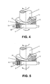
- the extruding head 4 and molding die 5 can move simultaneously, as shown in Figure 7.
- the direction of their movement can be either contrary or same, where N extruding ⁇ N molding , which forms a relative movement caused from differential speed.
- the molding effect will be better when N extruding > N molding .
- the molding option and above mentioned movement mode of this example of implementation can arrange two or greater extruding heads 4.
- An extruding cavity is formed between this slope surface 42 and the end surface 51 of the molding die.
- the molding die 5 will extrude the bio-substance material through the previous extruding head 4, which will be pressed and stretched in the cavity 51 arranged at the end surface 51.
- the molding die will turn at an angle to extrude another layer of material into molding cavity 52 through the next extruding head 4. Because the layer-built flake material in the folding state in the extruding cavity enters into molding cavity 52 at a different angle, every two layers of molding structure will be in a state of intertexture.
- the previous layer of material which enters into the molding cavity 52 will be extruded by the latter layer of material for further extruding.
- Tests have proven that there is an excellent linking strength for the molding board and reutilized moldable material by using this method, therefore, the molding product produced by using the method described in this example of implementation has excellent linking strength as well. This can minimize the use of any chemical binder, or even eliminate the need to use any binder in furniture fabrication, board or profiled material for decoration, or block-shaped combustible material.
- the extruding head 4 in this example of implementation is a board configuration.
- This extruding head 4 has an end surface 41 with board configuration, which forms two approximate linear slope surfaces 42.
- a plane space 43 is arranged between these two slope surfaces 42.
- the plane space 43 is higher than the end surface 41, which forms the extruding head with ladder configuration.
- the molding die 5 has a plane extruding surface 51.
- the arrangement of the end surface 41 of the extruding head 4 is relative to the end surface 51 of the molding die 5, which can form a wedged extruding cavity 3 between the approximate linear slope surface 42 of the extruding head 4 and the extruding surface 51 of the molding die 5.
- the large end of this extruding cavity 3 is higher than small end. This large end will be connected directly with material inlet 31, and incompact material can enter into wedged extruding cavity 3 from the inlet 31.
- the movement mode in the above example of implementation can be used for this example of implementation.
- the molding principle in this example of implementation is that bio-substance material is ground, twisted, and stretched to be a layer-built flake material in folding state by the action of a shearing force, which will be extruded into the flute of the molding cavity 52. There it will be pressed by the plane space 43 to be a molded product. When the extruding head 4 moves continuously relative to the molding die 5, the slope surface 42 of the plane space 43 will continue to extrude the bio-substance material in the molding cavity 52.
- This example of implementation can be used for making usable moldable material, which has higher thickness and intertexture structural model.
- the feedstock of the bio-substance before molding process, should be in an incompact state.
- the extruding head is made up of a rolling body.
- the wedged extruding cavity is formed between the rolling surface of the extruding head and the extruding surface of the molding die, which forms a rolling extruding mode.
- the extruding head 6 is a circular column which can turn around its center of rotation, where the circumferential surface forms the rolling surface 61.
- the extruding surface 71 of the molding die 7 is a plane design.
- the rolling surface 61 of the extruding head 6 is arranged relative to the extruding surface 71 of the molding die 7, and a wedged extruding cavity is formed between the extruding head 6 and the extruding surface 71 of the molding die 7.
- the coordination clearance between the rolling surface 61 of the extruding head 6 and the extruding surface 71 of the molding die 7 will be less than 3mm, where the best is a coordination one with no clearance.
- Relative motion is caused by differential speed between the rolling surface 61 of the extruding head 6 and the extruding surface 71 of the molding die 7.
- the material which enters into the extruding cavity 3 will be applied to a shearing force.
- the material is ground, stretched, and flaked by the action of the shearing force.
- the action of the shearing force will produce heat to increase the temperature of the material to 70-110°C.
- the material is extruded to the small end of wedged extruding head 3 and then into the molding cavity 72 of the molding die 7.
- the molding cavity 72 which is arranged at an angle to the extruding end surface 21 of the molding die 7 for the processing of bio-substance combustion material.
- the molding cavity 72 can be a column-shaped cavity, which is arranged along the extruding surface 71 so that multi-claviform combustion material can be molded every time.
- the raw material in the extruding cavity 3 will continuously enter the molding cavity 72 to be molded to a claviform body by the action of shearing force.
- Previous bio-substance material that enters into molding cavity 72 will be extruded by the latter bio-substance material for further extruding, which will increase its density, and part of bio-substance particles which have been in the extruding cavity 3 to be ground, twisted, and flaked will be deformed. After deformation, the material will enter the gap with another part of flake particles to further mesh to each other up and down. Consequently, it gives the product a special structural model , which will have better mechanical features than that of the product produced by existing molding technology. Finally, the molded combustion material will be extruded from the outlet of the molding cavity 72.
- the extruding head 6 can be driven by a power drive, and the molding die 7 can be a static design.
- a relative rolling movement mode will be produced between the rolling surface 61 of the extruding head 6 and the extruding surface 71 of the molding die 7. It can also move in the direction as shown in Figure 10, in which the extruding head 6 rotate along its vertical axis from the large end to the small end, thus creating a relative movement caused by differential speed between the extruding head 6 and the extruding surface 71 of the molding die 7.
- the bio-substance particles which are extruded in extruding cavity will be ground, twisted, stretched, and flaked.
- the movement direction will force the material to be extruded to the small end of wedged extruding cavity 3 and finally extruded into the molding cavity 72 for molding.
- the extruding head 6 in this example of implementation can still turn around its center of rotation driven by a power and the molding die 7 is a linear movement driven by power. Because of this, a relative rolling movement mode will be produced due to differential speed between the rolling surface 61 of the extruding head 6 and the extruding surface 71 of the molding die 7. Because this relative movement is a compositive movement produced by self rotation of the extruding head 6 along its axis of rotation and linear movement of the molding die 7, the linear speed of two extruding surfaces for extruding bio-substance material differs, which forms a shearing force applied to the bio-substance material extruded in between.
- the direction of self-rotation for the rolling surface 61 of the extruding head 6 is contrary to the direction of the movement for the molding die 7, which makes two extruding surfaces of wedged extruding cavity have the linear speed with contrary direction.
- Another implementation mode in this example of implementation is that the direction of self rotation for the rolling surface 61 of the extruding head 6 is the same as the direction of the movement for the molding die 7; namely, two extruding surfaces of the wedged extruding cavity have the linear speed with same direction but different linear speed.
- N extruding ⁇ N molding it forms a relative rolling movement mode due to the differential speed. The molding effect will be even better when N extruding > N molding .
- the molding cavity 73 is a flute arranged along the surface of the plane extruding surface 71 of the molding die 7.
- a relative movement due to differential rolling speed will occur between the rolling surface 61 of the extruding head 6 and the extruding surface 71 of the molding die 7, which will cause the extruded bio-substance material to be ground, twisted, stretched, and flaked.
- the bio-substance material will finally be extruded into the flute of the molding cavity 73 for the molding die 7.
- the molding cavity 73 is arranged in the flute of the extruding surface 71, the bio-substance material which has been stretched into a flake material will be extruded as a floc into the flute of the molding cavity 73 and pressed from the small end of the extruding cavity 3 in the molding cavity 73 to become a layered structure.
- the molding feature in this example of implementation is due to the fact that the molding cavity is a flute, and the front end of the flute is a hard wall made from rigid material where the material will be extruded.
- the bio-substance material which will be extruded into molding cavity 73 will be pressed within its force transfer distance so that not only will only the molded product have the same structural model as in the above mentioned examples of implementation, but also its density will be much more uniform and it will be much stronger. Therefore, the molding method and molding mechanism in this example of implementation are much more suitable for board material and processing other available material.
- the shape of the molding cavity 73 in this example of implementation can be designed according to the shape of molded products.
- the movement mode in this example of implementation can be the same as the compositive movement mode in the example of implementation 8.
- two or greater extruded heads 6 can be arranged.
- the molding die 7 passes the previous extruding head 6 and one more layer of bio-substance material is extruded into molding cavity 73, it will turn at an angle to pass the next extruding head 6. Then one more layer of bio-substance material will be extruded into molding cavity 73. Because the bio-substance material, which has been stretched into a flake in the extruding cavity, enters into molding cavity 73 from different angles, every two layers of molded structure model will be in the state of intertexture.
- the previous layer of bio-substance material which enters molding cavity 73 will be extruded by the latter layer of material.
- Tests have proven that there is an excellent linking strength for the molding board and reutilized moldable material by using this method, therefore, the molding product produced by using the method described in this example of implementation has excellent linking strength as well. This can minimize the use of any chemical binder, or even eliminate the need to use any binder in furniture fabrication, board or profiled material for decoration, or block-shaped combustible material.
- the extruding head 6 in this example of implementation is a circular column. This extruding head 6 can rotate around its center of rotation and is power driven.
- the circumferential surface forms a rolling surface 61.
- the molding die 8 can be made from a canister body, where its inner surface forms a circular extruding surface 81 and the curvature of extruding surface 81 is greater than that of rolling surface 61 of the extruding head.
- the rolling surface 61 of the extruding head is arranged relative to the extruding surface 81 of the molding die 8, these two curvilinear surfaces between the extruding head 6 and the extruding surface 81 of the molding die 8 will form a wedged extruding cavity 3.
- the coordination clearance between the rolling surface 61 of the extruding head 6 and the extruding surface 81 of the molding die 8 is less than 3mm, where the best coordination is no clearance.
- this molding cavity 82 which is arranged at an angle to the extruding end surface 81 of the molding die 8.
- this molding cavity 82 can be a columned cavity, which is arranged in the molding die 8 along the extruding surface.
- the material in the extruding cavity 3 will continuously enter the molding cavity 82 by the action of shearing force to be molded as a claviform body. Previous material in the molding cavity will be continuously extruded by the extruding action of latter entering material, which will make the density of the material increase.
- the extruding head 6 in this example of implementation can be power driven which will turn around its vertical axes of rotation.
- the molding die 8 is a static design, thus a relative rolling movement mode between the rolling surface 61 of the extruding head 6 and the extruding surface 81 of the molding die 8 will occur, which forms a relative movement due to the differential speed between the extruding head 6 and the extruding surface 81 of the molding die 8.
- the bio-substance particles which are extruded in the extruding cavity, will be ground, twisted, stretched, and flaked.
- the movement direction will force the material to be extruded to the small end of the wedged extruding cavity 3, and finally into the molding cavity 82 of the molding die.
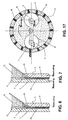
- the rotating direction of self-rotation for the rolling surface 61 of the extruding head 6 can be the same as that of the molding die 8, which makes the two extruding surfaces of the wedged extruding cavity have linear speed with contrary direction, as shown in Figure 12 and 13.
- the extruding head 9 in this example of implementation is a cone, which can rotate around its center of rotation and is power driven.
- the circumferential surface forms a rolling surface 91.
- the molding die 10 can be made from a conic body, where its inner surface forms a conic extruding surface 101 and the curvature of the extruding surface 101 is greater than that of the rolling surface 91 of the extruding head.
- the rolling surface 91 of the extruding head 9 is arranged relative to the extruding surface 101 of the molding die 10, these two curvilinear surfaces between the extruding head 9 and the extruding surface 101 of the molding die 10 will form a wedged extruding cavity 3.
- the extruding head 9 in this example of implementation can be power driven, which will rotate surrounding its vertical axis of rotation.
- the molding die 10 is a static design, thus, a relative rolling movement mode between the rolling surface 91 of the extruding head 9 and the extruding surface 101 of the molding die 10 will occur. Also, the extruding head 9 and the molding die 10 will rotate along self axes, respectively, with the same or contrary direction. When the rotations are in the same direction, N extruding ⁇ N molding , it forms a relative movement due to the differential speed between the extruding head 9 and the extruding surface 101 of the molding die 10.
- the extruding head 6 in this example of implementation is a circular column. This extruding head 6 can rotate around its center of rotation and is power driven.
- the circumferential surface forms a rolling surface 61.
- the molding die 8 can be made from a canister body, where its inner surface forms a circular extruding surface 81 and the curvature of the extruding surface 81 is greater than that of the rolling surface 61 of the extruding head.
- the rolling surface 61 of the extruding head is arranged relative to the extruding surface 81 of the molding die 8, these two curvilinear surfaces between the extruding head 6 and the extruding surface 81 of the molding die 8 will form a wedged extruding cavity 3.
- more than two extruding heads 6 can be arranged, where every extruding head is power driven and will self-rotate along its vertical axis.
- the molding die 8 is a static design and the rolling surface 61 of the multi-extruding head 6 will form more than two wedged extruding cavities 3 relative to the extruding surface 81 of the molding die 8.
- the movement mode in this example of implementation can be the same and the molding principle is the same as that in the example of implementation 10. Therefore, unnecessary details will be omitted.
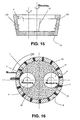
- the movement mode as shown in Figure 16, can be adopted also for this example of implementation where the extruding head 6 will self-rotate along its axis of rotation, and the rotation of the molding die 8 is power driven.
- the relative movement between the extruding head and the molding die is a compositive movement from the self-rotation of the extruding head along its axis of rotation and the revolution of the extruding head relative to the molding die as the center of rotation.
- the extruding head 6 in this example of implementation is a circular column. This extruding head 6 can rotate around its center of rotation and is power driven.
- the circumferential surface forms a rolling surface 61.
- the molding die 8 can be made from a canister body, where its inner surface forms a circular extruding surface 81 and the curvature of extruding surface 81 is greater than that of the rolling surface 61 of the extruding head.
- the rolling surface 61 of the extruding head is arranged relative to the extruding surface 81 of the molding die 8, the two curvilinear surfaces between the extruding head 6 and the extruding surface 81 of the molding die 8 will form a wedged extruding cavity 3.
- more than two extruding heads 6 can be arranged and every extruding head is power driven and will self-rotate along its vertical axis.
- the molding die 8 is a static design and the rolling surface 61 of the multi-extruding head 6 will form more than two wedged extruding cavities 3 relative to the extruding surface 81 of the molding die 8.
- the movement mode in this example of implementation has the direction of self-rotation for the extruding head 6 along its axis of rotation is spinning contrary to that of the revolution of the extruding head relative to the molding die as the center of rotation.
- the self-rotation of the extruding head 6 along its axis of rotation and the revolution of the extruding head 6 relative to the molding die 8 as the center of rotation can be a movement of differential speed but in the same direction.
- the linear speed of self-rotation for the extruding head 6 along its axis of rotation is greater than the revolution speed of the extruding head 6 relative to the molding die 8.
Landscapes
- Chemical & Material Sciences (AREA)
- Organic Chemistry (AREA)
- Engineering & Computer Science (AREA)
- Zoology (AREA)
- Wood Science & Technology (AREA)
- Life Sciences & Earth Sciences (AREA)
- Mechanical Engineering (AREA)
- Chemical Kinetics & Catalysis (AREA)
- Biochemistry (AREA)
- General Health & Medical Sciences (AREA)
- General Chemical & Material Sciences (AREA)
- Health & Medical Sciences (AREA)
- Biotechnology (AREA)
- Bioinformatics & Cheminformatics (AREA)
- General Engineering & Computer Science (AREA)
- Microbiology (AREA)
- Genetics & Genomics (AREA)
- Oil, Petroleum & Natural Gas (AREA)
- Extrusion Moulding Of Plastics Or The Like (AREA)
- Processing Of Solid Wastes (AREA)
- Fodder In General (AREA)
- Dry Formation Of Fiberboard And The Like (AREA)
Abstract
Description
Claims (75)
- A molding method for moldable bio-substance material, comprising:(1) crushing the bio-substance materials into an incompact state and then extruding them for further molding through a molding die;(2) forming at least a wedged extruding cavity between an extruding head and an extruding surface of the molding die;(3) passing the bio-substance materials in the incompact state through an action of a relative movement between the extruding head and the extruding surface of the molding die at differential speeds; and(4) grinding the particles of the bio-substance materials extruded between the extruding head and the extruding surface, and then twisting, stretching and flaking said bio-substance materials, and meanwhile extruding the same to a small end of the wedged extruding cavity and further forcing them into a molding cavity of the molding die to be molded.
- The molding method for moldable bio-substance material according to claim 1, wherein the water content of said moldable bio-substance materials is higher than 6% in its extruding state, and the best is 20%~50% for extrusion.
- The molding method for moldable bio-substance material according to claim 1, wherein said wedged extruding cavity can be formed between an end surface of the extruding head and the extruding surface of the molding die, and said bio-substance materials enter the extruding cavity from a large end of said wedged extruding cavity.
- The molding method for moldable bio-substance material according to claim 3, wherein the end surface of the extruding head forms at least a slope surface; the wedged extruding cavity is formed between said slope surface and the extruding surface of the molding die; the extruding cavity is arranged along the opposite direction of the movement of the extruding head from the large end to a small end thereof; and said bio-substance materials are grinded, twisted up, and extruded to the small end of the wedged extruding cavity and meanwhile extruded into the molding cavity when the extruding head moves relatively to the extruding surface of the molding die.
- The molding method for moldable bio-substance material according to claim 4, wherein said end surface of the extruding head and the extruding surface of the molding die have, in between, a coordinative clearance of less than 3mm.
- The molding method for moldable bio-substance material according to claim 5, wherein said end surface of the extruding head and the extruding surface of the molding die do not have a coordinative clearance in between.
- The molding method for moldable bio-substance material according to claim 3 or 4, wherein said relative movement of the extruding head and the extruding surface of the molding die is a relative slipping movement.
- The molding method for moldable bio-substance material according to claim 7, wherein during said relative movement between the extruding head and the extruding surface of the molding die, the extruding head can turn along its vertical axes while the molding die is static.
- The molding method for moldable bio-substance material according to claim 3 or 4, wherein said relative movement between the extruding head and the extruding surface of the molding die is a relative parallel movement in between.
- The molding method for moldable bio-substance material according to claim 9, wherein during said relative movement one of the extruding head and the molding die us still, while the other is moving relatively parallel to the static one.
- The molding method for moldable bio-substance material according to claim 9, wherein said parallel movement between the extruding head and the molding die is caused by their opposite movements.
- The molding method for moldable bio-substance material according to claim 9, wherein said parallel movement between the extruding head and the molding die is caused by their differential speed moving in the same direction.
- The molding method for moldable bio-substance material according to claim 3, wherein said molding cavity is arranged at an angle toward the end surface of the molding die.
- The molding method for moldable bio-substance material according to claim 13, wherein said molding cavity arranged at an angle to the end surface of the molding die has an oriented section.
- The molding method for moldable bio-substance material according to claim 9, wherein said molding cavity is a flute distributed along the extruding surface of the molding die.
- The molding method for moldable bio-substance material according to claim 1, wherein said extruding head is made from a rolling body, and the wedged extruding cavity is formed between the rolling surface of the extruding head and the extruding surface of the molding die.
- The molding method for moldable bio-substance material according to 16, wherein said extruding head made from the rolling body is a cylinder.
- The molding method for moldable bio-substance material according to 16, wherein said extruding head made from the rolling body is conic.
- The molding method for moldable bio-substance material according to claim 16 or 17 or 18, wherein said relative movement between the extruding head and the molding die is a composite movement formed between an axial self-rotation of the extruding head and a linear movement of the molding die.
- The molding method for moldable bio-substance material according to claim 16 or 17 or 18, wherein one of the extruding head and the molding die is static, while the other moves relatively to the static one.
- The molding method for moldable bio-substance material according to claim 19, wherein the direction of said axial self-rotation of the extruding head is opposite to the direction of the linear movement of the molding die.
- The molding method for moldable bio-substance material according to claim 21, wherein said relative movement is a differential speed movement in the same direction of the axial self-rotation of the extruding head and the linear movement of the molding die.
- The molding method for moldable bio-substance material according to claim 22, wherein the linear speed of said axial self-rotation of the extruding head is larger than the linear moving speed of the molding die.
- The molding method for moldable bio-substance material according to claim 16 or 17 or 18, wherein said relative movement between the extruding head and the molding die is composed of an axial self-rotation of the extruding head and a revolution of the extruding head relatively using the molding die as an axe of the rotation.
- The molding method for moldable bio-substance material according to claim 24, wherein the relative movement of the extruding head and the molding die is composed of the axial self-rotation of the extruding head and the revolution of the extruding head relative to the molding die as an axe of rotation.
- The molding method for moldable bio-substance material according to claim 24, wherein said relative movement of the extruding head to the molding die is composed of the axial self-rotation of the extruding head and an axial self-rotation of the molding die.
- The molding method for moldable bio-substance material according to claim 25, wherein the movements of the extruding head and the molding die are in opposite direction between the axial self-rotation of the extruding head and the revolution of the extruding head using the molding die as a rotation axe.
- The molding method for moldable bio-substance material according to claim 25, wherein the relative movement is a differential speed movement in the same direction between the said axial self-rotation of the extruding head and the revolution of the extruding head using molding die as a rotation axe.
- The molding method for moldable bio-substance material according to claim 28, wherein the linear speed of the axial self-rotation of the extruding head is greater than the revolution speed of the extruding head using the molding die as the rotation axe.
- The molding method for moldable bio-substance material according to claim 19, wherein the extruding surface of the molding die is a plane; said wedged extruding cavity is formed between the rolling surface of the extruding head and the extruding surface of the molding die, and the materials enter into the extruding cavity along the large end of the wedged extruding cavity.
- The molding method for moldable bio-substance material according to claim 24, wherein said extruding surface of the molding die is an arc, and the curvature radius of the extruding arc surface is greater than the rotation radius of the extruding head; and said wedged extruding cavity is formed between the rolling surfaces of the extruding head and the extruding surface of the molding die, and the bio-substance materials enter into the extruding cavity along the large end of the wedged extruding cavity.
- The molding method for moldable bio-substance material according to claim 30 or 31, wherein a large end of the wedged extruding cavity has an opening facing upwards, and the bio-substance materials are extruded into the extruding cavity and moved to a small end by gravity and friction produced between the extruding head and the extruding surface.
- The molding method for moldable bio-substance material according to claim 16 or 17 or 18, wherein said molding cavity of the molding die is arranged at an angle relatively to the extruding surface of the molding die.
- The molding method for moldable bio-substance material according to claim 33, wherein an oriented section is set for the molding cavity which is arranged at an angle to the extruding surface of the molding die.
- The molding method for moldable bio-substance material according to any of claims 16 to 18, wherein said molding cavity of the molding die is distributed over multiple flutes on the extruding surface of the molding die.
- , The molding method for moldable bio-substance material according to any claim above, wherein the said molded product can be either air dried or stove dried.
- A molding apparatus for moldable bio-substance material, comprising(1) at least an extruding head driven by power;(2) a molding die having an extruding surface and a molding cavity;(3) a wedged extruding cavity formed at least between the extruding head and the extruding surface of the molding die, and having a large end and a small end; and(4) a material inlet provided at the large end of the wedged extruding cavity, through which particles of the bio-substance materials enter into the extruding cavity to be grinded, twisted up, stretched, flaked due to an action of relative movement between the extruding head and the extruding surface of the molding die, and meanwhile to be molded in the molding cavity of the molding die.
- The molding apparatus according to claim 37, wherein said wedged extruding cavity is formed between the end surface of the extruding head and the extruding surface of the molding die, and the bio-substance material enter the extruding cavity from the large end.
- The molding apparatus according to claim 38, wherein at least one slope surface is formed on the end surface of extruding head; the wedged extruding cavity is formed by this slope surface and the extruding surface of the molding die; the extruding cavity is arranged along an opposite direction of the large end to small end movement of the extruding head; and the material will be grinded, twisted up, and at the same time extruded to the small end of extruding cavity and then into molding cavity, when the extruding head moves relatively to the extruding surface of the molding die.
- The molding apparatus for moldable bio-substance material according to claim 39, wherein the slope surface of the said end surface of the extruding head can be two or more than two, the best to be a uniform distribution.
- The molding apparatus for moldable bio-substance material according to claim 39, wherein the coordination clearance between the said end surface of the extruding head and the said extruding surface of the molding die is less than 3mm.
- The molding apparatus for moldable bio-substance material according to claim 41, wherein there is no coordination clearance between the said end surface of the extruding head and the said extruding surface of the molding die.
- The molding apparatus for moldable bio-substance material according to claim 39 or 40, wherein the said relative movement between the end surface of the extruding head and the extruding surface of the molding die can be a relative slipping movement.
- The molding apparatus for moldable bio-substance material according to claim 43, wherein the said relative movement includes an axial rotation of the extruding head and the static state of the molding die.
- The molding apparatus for moldable bio-substance material according to claim 40 or 44, wherein the said slope surface of the end surface of the extruding head can be annularly distributed with the axe of its rotation.
- The molding apparatus for moldable bio-substance material according to claim 39, wherein the said relative movement between the extruding head and the molding die can be relatively parallel.
- The molding apparatus for moldable bio-substance material according to claim 46, wherein for the said extruding head and said molding die, one of which is static and the other one is moving parallel relative to the static one.
- The molding apparatus for moldable bio-substance material according to claim 46, wherein the said relatively parallel movement between the extruding head and the molding die is the contrary movement in between.
- The molding apparatus for moldable bio-substance material according to claim 46, wherein the said relatively parallel movement between the extruding head and the molding die is the differential speed movement in the same direction.
- The molding apparatus for moldable bio-substance material according to claim 46, wherein the said slope surface of the end surface for the extruding head can be vertically distributed according to the direction of its movement.
- The molding apparatus for moldable bio-substance material according to claim 39, wherein the said the end surface of the molding cavity is set at an angle to the molding die.
- The molding apparatus for moldable bio-substance material according to claim 51, wherein an oriented section could be set in the said the extruding cavity, which is arranged at an angle to the extruding surface of the molding die.
- The molding apparatus for moldable bio-substance material according to claim 51, wherein the large end height of the said molding cavity oriented section is no greater than 10mm.
- The molding apparatus for moldable bio-substance material according to claim 39 or 46, wherein the said molding cavity can be composed of multiple flutes distributing along the extruding surface of the molding die.
- The molding apparatus for moldable bio-substance material according to claim 37, wherein the said extruding head can be composed of the rolling body; the said wedged extruding cavity is formed between the rolling surface of the extruding head and the extruding surface of the molding die.
- The molding apparatus for moldable bio-substance material according to claim 55, wherein the said rolling body made of the extruding head, can be a cylinder.
- The molding apparatus for moldable bio-substance material according to claim 55, wherein the said rolling body made of the extruding head, can be a cone.
- The molding apparatus for moldable bio-substance material according to claim 55, wherein the said extruding surface of the molding die is set as a plane; the said wedged extruding cavity is formed between the rolling surface of the extruding head and the extruding surface of the molding die; the material enters the extruding cavity from the large end of the wedged extruding cavity.
- The molding apparatus for moldable bio-substance material according to claim 55, wherein the said extruding surface of molding die has the shape of an arc; the curvature radius of the extruding arc surface is greater than the rotation radius of the extruding head; the said wedged extruding cavity is formed between rolling surface of the extruding head and extruding surface of the molding die; the material enters the extruding cavity through the large end of wedged extruding cavity.
- The molding apparatus for moldable bio-substance material according to claim 58 or 59, wherein the said large end of wedged extruding cavity has upward facing opening; the material is extruded to enter the extruding cavity and then to the small end by its gravity and friction generated between the extruding head and the extruding surface.
- The molding apparatus for moldable bio-substance material according to claim 55, 56 or 57, wherein the said relative movement between the extruding head and the molding die is a compositive movement, which includes the axial self-rotation of the extruding head and the linear movement of the molding die.
- The molding apparatus for moldable bio-substance material according to claim 55, 56 or 57, wherein for the said extruding head and molding die, one is static, the other has relative movement relative to the static one.
- The molding apparatus for moldable bio-substance material according to claim 61, wherein the said direction of extruding head axial self-rotation is contrary to the linear movement direction of the molding die.
- The molding apparatus for moldable bio-substance material according to claim 61, wherein the said relative movement is the differential speed movement in the same direction between the axial self-rotation of the extruding head and linear movement of the molding die.
- The molding apparatus for moldable bio-substance material according to claim 64, wherein the linear speed of the said extruding head axial self-rotation, is larger than the linear moving speed of the molding die.
- The molding apparatus for moldable bio-substance material according to claim 55, 56 or 57, wherein the said relative movement between the extruding head and molding die, is a composition movement including the axial self-rotation of the extruding head and the revolution movement of the extruding head using molding die as rotation axle.
- The molding apparatus for moldable bio-substance material according to claim 66, wherein the said relative movement between the extruding head and the molding die, is a composition movement including the axial self-rotation of the extruding head and the revolution movement of the extruding head using extruding die as rotation axle.
- The molding apparatus for moldable bio-substance material according to claim 66, wherein the said relative movement between the extruding head and the molding die, is a composition movement including the axial self-rotation of the extruding head and the axial rotation of the molding die.
- The molding apparatus for moldable bio-substance material according to claim 67 or 68, wherein the said direction of the extruding head axial self-rotation is contrary to that of the revolution movement of extruding head using molding die as rotation axle.
- The molding apparatus for moldable bio-substance material according to claim 67 or 68, wherein it is the same direction differential speed movement that is between the said axial self-rotation of the extruding head and the revolution movement of the extruding head using molding die as rotation axle.
- The molding apparatus for moldable bio-substance material according to claim 70, wherein the said linear speed of the extruding head axial self-rotation is greater than the revolution speed of the extruding head relative to the molding die.
- The molding apparatus for moldable bio-substance material according to any claim from 55 to 71, wherein the said molding cavity of the molding die can be set at an angle relative to the extruding surface of the molding die.
- The molding apparatus for moldable bio-substance material according to claim 72, wherein an oriented section can be set on the said molding cavity, which is set at an angle to the extruding surface of the molding die.
- The molding apparatus for moldable bio-substance material according to claim 73, wherein the height of the large end is no greater than 10mm in the said oriented section of the molding cavity.
- The molding apparatus for moldable bio-substance material according to any claim from 55 to 72, wherein the said molding cavity of the molding die can be distributed among multiple flutes on the extruding surface of the molding die.
Applications Claiming Priority (1)
| Application Number | Priority Date | Filing Date | Title |
|---|---|---|---|
| PCT/CN2002/000506 WO2004009340A1 (en) | 2002-07-19 | 2002-07-19 | A process and a device for shaping the loosen material of raw vegetable matter |
Publications (2)
| Publication Number | Publication Date |
|---|---|
| EP1541328A1 true EP1541328A1 (en) | 2005-06-15 |
| EP1541328A4 EP1541328A4 (en) | 2008-12-17 |
Family
ID=30450057
Family Applications (1)
| Application Number | Title | Priority Date | Filing Date |
|---|---|---|---|
| EP02752958A Withdrawn EP1541328A4 (en) | 2002-07-19 | 2002-07-19 | A process and a device for shaping the loosen material of raw vegetable matter |
Country Status (7)
| Country | Link |
|---|---|
| US (1) | US20060082026A1 (en) |
| EP (1) | EP1541328A4 (en) |
| JP (1) | JP2005532904A (en) |
| CN (1) | CN1282538C (en) |
| AU (1) | AU2002313871A1 (en) |
| CA (1) | CA2492881A1 (en) |
| WO (1) | WO2004009340A1 (en) |
Cited By (5)
| Publication number | Priority date | Publication date | Assignee | Title |
|---|---|---|---|---|
| WO2008009167A1 (en) * | 2006-07-10 | 2008-01-24 | Zhanbin Che | Cuniform extruding mold, supporting body and pattern die |
| ITBS20080138A1 (en) * | 2008-07-18 | 2010-01-19 | Co Ma Fer Macchine S P A | PELLET MAKING MACHINE |
| EP2253885A3 (en) * | 2009-05-08 | 2014-12-17 | Pellet Technology LLC | Biomass pelletizing process |
| CN108816154A (en) * | 2018-06-07 | 2018-11-16 | 田力 | A kind of biomass fuel machine-shaping device |
| CN109367109A (en) * | 2018-11-09 | 2019-02-22 | 内蒙古科技大学 | A crank rocker plunger type biomass compressor |
Families Citing this family (15)
| Publication number | Priority date | Publication date | Assignee | Title |
|---|---|---|---|---|
| WO2006047933A1 (en) * | 2004-10-31 | 2006-05-11 | Caidong Qin | Biomass fuel block and the apparatus and method for its burning |
| DE102007044584A1 (en) | 2007-09-19 | 2009-04-16 | Fachhochschule Hannover | Production of fuel pellets, involves extruding undried starting material containing a binder, e.g. thermoplastic biopolymer, and a combustible material, e.g. wood chips, and removing liquid before discharge |
| SE534484C2 (en) * | 2009-02-16 | 2011-09-06 | Zilkha Biomass Fuels Llc | Process for producing fuel pellets from a biological raw material, an arrangement therefor and fuel pellets |
| RU2431568C2 (en) * | 2009-03-31 | 2011-10-20 | Государственное образовательное учреждение высшего профессионального образования "Пятигорский государственный технологический университет" | Briquetting machine |
| WO2010130095A1 (en) * | 2009-05-14 | 2010-11-18 | 嘉兴市禾森建材有限公司 | Plant binding agent powder and its preparation method |
| RU2412819C1 (en) * | 2009-12-09 | 2011-02-27 | Государственное образовательное учреждение высшего профессионального образования "Оренбургский государственный университет" | Granulator press |
| CN101797490B (en) * | 2010-02-02 | 2012-04-18 | 邢献军 | Biomass granulation equipment |
| CN102294836B (en) * | 2010-06-23 | 2015-08-12 | 车战斌 | The forming method of reproducible biological material |
| EP2701900B1 (en) * | 2011-04-29 | 2017-08-23 | Andritz AG | Pellet mill |
| CN102533378A (en) * | 2012-03-05 | 2012-07-04 | 如东中科新能源科技有限公司 | Process for producing biomass cured and molded fuel |
| CN103419394A (en) * | 2013-09-02 | 2013-12-04 | 潍坊金丝达环境工程股份有限公司 | Garbage block forming machine capable of realizing resource utilization |
| CN104479783A (en) * | 2014-11-28 | 2015-04-01 | 常熟市协新冶金材料有限公司 | Forming method of biomass fuel |
| CN107880961A (en) * | 2016-09-30 | 2018-04-06 | 杨丰铭 | Method for producing biomass fuel |
| CN108102760B (en) * | 2018-01-24 | 2024-08-02 | 南阳理工学院 | Biomass solid particle forming machine |
| CN116371293B (en) * | 2023-04-18 | 2023-09-22 | 扬州日发生物设备有限公司 | Quick granulator is used in production of fodder granule |
Family Cites Families (19)
| Publication number | Priority date | Publication date | Assignee | Title |
|---|---|---|---|---|
| CH444461A (en) * | 1966-03-24 | 1967-09-30 | List Heinz | Process for the production of moldings from powder or paste material |
| FR1600266A (en) * | 1968-01-17 | 1970-07-20 | ||
| DE3213829A1 (en) * | 1982-04-15 | 1983-10-27 | Masol GmbH, 3320 Salzgitter | Briquette for burning and heating purposes |
| DE3342657C2 (en) * | 1983-11-25 | 1986-11-06 | Howaldtswerke - Deutsche Werft AG Hamburg und Kiel, 2300 Kiel | Pelletizing machine |
| DE3342660A1 (en) * | 1983-11-25 | 1985-06-05 | Howaldtswerke-Deutsche Werft Ag Hamburg Und Kiel, 2300 Kiel | TWO STAGE PELLETIZING DEVICE |
| GB2161742B (en) * | 1984-07-20 | 1988-08-17 | Howard Machinery Plc | Processing crop material |
| DE3521926A1 (en) * | 1985-06-19 | 1987-01-02 | Koeb & Schaefer Ohg | Briquetting machine for briquetting fibrous materials |
| DE3829426A1 (en) * | 1987-09-01 | 1990-01-18 | Hansa Anlagenbau Gmbh & Co Kg | Pelleting machine for straw and the like |
| DE3806945C2 (en) * | 1988-03-03 | 1995-01-26 | Kahl Amandus Maschf | Roller press |
| DE4034610C2 (en) * | 1990-10-31 | 1994-01-20 | Franz Haimer | Briquetting press for straw, wood chips and the like |
| CN2168708Y (en) * | 1993-04-30 | 1994-06-15 | 张良平 | Assemble of pressure moulder |
| DE4440875A1 (en) * | 1994-11-16 | 1996-06-05 | Santrade Ltd | Device for the production of pastilles |
| CN1156084A (en) * | 1996-02-02 | 1997-08-06 | 辽宁省能源研究所 | Hard alloy extruded screw body, forming sleeve bushing and its use |
| WO1998041646A1 (en) * | 1997-03-18 | 1998-09-24 | 2B Ag | Method for using a vegetable biomass and a screw press to carry out said method |
| DE29705312U1 (en) * | 1997-03-24 | 1997-05-28 | Holz-, Metall-, Abfall-, Recyclingtechnik Gmbh, 79576 Weil Am Rhein | Koller compressor device |
| CN2334582Y (en) * | 1998-05-15 | 1999-08-25 | 丁越峰 | Universal briquetting press |
| AT2995U1 (en) * | 1998-11-19 | 1999-08-25 | Holzindustrie Preding Ges M B | PELLETS FOR HEATING, PROCESS AND RING OR FLAT MATRESS PRESS FOR PRODUCTION |
| CN2493394Y (en) * | 2001-06-08 | 2002-05-29 | 张德生 | Machine for forming biological substance fuel |
| CN2492383Y (en) * | 2001-07-03 | 2002-05-22 | 车战斌 | Biomass material compressing and molding machine |
-
2002
- 2002-07-19 JP JP2004522101A patent/JP2005532904A/en not_active Withdrawn
- 2002-07-19 AU AU2002313871A patent/AU2002313871A1/en not_active Abandoned
- 2002-07-19 CA CA002492881A patent/CA2492881A1/en not_active Abandoned
- 2002-07-19 WO PCT/CN2002/000506 patent/WO2004009340A1/en not_active Ceased
- 2002-07-19 EP EP02752958A patent/EP1541328A4/en not_active Withdrawn
- 2002-07-19 CN CNB028289986A patent/CN1282538C/en not_active Expired - Fee Related
- 2002-07-19 US US10/521,631 patent/US20060082026A1/en not_active Abandoned
Cited By (5)
| Publication number | Priority date | Publication date | Assignee | Title |
|---|---|---|---|---|
| WO2008009167A1 (en) * | 2006-07-10 | 2008-01-24 | Zhanbin Che | Cuniform extruding mold, supporting body and pattern die |
| ITBS20080138A1 (en) * | 2008-07-18 | 2010-01-19 | Co Ma Fer Macchine S P A | PELLET MAKING MACHINE |
| EP2253885A3 (en) * | 2009-05-08 | 2014-12-17 | Pellet Technology LLC | Biomass pelletizing process |
| CN108816154A (en) * | 2018-06-07 | 2018-11-16 | 田力 | A kind of biomass fuel machine-shaping device |
| CN109367109A (en) * | 2018-11-09 | 2019-02-22 | 内蒙古科技大学 | A crank rocker plunger type biomass compressor |
Also Published As
| Publication number | Publication date |
|---|---|
| CN1628023A (en) | 2005-06-15 |
| US20060082026A1 (en) | 2006-04-20 |
| AU2002313871A1 (en) | 2004-02-09 |
| WO2004009340A1 (en) | 2004-01-29 |
| EP1541328A4 (en) | 2008-12-17 |
| JP2005532904A (en) | 2005-11-04 |
| CN1282538C (en) | 2006-11-01 |
| CA2492881A1 (en) | 2004-01-29 |
Similar Documents
| Publication | Publication Date | Title |
|---|---|---|
| US20060082026A1 (en) | Process and a device for shaping the loosen material of raw vegetable matter | |
| US5413746A (en) | Method for molding shaped products and an apparatus for carrying out same | |
| US20090110654A1 (en) | Bio-Plastic Composite Material, Method of Making Same, And Method of Using Same | |
| US4552863A (en) | Process for the production of activated carbon using wood as a carbon source | |
| US20050266112A1 (en) | Extrusion shaping of a mold cavity and a molding machine for molding shapeable material made of biological matter in a loose condition | |
| EP0573695B1 (en) | A method for molding shaped products and an apparatus for carrying out same | |
| KR101701248B1 (en) | Preparation method of composite pellets for fuel using wooden byproducts | |
| KR101281672B1 (en) | Method for Preparing Solid Fuel Using Waste Water Sludge | |
| CN104232199A (en) | Method for producing biomass fuels by using waste paper pulp | |
| CN105058837A (en) | Double-roll type straw forming integrated machine | |
| KR20120023276A (en) | The method for preparing solid fuel using the sludge | |
| CN2638954Y (en) | Forming machine of loose biomass formable material | |
| TWM651851U (en) | Rod making equipment of waste | |
| CN201009420Y (en) | Novel double-screw extruder | |
| CN1745891A (en) | Biological substance shaped granule process for gasified materials | |
| JPH0631362B2 (en) | Method for producing solid fuel from solid organic waste | |
| CN119656973B (en) | Pelletization forming machine for biomass pellet fuel production | |
| CN2237481Y (en) | Pair rolls cold pressing strip rotary cutting device for producing granulating material | |
| CN102676262A (en) | Forest waste forming fuel and processing method thereof | |
| CN102485461A (en) | Manufacturing method of garbage plastics | |
| CN209794036U (en) | Wood chip bar making equipment convenient for making various shapes | |
| CN200992000Y (en) | Combined-mould powder-moulding type granulating machine | |
| CN208878667U (en) | A kind of classification grinding device for biological particles production | |
| CN2721354Y (en) | Extruding forming mould of loose biological substance forming material | |
| JPS6243490A (en) | Production of fuel pellet |
Legal Events
| Date | Code | Title | Description |
|---|---|---|---|
| PUAI | Public reference made under article 153(3) epc to a published international application that has entered the european phase |
Free format text: ORIGINAL CODE: 0009012 |
|
| 17P | Request for examination filed |
Effective date: 20050119 |
|
| AK | Designated contracting states |
Kind code of ref document: A1 Designated state(s): AT BE BG CH CY CZ DE DK EE ES FI FR GB GR IE IT LI LU MC NL PT SE SK TR |
|
| AX | Request for extension of the european patent |
Extension state: AL LT LV MK RO SI |
|
| DAX | Request for extension of the european patent (deleted) | ||
| RAP1 | Party data changed (applicant data changed or rights of an application transferred) |
Owner name: NATIONAL HUIYUAN BIO-ENERGY DEVELOPMENT CO., LTD. |
|
| RIN1 | Information on inventor provided before grant (corrected) |
Inventor name: NI, WEIDOU Inventor name: CHE, ZHANBIN |
|
| A4 | Supplementary search report drawn up and despatched |
Effective date: 20081114 |
|
| STAA | Information on the status of an ep patent application or granted ep patent |
Free format text: STATUS: THE APPLICATION IS DEEMED TO BE WITHDRAWN |
|
| 18D | Application deemed to be withdrawn |
Effective date: 20090203 |