EP1540810B1 - Positionsensoremulator für einen synchron-motor/generator mit einem gewickelten läufer - Google Patents
Positionsensoremulator für einen synchron-motor/generator mit einem gewickelten läufer Download PDFInfo
- Publication number
- EP1540810B1 EP1540810B1 EP03795712A EP03795712A EP1540810B1 EP 1540810 B1 EP1540810 B1 EP 1540810B1 EP 03795712 A EP03795712 A EP 03795712A EP 03795712 A EP03795712 A EP 03795712A EP 1540810 B1 EP1540810 B1 EP 1540810B1
- Authority
- EP
- European Patent Office
- Prior art keywords
- position sensor
- exciter
- stator
- synchronous machine
- signals
- Prior art date
- Legal status (The legal status is an assumption and is not a legal conclusion. Google has not performed a legal analysis and makes no representation as to the accuracy of the status listed.)
- Expired - Lifetime
Links
- 230000001360 synchronised effect Effects 0.000 title claims abstract description 48
- 238000000034 method Methods 0.000 claims abstract description 19
- 238000001914 filtration Methods 0.000 claims description 12
- 238000012545 processing Methods 0.000 description 12
- 238000004804 winding Methods 0.000 description 10
- 238000010586 diagram Methods 0.000 description 9
- 230000009466 transformation Effects 0.000 description 6
- 238000012360 testing method Methods 0.000 description 5
- 238000006243 chemical reaction Methods 0.000 description 4
- 239000007858 starting material Substances 0.000 description 3
- 238000007796 conventional method Methods 0.000 description 2
- 230000003247 decreasing effect Effects 0.000 description 2
- 230000001419 dependent effect Effects 0.000 description 2
- 230000007613 environmental effect Effects 0.000 description 2
- 230000005284 excitation Effects 0.000 description 2
- 238000000844 transformation Methods 0.000 description 2
- 230000001133 acceleration Effects 0.000 description 1
- 230000004075 alteration Effects 0.000 description 1
- 238000013459 approach Methods 0.000 description 1
- 230000009286 beneficial effect Effects 0.000 description 1
- 230000033228 biological regulation Effects 0.000 description 1
- 238000004364 calculation method Methods 0.000 description 1
- 230000008859 change Effects 0.000 description 1
- 238000010276 construction Methods 0.000 description 1
- 230000007423 decrease Effects 0.000 description 1
- 238000013461 design Methods 0.000 description 1
- 238000001514 detection method Methods 0.000 description 1
- 230000008030 elimination Effects 0.000 description 1
- 238000003379 elimination reaction Methods 0.000 description 1
- 230000008569 process Effects 0.000 description 1
- 230000009467 reduction Effects 0.000 description 1
- 230000001105 regulatory effect Effects 0.000 description 1
- 239000013598 vector Substances 0.000 description 1
Images




Classifications
-
- H—ELECTRICITY
- H02—GENERATION; CONVERSION OR DISTRIBUTION OF ELECTRIC POWER
- H02P—CONTROL OR REGULATION OF ELECTRIC MOTORS, ELECTRIC GENERATORS OR DYNAMO-ELECTRIC CONVERTERS; CONTROLLING TRANSFORMERS, REACTORS OR CHOKE COILS
- H02P9/00—Arrangements for controlling electric generators for the purpose of obtaining a desired output
- H02P9/009—Circuit arrangements for detecting rotor position
-
- H—ELECTRICITY
- H02—GENERATION; CONVERSION OR DISTRIBUTION OF ELECTRIC POWER
- H02P—CONTROL OR REGULATION OF ELECTRIC MOTORS, ELECTRIC GENERATORS OR DYNAMO-ELECTRIC CONVERTERS; CONTROLLING TRANSFORMERS, REACTORS OR CHOKE COILS
- H02P21/00—Arrangements or methods for the control of electric machines by vector control, e.g. by control of field orientation
- H02P21/14—Estimation or adaptation of machine parameters, e.g. flux, current or voltage
- H02P21/18—Estimation of position or speed
-
- H—ELECTRICITY
- H02—GENERATION; CONVERSION OR DISTRIBUTION OF ELECTRIC POWER
- H02P—CONTROL OR REGULATION OF ELECTRIC MOTORS, ELECTRIC GENERATORS OR DYNAMO-ELECTRIC CONVERTERS; CONTROLLING TRANSFORMERS, REACTORS OR CHOKE COILS
- H02P6/00—Arrangements for controlling synchronous motors or other dynamo-electric motors using electronic commutation dependent on the rotor position; Electronic commutators therefor
- H02P6/14—Electronic commutators
- H02P6/16—Circuit arrangements for detecting position
- H02P6/18—Circuit arrangements for detecting position without separate position detecting elements
-
- H—ELECTRICITY
- H02—GENERATION; CONVERSION OR DISTRIBUTION OF ELECTRIC POWER
- H02P—CONTROL OR REGULATION OF ELECTRIC MOTORS, ELECTRIC GENERATORS OR DYNAMO-ELECTRIC CONVERTERS; CONTROLLING TRANSFORMERS, REACTORS OR CHOKE COILS
- H02P6/00—Arrangements for controlling synchronous motors or other dynamo-electric motors using electronic commutation dependent on the rotor position; Electronic commutators therefor
- H02P6/14—Electronic commutators
- H02P6/16—Circuit arrangements for detecting position
- H02P6/18—Circuit arrangements for detecting position without separate position detecting elements
- H02P6/181—Circuit arrangements for detecting position without separate position detecting elements using different methods depending on the speed
-
- H—ELECTRICITY
- H02—GENERATION; CONVERSION OR DISTRIBUTION OF ELECTRIC POWER
- H02P—CONTROL OR REGULATION OF ELECTRIC MOTORS, ELECTRIC GENERATORS OR DYNAMO-ELECTRIC CONVERTERS; CONTROLLING TRANSFORMERS, REACTORS OR CHOKE COILS
- H02P2101/00—Special adaptation of control arrangements for generators
- H02P2101/30—Special adaptation of control arrangements for generators for aircraft
-
- H—ELECTRICITY
- H02—GENERATION; CONVERSION OR DISTRIBUTION OF ELECTRIC POWER
- H02P—CONTROL OR REGULATION OF ELECTRIC MOTORS, ELECTRIC GENERATORS OR DYNAMO-ELECTRIC CONVERTERS; CONTROLLING TRANSFORMERS, REACTORS OR CHOKE COILS
- H02P2203/00—Indexing scheme relating to controlling arrangements characterised by the means for detecting the position of the rotor
- H02P2203/05—Determination of the rotor position by using two different methods and/or motor models
Definitions
- the present invention relates to position sensor emulators for wound rotor motors and generators of aerospace and industrial power and drive systems. Further, the invention relates to sensorless control of wound rotor motors and generators.
- the one of a plurality of stator phase windings is maintained in a non-commutated state during operation as a motor to determine rotor position of the main motor generator for control of commutation of current in all other commutated stator phase windings,
- the amplitude modulation of the voltage across each stator phase winding which is maintained in a non-commutated state represents the rotary position of the rotor of the main motor generator which is used to control commutation of current flow in an at least one and preferably all remaining commutated stator phase.
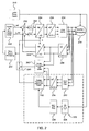
- Converters 254 and 256 convert the commands from signals for the quadrature and direct axis currents into commands for the individual phases (a, b, c). These commands are then fed into the inverter 258 (e.g., a pulse width modulation (PWM) inverter as shown) which provides the main stator power to motor/generator 230.
- PWM pulse width modulation
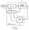
- the above referenced control and inverter system has shown specific elements such as a PID controllers and PWM inverter, those skilled in the art will appreciate that many variations of the controller/inverter configuration are known. Further, the present invention is not limited to a particular controller/inverter scheme because it serves as a true emulator for a position sensor. Therefore, the present invention serves to replace the position sensor signals in conventional systems and is designed to be compatible with control/ inverter schemes that use a position sensor for control.
Landscapes
- Engineering & Computer Science (AREA)
- Power Engineering (AREA)
- Control Of Eletrric Generators (AREA)
- Control Of Ac Motors In General (AREA)
- Control Of Electric Motors In General (AREA)
- Control Of Motors That Do Not Use Commutators (AREA)
Claims (8)
- Ein Positionssensoremulator (220) für Synchronmaschinen mit einem Schleifringläufer, wobei der Positionssensoremulator folgendes umfaßt:ein erstes Bandpaßfilter (222), das Phasenspannungssignale von einem Stator einer Synchronmaschine (230) herausfiltert, wobei die Synchronmaschine (230) simultan als Motor- und als Positionssensor verwendet wird; undeinen Konverter (224), der die gefilterten Phasenspannungen (a, b, c) in symmetrische Zweiphasen-Quadratursignale konvertiert;einen Gleichrichter (226), der Erreger (210)-Spannungssignale der Synchronmaschine (230) gleichrichtet; undein zweites Bandpaßfilter (228), das die gleichgerichteten Erregerspannungssignale filtert, um ein Referenzsignal zu erzeugen.
- Positionssensoremulator nach Anspruch 1, wobei das erste (222) und das zweite (228) Bandpaßfilter ein festes Durchlaßband aufweisen, wobei das feste Durchlaßband definiert ist als:

wobei f das Durchlaßband, Nph eine Anzahl von Phasen in einem Erregerstator, fex die Frequenz der Erregerspannung und wet die höchste elektrische Winkelgeschwindigkeit des Stators der Synchronmaschine ist. - Positionssensoremulator nach Anspruch 1, wobei das erste Bandpaßfilter (222) eine Mittenfrequenz aufweist, die eine Frequenzkomponente verfolgt, die Positionsinformationen enthält, wobei die Mittenfrequenz definiert ist als:

wobei f das Durchlaßband, Nph eine Anzahl von Phasen in einem Erregerstator, fex die Frequenz der Erregerspannung und We die elektrische Winkelgeschwindigkeit des Stators der Synchronmaschine ist. - Positionssensoremulator nach nach Anspruch 1, wobei die Zweiphasen-Quadratursignale und das Referenzsignal als Eingaben verwendet werden, um einen Drehmelder in einem Antriebssystem für die Synchronmaschine (230) zu emulieren.
- Verfahren zum Emulieren eines Positionssensors für eine Synchronmaschine mit einem Schleifringläufer, wobei das Verfahren die folgenden Schritte umfaßt:Bandpaßfiltern von Phasenspannungssignalen von einem Stator einer Synchronmaschine (230), wobei die Synchronmaschine (230) simultan als Motor und als Positionssensor verwendet wird,Konvertieren der gefilterten Phasenspannungen (a, b, c) in symmetrische Zweiphasen-Quadratursignale,Gleichrichten von Erreger(210)-Spannungssignalen der Synchronmaschine (230) undBandpaßfilterung der gleichgerichteten Erregerspannungssignale, um ein Referenzsignal zu erzeugen.
- Verfahren nach Anspruch 5, wobei die Bandpaßfilterung der Phasenspannungssignale (a, b, c) und der gleichgerichteten Erregerspannungssignale ein festes Durchlaßband aufweist und wobei das feste Durchlaßband definiert ist als:

wobei f das Durchlaßband, Nph eine Anzahl von Phasen in einem Erregerstator, fex die Frequenz der Erregerspannung und wet die höchste elektrische Winkelgeschwindigkeit des Stators der Synchronmaschine ist. - Verfahren nach Anspruch 5, wobei die Bandpaßfilterung der Phasenspannungssignale (a, b, c) und der gleichgerichteten Erregerspannungssignale eine Mittenfrequenz aufweist, die eine Frequenzkomponente verfolgt, die Positionsinformationen enthält, wobei die Mittenfrequenz definiert ist als:

wobei f das Durchlaßband, Nph eine Anzahl von Phasen in einem Erregerstator, fex die Frequenz der Erregerspannung und we die elektrische Winkelgeschwindigkeit des Stators der Synchronmaschine ist. - Verfahren nach Anspruch 5, wobei die Zweiphasen-Quadratursignale und das Referenzsignal als Eingaben verwendet werden, um einen Drehmelder in einem Antriebssystem für die Synchronmaschine zu emulieren.
Applications Claiming Priority (3)
| Application Number | Priority Date | Filing Date | Title |
|---|---|---|---|
| US10/244,496 US6809496B2 (en) | 2002-09-16 | 2002-09-16 | Position sensor emulator for a synchronous motor/generator |
| US244496 | 2002-09-16 | ||
| PCT/US2003/030806 WO2004025821A2 (en) | 2002-09-16 | 2003-09-15 | Position sensor emulator for a wound rotor synchronous motor/ generator |
Publications (2)
| Publication Number | Publication Date |
|---|---|
| EP1540810A2 EP1540810A2 (de) | 2005-06-15 |
| EP1540810B1 true EP1540810B1 (de) | 2006-12-13 |
Family
ID=31991905
Family Applications (1)
| Application Number | Title | Priority Date | Filing Date |
|---|---|---|---|
| EP03795712A Expired - Lifetime EP1540810B1 (de) | 2002-09-16 | 2003-09-15 | Positionsensoremulator für einen synchron-motor/generator mit einem gewickelten läufer |
Country Status (7)
| Country | Link |
|---|---|
| US (1) | US6809496B2 (de) |
| EP (1) | EP1540810B1 (de) |
| JP (1) | JP2005539473A (de) |
| AT (1) | ATE348442T1 (de) |
| AU (1) | AU2003277093A1 (de) |
| DE (1) | DE60310423T2 (de) |
| WO (1) | WO2004025821A2 (de) |
Families Citing this family (35)
| Publication number | Priority date | Publication date | Assignee | Title |
|---|---|---|---|---|
| US6950321B2 (en) * | 2003-09-24 | 2005-09-27 | General Motors Corporation | Active damping control for L-C output filters in three phase four-leg inverters |
| JP4113848B2 (ja) * | 2004-02-18 | 2008-07-09 | 三菱電機株式会社 | 電動発電機の制御装置 |
| US7045986B2 (en) * | 2004-02-20 | 2006-05-16 | Honeywell International Inc. | Position sensing method and apparatus for synchronous motor generator system |
| US7184927B2 (en) | 2004-03-26 | 2007-02-27 | Honeywell International Inc. | Adaptive position sensing method and apparatus for synchronous motor generator system |
| US7208908B2 (en) * | 2004-07-12 | 2007-04-24 | Honeywell International Inc. | Apparatus and method to control torque and voltage of an AC machine |
| US20060043923A1 (en) * | 2004-08-31 | 2006-03-02 | Baker Donal E | Performance enhancement for motor field oriented control system |
| US20070244683A1 (en) * | 2005-08-19 | 2007-10-18 | Honeywell International Inc. | Device simulating operation of a machine that functions as either a motor or a generator |
| US7339344B2 (en) * | 2005-08-25 | 2008-03-04 | International Rectifier Corporation | Self tuning method and apparatus for permanent magnet sensorless control |
| WO2007092466A2 (en) * | 2006-02-03 | 2007-08-16 | Bae Systems Land & Armaments L.P. | Nonlinear motor control techniques |
| US7132816B1 (en) * | 2006-02-20 | 2006-11-07 | Hamilton Sundstrand Corporation | Brushless wound field synchronous machine rotor position tracking with exciter stator current harmonic tracking |
| US7514806B2 (en) * | 2007-06-05 | 2009-04-07 | Honeywell International Inc. | Engine start system with quadrature AC excitation |
| US7571072B2 (en) * | 2007-07-02 | 2009-08-04 | Honeywell International Inc. | Energy based position and speed self-sensing method and apparatus for synchronous machine |
| EP2023479B1 (de) * | 2007-08-06 | 2014-04-16 | Baumüller Nürnberg Gmbh | System zur nahtlosen Geschwindigkeits- und/oder Lageermittlung einschließlich Stillstand bei einem Permanentmagnet-Läufer einer elektrischen Maschine |
| DK2104220T3 (da) * | 2008-03-19 | 2010-03-22 | Abb Schweiz Ag | Fremgangsmåde til drift af et omformerkredsløb samt indretning til gennemførelse af fremgangsmåden |
| GB2460724B (en) * | 2008-06-13 | 2011-04-13 | Ehsan Abdi Jalebi | Torque-sensing control system for a brushless doubly fed machine (BFDM) |
| FI121721B (fi) * | 2008-09-04 | 2011-03-15 | Abb Oy | Menetelmä ja järjestely moottorin pyörimisnopeuden määrittämiseen |
| GB0908112D0 (en) * | 2009-05-12 | 2009-06-24 | Peto Raymond J | Apparatus and method for determining speed of a motor, generator or alternator |
| ES2592178T3 (es) * | 2009-06-19 | 2016-11-28 | Vestas Wind Systems A/S | Método para determinar la posición del rotor de un generador eléctrico en una turbina eólica |
| US8975878B2 (en) * | 2010-12-23 | 2015-03-10 | Caterpillar Inc. | Switched reluctance generator integrated controls |
| DE102011007331A1 (de) * | 2011-04-13 | 2012-10-18 | Robert Bosch Gmbh | Verfahren zur Erfassung einer Drehung eines Rotors eines Generators |
| ES2811533T3 (es) | 2012-03-05 | 2021-03-12 | Novanta Corp | Método de estimación de fase y aparato para el mismo |
| US8866449B1 (en) * | 2013-06-10 | 2014-10-21 | Hamilton Sundstrand Corporation | Sensor PM electrical machines |
| CN105659491B (zh) * | 2013-10-22 | 2018-09-07 | 三菱电机株式会社 | 电动机控制装置 |
| US9362845B2 (en) * | 2013-12-23 | 2016-06-07 | Generac Power Systems, Inc. | Method of operating a single-phase generator in parallel with an inventor |
| US10027261B2 (en) * | 2014-03-05 | 2018-07-17 | Nidec Servo Corporation | Motor apparatus |
| US20150309096A1 (en) * | 2014-04-29 | 2015-10-29 | Lsis Co., Ltd. | Instantaneous power monitoring system for hvdc system |
| US10305356B2 (en) * | 2014-09-26 | 2019-05-28 | The Boeing Company | Synchronous machine with common motor/generator exciter stage |
| US9595903B2 (en) * | 2015-03-20 | 2017-03-14 | General Electric Company | Controller for motor |
| CN107294437A (zh) * | 2017-06-21 | 2017-10-24 | 苏州华铭威智能科技有限公司 | 一种无刷电机的启动方法和控制系统 |
| FR3073691B1 (fr) * | 2017-11-16 | 2020-07-17 | Renault S.A.S | Procede de commande d'une machine electrique synchrone |
| CN109656152B (zh) * | 2018-12-25 | 2021-10-15 | 西安翔迅科技有限责任公司 | 一种基于数字控制的发动机进/排气门作动器仿真组件系统及方法 |
| CN113612402A (zh) * | 2021-08-09 | 2021-11-05 | 山特电子(深圳)有限公司 | 一种三相逆变控制系统和控制方法 |
| CN116895203A (zh) * | 2023-05-30 | 2023-10-17 | 大唐水电科学技术研究院有限公司 | 发电机转子绕组rso特性仿真器及操作方法 |
| US12549115B2 (en) * | 2023-09-29 | 2026-02-10 | Stmicroelectronics International N.V. | Systems, apparatuses, and methods to perform startup step detection in an internal permanent magnet synchronous machine |
| CN117516365B (zh) * | 2023-11-03 | 2024-10-22 | 武汉光谷航天三江激光产业技术研究院有限公司 | 一种基于ansys仿真的角度传感器模糊标定方法及系统 |
Family Cites Families (23)
| Publication number | Priority date | Publication date | Assignee | Title |
|---|---|---|---|---|
| US3748555A (en) * | 1972-05-01 | 1973-07-24 | Westinghouse Electric Corp | Protective circuit for brushless synchronous motors |
| EP0228535A1 (de) * | 1985-12-04 | 1987-07-15 | Siemens Aktiengesellschaft | Verfahren und Vorrichtung zur Bestimmung des Flusswinkels einer Drehfeldmaschine bzw. zum Lageorientierten Betrieb der Maschine |
| US5182499A (en) * | 1990-10-25 | 1993-01-26 | Matsushita Electric Industrial Co., Ltd. | Sensorless brushless motor |
| US5430362A (en) | 1993-05-12 | 1995-07-04 | Sundstrand Corporation | Engine starting system utilizing multiple controlled acceleration rates |
| US5384527A (en) | 1993-05-12 | 1995-01-24 | Sundstrand Corporation | Rotor position detector with back EMF voltage estimation |
| US5495163A (en) | 1993-05-12 | 1996-02-27 | Sundstrand Corporation | Control for a brushless generator operable in generating and starting modes |
| US5493200A (en) | 1993-05-12 | 1996-02-20 | Sundstrand Corporation | Control for a brushless generator |
| US5363032A (en) | 1993-05-12 | 1994-11-08 | Sundstrand Corporation | Sensorless start of synchronous machine |
| US5581168A (en) * | 1993-05-12 | 1996-12-03 | Sundstrand Corporation | Starter/generator system with DC link current control |
| US5444349A (en) | 1993-05-12 | 1995-08-22 | Sundstrand Corporation | Starting control for an electromagnetic machine |
| US5495162A (en) | 1993-05-12 | 1996-02-27 | Sundstrand Corporation | Position-and-velocity sensorless control for starter generator electrical system using generator back-EMF voltage |
| US5428275A (en) | 1993-05-12 | 1995-06-27 | Sundstrand Corporation | Controlled starting method for a gas turbine engine |
| US5461293A (en) | 1993-05-12 | 1995-10-24 | Sundstrand Corporation | Rotor position detector |
| US5594322A (en) | 1993-05-12 | 1997-01-14 | Sundstrand Corporation | Starter/generator system with variable-frequency exciter control |
| JP3381408B2 (ja) * | 1993-10-26 | 2003-02-24 | トヨタ自動車株式会社 | 電気角検出装置およびこれを用いた同期モータの駆動装置 |
| FR2714234B1 (fr) * | 1993-12-16 | 1996-08-23 | Telemecanique | Système de contrôle d'alimentation d'un moteur asynchrone. |
| US5585709A (en) * | 1993-12-22 | 1996-12-17 | Wisconsin Alumni Research Foundation | Method and apparatus for transducerless position and velocity estimation in drives for AC machines |
| MY120887A (en) | 1995-06-08 | 2005-12-30 | Sony Corp | Rotation position detecting device and motor device. |
| US5920162A (en) | 1996-08-05 | 1999-07-06 | Sundstrand Corporation | Position control using variable exciter feed through |
| US6271720B1 (en) * | 1998-09-02 | 2001-08-07 | Linear Technology Corporation | Operational filter building block |
| US6081091A (en) * | 1999-03-08 | 2000-06-27 | Motorola, Inc. | Motor controller, integrated circuit, and method of controlling a motor |
| WO2001015311A1 (fr) * | 1999-08-20 | 2001-03-01 | Mitsubishi Denki Kabushiki Kaisha | Dispositif et procede de controle du moteur synchrone |
| KR100354775B1 (ko) * | 2000-03-25 | 2002-11-04 | 엘지전자 주식회사 | 동기 릴럭턴스 모터의 속도 제어장치 |
-
2002
- 2002-09-16 US US10/244,496 patent/US6809496B2/en not_active Expired - Lifetime
-
2003
- 2003-09-15 EP EP03795712A patent/EP1540810B1/de not_active Expired - Lifetime
- 2003-09-15 AU AU2003277093A patent/AU2003277093A1/en not_active Abandoned
- 2003-09-15 DE DE60310423T patent/DE60310423T2/de not_active Expired - Lifetime
- 2003-09-15 JP JP2004536636A patent/JP2005539473A/ja not_active Withdrawn
- 2003-09-15 AT AT03795712T patent/ATE348442T1/de not_active IP Right Cessation
- 2003-09-15 WO PCT/US2003/030806 patent/WO2004025821A2/en not_active Ceased
Also Published As
| Publication number | Publication date |
|---|---|
| DE60310423T2 (de) | 2007-10-11 |
| US6809496B2 (en) | 2004-10-26 |
| DE60310423D1 (de) | 2007-01-25 |
| US20040052217A1 (en) | 2004-03-18 |
| AU2003277093A8 (en) | 2004-04-30 |
| WO2004025821A2 (en) | 2004-03-25 |
| AU2003277093A1 (en) | 2004-04-30 |
| EP1540810A2 (de) | 2005-06-15 |
| JP2005539473A (ja) | 2005-12-22 |
| WO2004025821A3 (en) | 2004-07-15 |
| ATE348442T1 (de) | 2007-01-15 |
Similar Documents
| Publication | Publication Date | Title |
|---|---|---|
| US6809496B2 (en) | Position sensor emulator for a synchronous motor/generator | |
| US7045986B2 (en) | Position sensing method and apparatus for synchronous motor generator system | |
| EP1728315B1 (de) | Adaptives positionserfassungsverfahren und vorrichtung für ein synchronmotor-generatorsystem | |
| US5920162A (en) | Position control using variable exciter feed through | |
| US5747971A (en) | Position and velocity sensorless control for a motor generator system operated as a motor using exciter impedance | |
| US5594322A (en) | Starter/generator system with variable-frequency exciter control | |
| US5495163A (en) | Control for a brushless generator operable in generating and starting modes | |
| US5461293A (en) | Rotor position detector | |
| US5488286A (en) | Method and apparatus for starting a synchronous machine | |
| US7034497B2 (en) | Carrier injection sensorless control of aircraft variable frequency wound field synchronous starter/generators | |
| EP2840702B1 (de) | Systeme für Synchronmotoren mit Feldwicklung mit Rotorpositionserfassung im Stillstand beim Start für Kraftfahrzeuge und verbessertes Einschwingverhalten zur Erzeugung | |
| KR100795382B1 (ko) | 영구 자석 회전 머신을 무센서 방식으로 제어하는 시스템및 방법 | |
| US4937508A (en) | VSCF start system with precision voltage | |
| EP1774646B1 (de) | Vorrichtung und verfahren zur drehmoment- und spannungssteuerung einer wechselstrommaschine | |
| US6301136B1 (en) | Floating flame controller | |
| US4484126A (en) | Induction motor controller | |
| Das et al. | Observer-based stator-flux-oriented vector control of cycloconverter-fed synchronous motor drive | |
| US5006768A (en) | Synchronous motor control | |
| JP2005117756A (ja) | 直流電圧検出回路の故障診断装置およびモータ制御システム | |
| KR100289430B1 (ko) | 동기식 리럭턴스 모터의 속도제어 방법 및 장치 | |
| JPH10229687A (ja) | 誘導電動機の可変速制御装置 | |
| JP4448300B2 (ja) | 同期機の制御装置 | |
| EP0073839B1 (de) | Steuergerät für synchronmotor | |
| SU1332427A1 (ru) | Электропривод | |
| SU1138916A1 (ru) | Частотно-управл емый синхронный электропривод |
Legal Events
| Date | Code | Title | Description |
|---|---|---|---|
| PUAI | Public reference made under article 153(3) epc to a published international application that has entered the european phase |
Free format text: ORIGINAL CODE: 0009012 |
|
| 17P | Request for examination filed |
Effective date: 20050324 |
|
| AK | Designated contracting states |
Kind code of ref document: A2 Designated state(s): AT BE BG CH CY CZ DE DK EE ES FI FR GB GR HU IE IT LI LU MC NL PT RO SE SI SK TR |
|
| AX | Request for extension of the european patent |
Extension state: AL LT LV MK |
|
| DAX | Request for extension of the european patent (deleted) | ||
| GRAP | Despatch of communication of intention to grant a patent |
Free format text: ORIGINAL CODE: EPIDOSNIGR1 |
|
| RTI1 | Title (correction) |
Free format text: POSITION SENSOR EMULATOR FOR A SYNCHRONOUS MOTOR/ GENERATOR WITH A WOUND ROTOR |
|
| GRAS | Grant fee paid |
Free format text: ORIGINAL CODE: EPIDOSNIGR3 |
|
| GRAA | (expected) grant |
Free format text: ORIGINAL CODE: 0009210 |
|
| AK | Designated contracting states |
Kind code of ref document: B1 Designated state(s): AT BE BG CH CY CZ DE DK EE ES FI FR GB GR HU IE IT LI LU MC NL PT RO SE SI SK TR |
|
| PG25 | Lapsed in a contracting state [announced via postgrant information from national office to epo] |
Ref country code: IT Free format text: LAPSE BECAUSE OF FAILURE TO SUBMIT A TRANSLATION OF THE DESCRIPTION OR TO PAY THE FEE WITHIN THE PRESCRIBED TIME-LIMIT;WARNING: LAPSES OF ITALIAN PATENTS WITH EFFECTIVE DATE BEFORE 2007 MAY HAVE OCCURRED AT ANY TIME BEFORE 2007. THE CORRECT EFFECTIVE DATE MAY BE DIFFERENT FROM THE ONE RECORDED. Effective date: 20061213 Ref country code: FI Free format text: LAPSE BECAUSE OF FAILURE TO SUBMIT A TRANSLATION OF THE DESCRIPTION OR TO PAY THE FEE WITHIN THE PRESCRIBED TIME-LIMIT Effective date: 20061213 Ref country code: CH Free format text: LAPSE BECAUSE OF FAILURE TO SUBMIT A TRANSLATION OF THE DESCRIPTION OR TO PAY THE FEE WITHIN THE PRESCRIBED TIME-LIMIT Effective date: 20061213 Ref country code: DK Free format text: LAPSE BECAUSE OF FAILURE TO SUBMIT A TRANSLATION OF THE DESCRIPTION OR TO PAY THE FEE WITHIN THE PRESCRIBED TIME-LIMIT Effective date: 20061213 Ref country code: LI Free format text: LAPSE BECAUSE OF FAILURE TO SUBMIT A TRANSLATION OF THE DESCRIPTION OR TO PAY THE FEE WITHIN THE PRESCRIBED TIME-LIMIT Effective date: 20061213 Ref country code: SK Free format text: LAPSE BECAUSE OF FAILURE TO SUBMIT A TRANSLATION OF THE DESCRIPTION OR TO PAY THE FEE WITHIN THE PRESCRIBED TIME-LIMIT Effective date: 20061213 Ref country code: RO Free format text: LAPSE BECAUSE OF FAILURE TO SUBMIT A TRANSLATION OF THE DESCRIPTION OR TO PAY THE FEE WITHIN THE PRESCRIBED TIME-LIMIT Effective date: 20061213 Ref country code: BE Free format text: LAPSE BECAUSE OF FAILURE TO SUBMIT A TRANSLATION OF THE DESCRIPTION OR TO PAY THE FEE WITHIN THE PRESCRIBED TIME-LIMIT Effective date: 20061213 Ref country code: NL Free format text: LAPSE BECAUSE OF FAILURE TO SUBMIT A TRANSLATION OF THE DESCRIPTION OR TO PAY THE FEE WITHIN THE PRESCRIBED TIME-LIMIT Effective date: 20061213 Ref country code: AT Free format text: LAPSE BECAUSE OF FAILURE TO SUBMIT A TRANSLATION OF THE DESCRIPTION OR TO PAY THE FEE WITHIN THE PRESCRIBED TIME-LIMIT Effective date: 20061213 Ref country code: SI Free format text: LAPSE BECAUSE OF FAILURE TO SUBMIT A TRANSLATION OF THE DESCRIPTION OR TO PAY THE FEE WITHIN THE PRESCRIBED TIME-LIMIT Effective date: 20061213 Ref country code: CZ Free format text: LAPSE BECAUSE OF FAILURE TO SUBMIT A TRANSLATION OF THE DESCRIPTION OR TO PAY THE FEE WITHIN THE PRESCRIBED TIME-LIMIT Effective date: 20061213 |
|
| REG | Reference to a national code |
Ref country code: GB Ref legal event code: FG4D |
|
| REG | Reference to a national code |
Ref country code: CH Ref legal event code: EP |
|
| REG | Reference to a national code |
Ref country code: IE Ref legal event code: FG4D |
|
| REF | Corresponds to: |
Ref document number: 60310423 Country of ref document: DE Date of ref document: 20070125 Kind code of ref document: P |
|
| PG25 | Lapsed in a contracting state [announced via postgrant information from national office to epo] |
Ref country code: SE Free format text: LAPSE BECAUSE OF FAILURE TO SUBMIT A TRANSLATION OF THE DESCRIPTION OR TO PAY THE FEE WITHIN THE PRESCRIBED TIME-LIMIT Effective date: 20070313 Ref country code: BG Free format text: LAPSE BECAUSE OF FAILURE TO SUBMIT A TRANSLATION OF THE DESCRIPTION OR TO PAY THE FEE WITHIN THE PRESCRIBED TIME-LIMIT Effective date: 20070313 |
|
| PG25 | Lapsed in a contracting state [announced via postgrant information from national office to epo] |
Ref country code: ES Free format text: LAPSE BECAUSE OF FAILURE TO SUBMIT A TRANSLATION OF THE DESCRIPTION OR TO PAY THE FEE WITHIN THE PRESCRIBED TIME-LIMIT Effective date: 20070324 |
|
| PG25 | Lapsed in a contracting state [announced via postgrant information from national office to epo] |
Ref country code: PT Free format text: LAPSE BECAUSE OF FAILURE TO SUBMIT A TRANSLATION OF THE DESCRIPTION OR TO PAY THE FEE WITHIN THE PRESCRIBED TIME-LIMIT Effective date: 20070514 |
|
| ET | Fr: translation filed | ||
| NLV1 | Nl: lapsed or annulled due to failure to fulfill the requirements of art. 29p and 29m of the patents act | ||
| REG | Reference to a national code |
Ref country code: CH Ref legal event code: PL |
|
| PLBE | No opposition filed within time limit |
Free format text: ORIGINAL CODE: 0009261 |
|
| STAA | Information on the status of an ep patent application or granted ep patent |
Free format text: STATUS: NO OPPOSITION FILED WITHIN TIME LIMIT |
|
| 26N | No opposition filed |
Effective date: 20070914 |
|
| PG25 | Lapsed in a contracting state [announced via postgrant information from national office to epo] |
Ref country code: MC Free format text: LAPSE BECAUSE OF NON-PAYMENT OF DUE FEES Effective date: 20070930 Ref country code: GR Free format text: LAPSE BECAUSE OF FAILURE TO SUBMIT A TRANSLATION OF THE DESCRIPTION OR TO PAY THE FEE WITHIN THE PRESCRIBED TIME-LIMIT Effective date: 20070314 |
|
| PG25 | Lapsed in a contracting state [announced via postgrant information from national office to epo] |
Ref country code: IE Free format text: LAPSE BECAUSE OF NON-PAYMENT OF DUE FEES Effective date: 20070917 |
|
| PG25 | Lapsed in a contracting state [announced via postgrant information from national office to epo] |
Ref country code: EE Free format text: LAPSE BECAUSE OF FAILURE TO SUBMIT A TRANSLATION OF THE DESCRIPTION OR TO PAY THE FEE WITHIN THE PRESCRIBED TIME-LIMIT Effective date: 20061213 |
|
| PG25 | Lapsed in a contracting state [announced via postgrant information from national office to epo] |
Ref country code: CY Free format text: LAPSE BECAUSE OF FAILURE TO SUBMIT A TRANSLATION OF THE DESCRIPTION OR TO PAY THE FEE WITHIN THE PRESCRIBED TIME-LIMIT Effective date: 20061213 Ref country code: LU Free format text: LAPSE BECAUSE OF NON-PAYMENT OF DUE FEES Effective date: 20070915 |
|
| PG25 | Lapsed in a contracting state [announced via postgrant information from national office to epo] |
Ref country code: HU Free format text: LAPSE BECAUSE OF FAILURE TO SUBMIT A TRANSLATION OF THE DESCRIPTION OR TO PAY THE FEE WITHIN THE PRESCRIBED TIME-LIMIT Effective date: 20070614 Ref country code: TR Free format text: LAPSE BECAUSE OF FAILURE TO SUBMIT A TRANSLATION OF THE DESCRIPTION OR TO PAY THE FEE WITHIN THE PRESCRIBED TIME-LIMIT Effective date: 20061213 |
|
| REG | Reference to a national code |
Ref country code: FR Ref legal event code: PLFP Year of fee payment: 13 |
|
| REG | Reference to a national code |
Ref country code: FR Ref legal event code: PLFP Year of fee payment: 14 |
|
| REG | Reference to a national code |
Ref country code: FR Ref legal event code: PLFP Year of fee payment: 15 |
|
| REG | Reference to a national code |
Ref country code: FR Ref legal event code: PLFP Year of fee payment: 16 |
|
| PGFP | Annual fee paid to national office [announced via postgrant information from national office to epo] |
Ref country code: GB Payment date: 20220920 Year of fee payment: 20 Ref country code: DE Payment date: 20220927 Year of fee payment: 20 |
|
| PGFP | Annual fee paid to national office [announced via postgrant information from national office to epo] |
Ref country code: FR Payment date: 20220926 Year of fee payment: 20 |
|
| P01 | Opt-out of the competence of the unified patent court (upc) registered |
Effective date: 20230525 |
|
| REG | Reference to a national code |
Ref country code: DE Ref legal event code: R071 Ref document number: 60310423 Country of ref document: DE |
|
| REG | Reference to a national code |
Ref country code: GB Ref legal event code: PE20 Expiry date: 20230914 |
|
| PG25 | Lapsed in a contracting state [announced via postgrant information from national office to epo] |
Ref country code: GB Free format text: LAPSE BECAUSE OF EXPIRATION OF PROTECTION Effective date: 20230914 |