EP1540433B1 - System zur virtuellen prozessanbindung über remote desktop protocol (rdp) - Google Patents
System zur virtuellen prozessanbindung über remote desktop protocol (rdp) Download PDFInfo
- Publication number
- EP1540433B1 EP1540433B1 EP03747825A EP03747825A EP1540433B1 EP 1540433 B1 EP1540433 B1 EP 1540433B1 EP 03747825 A EP03747825 A EP 03747825A EP 03747825 A EP03747825 A EP 03747825A EP 1540433 B1 EP1540433 B1 EP 1540433B1
- Authority
- EP
- European Patent Office
- Prior art keywords
- client
- data
- server
- communication channel
- automation devices
- Prior art date
- Legal status (The legal status is an assumption and is not a legal conclusion. Google has not performed a legal analysis and makes no representation as to the accuracy of the status listed.)
- Expired - Lifetime
Links
- 238000004891 communication Methods 0.000 claims description 58
- 238000000034 method Methods 0.000 claims description 42
- 238000003745 diagnosis Methods 0.000 claims 2
- 230000002045 lasting effect Effects 0.000 claims 2
- 230000005540 biological transmission Effects 0.000 description 17
- 238000012544 monitoring process Methods 0.000 description 4
- 238000012546 transfer Methods 0.000 description 3
- 238000005516 engineering process Methods 0.000 description 2
- 230000005641 tunneling Effects 0.000 description 2
- 238000013501 data transformation Methods 0.000 description 1
- 230000000694 effects Effects 0.000 description 1
- 238000012423 maintenance Methods 0.000 description 1
- 238000004519 manufacturing process Methods 0.000 description 1
- 238000012806 monitoring device Methods 0.000 description 1
- 238000005457 optimization Methods 0.000 description 1
- 230000003068 static effect Effects 0.000 description 1
Images
Classifications
-
- H—ELECTRICITY
- H04—ELECTRIC COMMUNICATION TECHNIQUE
- H04L—TRANSMISSION OF DIGITAL INFORMATION, e.g. TELEGRAPHIC COMMUNICATION
- H04L67/00—Network arrangements or protocols for supporting network services or applications
- H04L67/01—Protocols
- H04L67/131—Protocols for games, networked simulations or virtual reality
-
- H—ELECTRICITY
- H04—ELECTRIC COMMUNICATION TECHNIQUE
- H04L—TRANSMISSION OF DIGITAL INFORMATION, e.g. TELEGRAPHIC COMMUNICATION
- H04L67/00—Network arrangements or protocols for supporting network services or applications
- H04L67/01—Protocols
- H04L67/08—Protocols specially adapted for terminal emulation, e.g. Telnet
Definitions
- the invention relates to a system for process interfacing in the automation environment for distributed engineering systems with a server for providing at least one application required for the engineering, at least one client for accessing process and / or configuration data supplying automation devices and to build an existing for any duration Online communication channel between the client and the server, the applications being usable online by the client. Furthermore, the invention relates to a method for process connection in the automation environment for distributed engineering systems and a server and a client.
- a method for monitoring and controlling a machine in which a communication channel is set up between the machine and a monitoring or diagnostic device with the aid of a mobile device, such as a mobile telephone, via which the monitoring device can read diagnostic information from the machine.
- a communication system in which a client in the form of a mobile device is connected to a host computer via an infrared link.
- the host computer and the client are each connected to automation devices in the form of control processors of a factory.
- the invention has for its object to provide a way to operate an installed on a server engineering system from different locations as well as variable and flexible to connect to any automation devices.
- This object is achieved for a system for process connection in the automation environment for distributed engineering systems with a server for providing at least one application required for the engineering, at least one client for accessing process and / or configuration data supplied automation devices and to build one for any duration existing online communication channel between the client and the server, the applications are used by the client online, solved in that the system first means for introducing data of the automation devices via the communication channel to the server and second means on the client for Connecting the applications to the automation devices, wherein the first means have a first interface to the communication channel and a second interface to the applications and - to communicate with the second means (7) via the communication channel (8), - for routing data further automation devices (5a), which are introduced via at least one further client (4a) and a second communication channel (8a) to the server (2) are provided to the client (4).
- the invention is based on the finding that the engineering systems used today for engineering in the automation environment are generally monolithic, ie they are installed on a central server and can only be operated there. In modern plants, which are characterized by ever-increasing complexity, heterogeneity and decentralization, it is advantageous if the engineering systems can be operated from different locations or locations, and from these locations to any process or configuration data can be accessed.
- a virtual process connection which takes place via an online communication channel, from the engineering system on a server to any automation devices that can be addressed via clients, built.
- the proposed system thus enables the operation of an engineering system including access to process and diagnostic data from anywhere within the system.
- the advantage here is especially the optimization of resource use on the system within the automation system.
- the clients used may be, for example, thin clients, since they do not have to run any applications themselves.
- the applications are rather installed on the server, via however, the client can be used remotely online and the required data is also available through the communication channel.
- An engineering can thus be carried out much more variable and flexible.
- the virtual process connection via the online data channel enables distributed engineering even in monolithic systems. The user only needs online access for data access and engineering. From the client, the system can then be operated. The engineering system itself does not have to be on the computer that the application uses.
- the online access to the automation devices is produced by so-called tunneling of communication data packets through the communication channel.
- the invention is characterized in that the first means are provided for introducing data of further automation devices via at least one further client via the communication channel to the server.
- This embodiment of the invention makes it possible to access from any client to automation devices which are connected to any other client within the system and to access the relevant data of these programmable controllers. For this purpose, a routing is performed on the server, so that a virtual peer-2-peer communication (direct communication) between the clients involved is made possible. Access and configuration options from one client system to another client system are thereby realized. At any point within the system, any process or diagnostic data is available that is stored elsewhere in the system.
- a further advantageous embodiment of the invention is characterized in that the client is designed as a programming device and / or as an operator panel and / or as a diagnostic device and / or as a browser and / or as a Windows CE device.
- the client is designed as a programming device and / or as an operator panel and / or as a diagnostic device and / or as a browser and / or as a Windows CE device.
- any devices present on a system which are generally already used today for monitoring and operating the system or the automation system can likewise be used in the proposed system according to the invention for operation.
- the corresponding control data or diagnostic data of the automation devices can be transmitted to the server via the communication system and are thus available to the engineering system on the server. The engineering itself can in turn be performed directly from the proposed clients.
- a further advantageous embodiment of the invention is characterized in that the server is designed as a terminal server for simultaneous use by one or more participants.
- the server or the proposed system is thus multi-user capable, and several users can work on engineering at the same time, for which they rely on process or diagnostic data have to resort within the system.
- a further advantageous embodiment of the invention is characterized in that the communication channel is designed as a Remote Desktop Protocol for transmitting data in real time via one and / or several separate virtual channels to one or more subscribers.
- RDP Remote Desktop Protocol
- Using the Remote Desktop Protocol (RDP) from Microsoft enables efficient and speedy sending of data packets over the communication channel between a client and the server, which significantly improves engineering and access to the process or configuration data.
- multiple data packets from multiple users of the system can be sent concurrently and independently over the communications channel without interference with negative consequences.
- the possibility of using several separate virtual channels for data transfer also means that the system is variable, flexible and freely scalable. Any number of users (limited by the capacities of the server) can simultaneously work on different clients within the system.
- a further advantageous embodiment of the invention is characterized in that the transmission of data in the communication channel via an intranet and / or an Internet is provided.
- the proposed system does not need to have its own infrastructures, such as special networks.
- the standard existing intranet or Internet can be used and the local standard protocols are also available for communication. This allows a cost-effective implementation of the system according to the invention without further expenses.
- a further advantageous embodiment of the invention is characterized in that the transmission of data from the client via Remote Desktop Protocol via wireless LAN (W-LAN) is provided.
- WLAN Remote Desktop Protocol
- Clients used within the system such as programmers, operator panels, diagnostic devices, or any browser, do not need to have a direct cable connection.
- the data transmission can rather be done wirelessly via a W-LAN network.
- the use of such networks has the advantage that a user does not have to be static in one place, but with his client only in a particular area or an environment in which he can transfer data via W-LAN, must stop.
- the use of the W-LAN thus allows a higher mobility of users or users on the system.
- a further advantageous embodiment of the invention is characterized in that the transmission of data via Remote Desktop Protocol is provided by further data sources present in the system via further standard protocols such as HTTP and / or FTP.
- Data which enter the system via other communication methods and networks can thus be used within of the system via the same communication channels. They are thus available to any user as well as the data of the automation devices which are connected to the clients. Universal access to all relevant data for the plant or the automation system is thus ensured.
- a further advantageous embodiment of the invention is characterized in that the system is intended for use over different locations.
- Distributed engineering by means of virtual access to process data and configuration data is thus not only possible at a single location within a plant, but also allows cross-location access to all relevant data.
- the proposed system is therefore ideal for the engineering of decentralized automation systems. It is especially advantageous that the clients used can be simple and have few resources.
- the applications are provided directly by the server.
- remote access or diagnostics is possible thanks to accessibility to configuration and process data across locations. Experts, who may not be on site, can access the relevant data from anywhere via the distributed system.
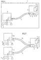
- FIG. 1 shows a schematic representation of an embodiment of the system 1 for virtual process interfacing in the automation environment for distributed engineering on monolithic systems.
- applications or applications 3 1..n required for the engineering are stored on a central server 2 within the system 1 and made available.
- Automation devices 5 present in the automation environment are connected to a client 4 via a data transmission device 9, for example a bus system. From the client can be accessed directly to the data of the programmable controllers 5.
- the communication between the terminal server 2 and the client 4 for online process connection is realized by means of the communication channel 8.
- a so-called Remote Desktop Protocol is used, which allows the sending of data packets via virtual channels online. Through the data channel 8 access to the online data of the automation devices is made possible by the terminal server 2.
- the terminal server means 6 for introducing data of the automation devices 5 via the communication channel 8.
- this is a software that runs on the terminal server 2, and ensures that the server 2 automatically to the automation device 5 of the corresponding client 4 is redirected.
- the software has two interfaces, firstly for communication with the communication channel 8 and secondly for the applications 3 1.n.
- Second means 7 on the client 4 provide for a connection of the applications 3 1..n to the respective automation devices . 5
- the peculiarity of in FIG. 1 exemplified system 1 is that process and diagnostic data from automation devices 5 through a data transmission channel 8 on a terminal server 2 at any time in real time available can be made.
- the client 4 establishes an online data connection via a so-called Remote Desktop Protocol.
- the means 7 for connecting the applications 3 1..n from the server 2 to the automation devices 5 are realized here as a software component in the form of a so-called online RDP proxy.
- the online RDP proxy ensures the connection of the engineering system to the respective automation devices 5.
- Further means 6 for introducing data from the automation devices 5 via the communication channel 8 are implemented on the server 2. They are realized in the form of software, a so-called online RDP DLL.
- Remote Desktop Protocol transmission involves the use of a standard protocol that allows real-time transmission of data from one application to multiple users across multiple virtual channels. In this case, the data is transmitted individually for each "session" (working time of the respective user).
- the data transmission via the protocol takes place here in so-called data packets, which are individually encrypted, packaged and sent with an address of the recipient.
- the specificity when sending via the Remote Desktop Protocol is that a so-called tunneling takes place.
- the users or the server 2 and the client 4 are not involved in the actual sending of the data.
- the data transformation rather takes place in the context of the RDP protocol.
- the client only needs to establish an online connection to the server.
- the online RDP DLL on the server 2 and the online RDP proxy on the client 4 are solely responsible for providing the data and making the correct address to which the data is to be sent.
- the advantage of such a data transmission via an online RDP standard protocol is above all that an existing infrastructure, such as the Internet, can be used for data transmission. A laying of cables or other data transmission devices within the system 1 is unnecessary. Thus, the data transmission can be realized in a cost effective manner.
- a transmission of process or diagnostic data in real time is possible.
- specific applications 3 1..n provided on a server 2 can be used by any clients 4 within the system 1. A user can thus, for example, use an engineering system directly on site on a programming device and at the same time all process data or diagnostic data of the automation devices 5 are available to him.
- the client used here can be a so-called thin client, which is for example exclusively a browser.
- the client always fetches the required application 3 i for the activity to be performed by the server 2.
- a user can work with an engineering system, such as a step 7, on site.
- FIG. 2 shows an exemplary embodiment of the system 1, in which is accessed by a client 4 to process data from automation devices 5a, which are connected via a data transmission system 9 to another client 4a.
- the data transmission takes place here via the communication channel 8 and the communication channel 8a.
- a second communication channel 8a is established between the terminal server 2 and the second client 4a.
- the data transfer then takes place from the client 4a via the terminal server 2 to the client 4.
- the online RDP DLL 6 on the server 2 thus carries out a routing, ie a forwarding of the corresponding data packets to the client 4 and the client 4a.
- a quasi p2p connection between the participating clients 4 and 4a is established.
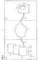
- FIG. 3 shows an exemplary embodiment of the system 1, wherein the process or diagnostic data via an Internet or intranet 11 are transmitted.
- the clients 4 1... N are connected to the Internet or intranet 11 by means of an online RDP protocol via which a communication channel 8 is established.
- the terminal server 2 also has the communication channel 8 via an Internet connection.
- the illustrated embodiment of the system 1 essentially consists of being able to access data, both process and diagnostic data within the system 1, independently of location via various locations (A, B, C) which may be far apart.
- A, B, C various locations which may be far apart.
- the use of the proposed system 1 is thus of great advantage.
- Engineering as well as information and maintenance can be done from different locations in system 1, since all data via the online RDP communication channels 8 and the Internet 11 are always available everywhere in real time.
- a virtual process connection of the participating units within the system 1 is thus always available.
- Distributed engineering is thus also possible in monolithic systems or applications that are prevalent today. It is also advantageous that the system 1 is freely scalable.
- New automation devices 5 can be connected to the system at any time via a simple client 4 i , for example, a thin clinet.
- a simple client 4 i for example, a thin clinet.
- the only requirement is an online access. This can even be realized today without laying cables over a W-Lan. If such a WLAN is present within a specific environment, the data can also be made available on mobile clients 4 1... N at any time in real time.
- the invention relates in summary to a system 1 and a method for online virtual process connection for distributed engineering systems in automation technology based on Remote Desktop Protocol (RDP).
- RDP Remote Desktop Protocol
- a communication channel 8 is set up by the RDP to a server 2 by any clients 4 within the system 1.
- Process and configuration data are tunneled via channel 8.
- a quasi-peer-to-peer communication between any clients 4 in the system 1 is made possible by routing on the server 2.
Landscapes
- Engineering & Computer Science (AREA)
- Computer Networks & Wireless Communication (AREA)
- Signal Processing (AREA)
- Computer And Data Communications (AREA)
- Testing And Monitoring For Control Systems (AREA)
- Multi Processors (AREA)
Description
- Die Erfindung betrifft ein System zur Prozessanbindung im Automatisierungsumfeld für verteilte Engineering-Systeme mit einem Server zur Bereitstellung mindestens einer für das Engineering benötigten Anwendung, mindestens einem Client zum Zugriff auf Prozess- und/oder Projektierungsdaten liefernde Automatisierungsgeräte und zum Aufbau eines für eine beliebige Dauer bestehenden Online-Kommunikationskanals zwischen dem Client und dem Server, wobei die Anwendungen vom Client online nutzbar sind. Des Weiteren betrifft die Erfindung ein Verfahren zur Prozessanbindung im Automatisierungsumfeld für verteilte Engineering-Systeme sowie einen Server und einen Client.
- Heutige Engineering-Systeme in der Automatisierungstechnik sind in der Regel sogenannte monolithische Systeme, die nicht die Möglichkeit eines verteilten Engineerings bzw. eines verteilten Projektierens bieten. Da Anlagen sowie Automatisierungssysteme jedoch immer komplexer und weitläufiger werden, wird der Zugriff auf Prozess- und Diagnosedaten sowie Projektierdaten für das Engineering von beliebiger Stelle innerhalb der Anlage bzw. des Automatisierungssystems aus gewünscht. Hierzu werden heutzutage sogenannte Terminalserverlösungen auf Basis des Transports von Bilddaten (Bitmaps) vom Server zum Client verwendet, wobei Tastatur und Mausaktionen vom Client zum Server übermittelt werden. Es ist jedoch nicht möglich, über ein zentrales Engineering-System auf beliebige Online-Daten, d.h. solche Daten, die auf der jeweiligen CPU eines in der Peripherie existierenden Clients, wie beispielsweise ein Operator Panel oder ein Programmiergerät, zuzugreifen. Ebenso sind Projektierungsdaten, die auf einem derartigen Client gespeichert sind, für das Engineering-System nicht direkt verfügbar.
- Aus der
US 2002/0114433 A1 ist ein Verfahren zur Überwachung und Steuerung einer Maschine bekannt, bei dem zwischen der Maschine und einem Überwachungs- bzw. Diagnosegerät mit Hilfe eines mobilen Gerätes, wie z.B. einem Mobiltelefon, ein Kommunikationskanal aufgebaut wird, über den das Überwachungsgerät Diagnoseinformationen aus der Maschine auslesen kann. - Aus der
US 6,067,477 A ist ein System zum Steuern und Überwachen technischer Prozesse bekannt, bei dem von verschiedenen Clients aus über einen Server auf verschiedene unternehmensweite Echtzeitanwendungen und -systeme zugegriffen werden kann. - Aus der
US 5,309,351 A ist ein Kommunikationssystem bekannt, bei dem ein Client in Form eines mobilen Gerätes über eine Infrarotverbindung mit einen Host Computer verbunden ist. Darüber hinaus sind der Host Computer sowie der Client jeweils an Automatisierungsgeräte in Form von Steuerungsprozessoren einer Fabrikanlage angebunden. - Der Erfindung liegt die Aufgabe zugrunde, eine Möglichkeit zu schaffen, ein auf einem Server installiertes Engineering-System von verschiedenen Standorten aus bedienen sowie variabel und flexibel an beliebige Automatisierungsgeräte anbinden zu können.
- Diese Aufgabe wird für ein System zur Prozessanbindung im Automatisierungsumfeld für verteilte Engineering-Systeme mit einem Server zur Bereitstellung mindestens einer für das Engineering benötigten Anwendung, mindestens einem Client zum Zugriff auf Prozess- und/oder Projektierungsdaten liefernde Automatisierungsgeräte und zum Aufbau eines für eine beliebige Dauer bestehenden Online-Kommunikationskanals zwischen dem Client und dem Server, wobei die Anwendungen vom Client online nutzbar sind, dadurch gelöst, dass das System erste Mittel zum Einschleusen von Daten der Automatisierungsgeräte über den Kommunikationskanal auf den Server und zweite Mittel auf dem Client zum Anbinden der Anwendungen an die Automatisierungsgeräte aufweist, wobei die ersten Mittel über eine erste Schnittstelle zum Kommunikationskanal und über eine zweite Schnittstelle zu den Anwendungen verfügen sowie - zur Kommunikation mit den zweiten Mitteln (7) über den Kommunikationskanal (8), - zum Routing von Daten weiterer Automatisierungsgeräte (5a), die über mindestens einen weiteren Client (4a) sowie einen zweiten Kommunikationskanal (8a) auf den Server (2) eingeschleust werden, zu dem Client (4) vorgesehen sind.
- Der Erfindung liegt die Erkenntnis zugrunde, dass die heutzutage für das Engineering im Automatisierungsumfeld verwendeten Engineering-Systeme in der Regel monolithisch sind, d.h. sie sind auf einem zentralen Server installiert und können nur dort bedient werden. Auf modernen Anlagen, die sich durch immer höhere Komplexität, Heterogenität und eine Dezentralisation auszeichnen, ist es jedoch von Vorteil, wenn die Engineering-Systeme von unterschiedlichen Orten bzw. Standorten aus bedient werden können, und von diesen Orten auf beliebige Prozess- bzw. Projektierdaten zugegriffen werden kann. Hierzu wird in der vorgeschlagenen Erfindung eine virtuelle Prozessanbindung, welche über einen Online-Kommunikationskanal erfolgt, vom Engineering-System auf einem Server zu beliebigen Automatisierungsgeräten, welche über Clients angesprochen werden können, aufgebaut. Das vorgeschlagene System ermöglicht somit die Bedienung eines Engineerungs-Systems inklusive Zugriff auf Prozess- sowie Diagnosedaten von einem beliebigen Ort innerhalb des Systems. Vorteilhaft ist hierbei vor allem die Optimierung des Ressourceneinsatzes auf der Anlage innerhalb des Automatisierungssystems. Bei den verwendeten Clients kann es sich beispielsweise um Thin Clients handeln, da auf ihnen selbst keine Applikationen laufen müssen. Die Applikationen werden vielmehr auf dem Server installiert, über den Client können sie aber von Ferne online genutzt werden und die benötigten Daten stehen durch den Kommunikationskanal ebenfalls zur Verfügung. Ein Engineering kann somit wesentlich variabler und flexibler durchgeführt werden. Die virtuelle Prozessanbindung über den Online-Datenkanal ermöglicht ein verteiltes Engineering auch in monolithischen Systemen. Der Anwender benötigt für den Datenzugang und das Engineering nur einen Online-Zugang. Vom Client aus kann das System dann bedient werden. Das Engineering-System selbst muss nicht auf dem Rechner liegen, den der Anwendung benutzt. Der Online-Zugang zu den Automatisierungsgeräten wird durch sogenanntes Tunneling von Kommunikationsdatenpaketen durch den Kommunikationskanal hergestellt.
- Die Erfindung ist dadurch gekennzeichnet, dass die ersten Mittel zum Einschleusen von Daten weiterer Automatisierungsgeräte über mindestens einen weiteren Client über den Kommunikationskanal auf den Server vorgesehen sind. Diese Ausbildung der Erfindung ermöglicht es, von einem beliebigen Client aus auf Automatisierungsgeräte, welche an einen anderen beliebigen Client innerhalb des Systems angeschlossen sind und auf die relevanten Daten dieser Automatisierungsgeräte zugreifen zu können. Hierzu wird auf dem Server ein Routing vorgenommen, so dass eine virtuelle peer-2-peer-Kommunikation (direkte Kommunikation) zwischen den beteiligten Clients ermöglicht wird. Zugriffs- und Konfigurationsmöglichkeiten von einem Clientsystem zu einem anderen Clientsystem werden dadurch realisiert. An jeder Stelle innerhalb des Systems sind somit beliebige Prozess- bzw. Diagnosedaten verfügbar, die an einer anderen Stelle innerhalb des Systems gespeichert sind bzw. entstehen.
- Eine weitere vorteilhafte Ausbildung der Erfindung ist dadurch gekennzeichnet, dass der Client als Programmiergerät und/oder als Operator Panel und/oder als Diagnosegerät und/ oder als Browser und/oder als Windows-Ce-Gerät ausgebildet ist. Vorteilhaft ist hierbei vor allem, dass beliebige, auf einer Anlage vorhandene Geräte, die generell zum Beobachten und Bedienen der Anlage bzw. des Automatisierungssystems heutzutage bereits verwendet werden, im vorgeschlagenen erfindungsgemäßen System zur Bedienung ebenfalls herangezogen werden können. Über ein herkömmliches Programmiergerät oder ein Operator Panel können beispielsweise die entsprechenden Steuerungsdaten bzw. Diagnosedaten der Automatisierungsgeräte an den Server über das Kommunikationssystem übertragen werden und stehen dem Engineering-System auf dem Server somit zur Verfügung. Das Engineering selbst kann wiederum direkt von den vorgeschlagenen Clients aus durchgeführt werden.
- Eine weitere vorteilhafte Ausbildung der Erfindung ist dadurch gekennzeichnet, dass der Server als Terminal-Server zur simultanen Nutzung durch ein und/oder mehrere Teilnehmer ausgebildet ist. Der Server bzw. das vorgeschlagene System ist also multiuserfähig, und es können gleichzeitig mehrere Benutzer Engineeringarbeiten, für die sie auf Prozess- bzw. Diagnosedaten zurückgreifen müssen, innerhalb des Systems vornehmen.
- Eine weitere vorteilhafte Ausbildung der Erfindung ist dadurch gekennzeichnet, dass der Kommunikationskanal als Remote Desktop Protocol zur Übertragung von Daten in Echtzeit über einen und/oder mehrere separate virtuelle Kanäle an einen und/oder mehrere Teilnehmer ausbildet ist. Die Nutzung des Remote Desktop Protocols (RDP) von Microsoft ermöglicht ein effizientes und zügiges Versenden von Datenpaketen über den Kommunikationskanal zwischen einem Client und dem Server, was das Engineering und den Zugriff auf die Prozess- bzw. Projektierungsdaten erheblich verbessert. Außerdem können mehrere Datenpakete von mehreren Benutzern des Systems gleichzeitig und unabhängig voneinander über den Kommunikationskanal versendet werden, ohne dass es zu Interaktionen mit negativen Konsequenzen kommt. Die Möglichkeit, mehrere separate virtuelle Kanäle für den Datentransfer zu nutzen bewirkt zudem, dass das System variabel, flexibel und frei skalierbar ist. Es können beliebig viele Benutzer (begrenzt durch die Kapazitäten des Servers) gleichzeitig innerhalb des Systems an unterschiedlichen Clients arbeiten.
- Eine weitere vorteilhafte Ausbildung der Erfindung ist dadurch gekennzeichnet, dass die Übertragung von Daten im Kommunikationskanal über ein Intranet und/oder ein Internet vorgesehen ist. Für das vorgeschlagene System müssen somit keine eigenen Infrastrukturen, wie speziellen Netzwerke aufgebaut werden. Das standardmäßig vorhandene Intranet bzw. Internet kann genutzt werden und die dortigen Standardprotokolle stehen für die Kommunikation ebenfalls zur Verfügung. Dies ermöglicht eine kostengünstige Umsetzung des erfindungsgemäßen Systems ohne weitere Aufwendungen.
- Eine weitere vorteilhafte Ausbildung der Erfindung ist dadurch gekennzeichnet, dass die Übertragung von Daten vom Client per Remote Desktop Protocol über Wireless LAN (W-LAN) vorgesehen ist. Die innerhalb des Systems verwendeten Clients wie beispielsweise Programmiergeräte, Operator Panels, Diagnosegeräte oder beliebige Browser müssen nicht direkt über einen Kabelanschluss verfügen. Die Datenübertragung kann vielmehr schnurlos über ein W-LAN Netz erfolgen. Die Nutzung solche Netze hat den Vorteil, dass ein Anwender sich nicht statisch an einem Ort aufhalten muss, sondern sich mit seinem Client nur in einem bestimmten Bereich bzw. einem Umfeld, in welchem er Daten mittels W-LAN übertragen kann, aufhalten muss. Die Nutzung des W-LAN ermöglicht somit eine höhere Mobilität der Benutzer bzw. Anwender auf der Anlage.
- Eine weitere vorteilhafte Ausbildung der Erfindung ist dadurch gekennzeichnet, dass die Übertragung von Daten per Remote Desktop Protocol von weiteren, im System vorhandenen Datenquellen über weitere Standard-Protokolle wie HTTP und/oder FTP vorgesehen ist. Daten, welche über andere Kommunikationsverfahren und Netze in das System gelangen, können somit innerhalb des Systems über die gleichen Kommunikationskanäle versendet werden. Sie stehen einem beliebigen Anwender somit ebenso zur Verfügung, wie die Daten der Automatisierungsgeräte, welche mit den Clients verbunden sind. Ein universeller Zugriff auf sämtliche relevanten Daten für die Anlage bzw. das Automatisierungssystem wird somit gewährleistet.
- Eine weitere vorteilhafte Ausbildung der Erfindung ist dadurch gekennzeichnet, dass das System zur Nutzung über verschiedene Standorte hinweg vorgesehen ist. Ein verteiltes Engineering mittels virtuellem Zugriff auf Prozessdaten und Projektierungsdaten ist somit nicht nur an einem Standort innerhalb einer Anlage möglich, es wird vielmehr auch ein standortübergreifender Zugriff auf sämtliche relevanten Daten möglich. Das vorgeschlagene System eignet sich somit hervorragend für das Engineering von dezentralen Automatisierungssystemen. Hierbei ist vor allem von Vorteil, dass die verwendeten Clients einfach sein können und über wenige Ressourcen verfügen müssen. Die Anwendungen werden direkt vom Server zur Verfügung gestellt. Außerdem wird durch eine standortübergreifende Zugriffsmöglichkeit auf Projektierungs- und Prozessdaten auch eine Fernwartung bzw. Diagnose möglich. Experten, die unter Umständen nicht direkt vor Ort sind, können über das verteilte System von beliebiger Stelle aus auf die relevanten Daten zugreifen.
- Im Folgenden wird die Erfindung anhand der in den Figuren dargestellten Ausführungsbeispiele näher beschrieben und erläutert. Es zeigen:
- FIG 1
- eine schematische Darstellung des Systems zur virtuellen Online-Prozessanbindung im Automatisierungsumfeld,
- FIG 2
- eine schematische Darstellung der Zugriffs- und Konfigurationsmöglichkeiten zwischen zwei Clients innerhalb des Systems,
- FIG 3
- eine schematische Darstellung der Kommunikation innerhalb des Systems über verschiedene Standorte mittels Intranet/Internet.
-
Figur 1 zeigt eine schematische Darstellung eines Ausführungsbeispiels des Systems 1 zur virtuellen Prozessanbindung im Automatisierungsumfeld für verteiltes Engineering auf monolithischen Systemen. Hierbei werden für das Engineering benötigte Anwendungen bzw. Applikationen 31..n auf einem zentralen Server 2 innerhalb des Systems 1 gespeichert und zur Verfügung gestellt. Im Automatisierungsumfeld vorhandene Automatisierungsgeräte 5 sind über eine Datenübertragungsvorrichtung 9, beispielsweise ein Bussystem, mit einem Client 4 verbunden. Vom Client kann direkt auf die Daten der Automatisierungsgeräte 5 zugegriffen werden. Die Kommunikation zwischen dem Terminalserver 2 und dem Client 4 zur Online-Prozessanbindung wird mit Hilfe des Kommunikationskanals 8 realisiert. Hierbei wird ein sogenanntes Remote Desktop Protocol verwendet, welches das Versenden von Datenpaketen über virtuelle Kanäle online ermöglicht. Durch den Datenkanal 8 wird Zugriff auf die Online-Daten der Automatisierungsgeräte durch den Terminalserver 2 ermöglicht. Hierzu befinden sich auf dem Terminalserver Mittel 6 zum Einschleusen von Daten der Automatisierungsgeräte 5 über den Kommunikationskanal 8. In der Regel handelt es sich hierbei um eine Software, die auf dem Terminalserver 2 läuft, und dafür sorgt, dass der Server 2 automatisch zu dem Automatisierungsgerät 5 des entsprechenden Client 4 umgeleitet wird. Die Software besitzt zwei Schnittstellen, erstens zur Kommunikation mit dem Kommunikationskanal 8 und zweitens mit den Applikationen 31..n. Zweite Mittel 7 auf dem Client 4 sorgen für eine Anbindung der Anwendungen 31..n an die jeweiligen Automatisierungsgeräte 5. - Die Besonderheit des in
Figur 1 beispielhaft dargestellten Systems 1 besteht darin, dass Prozess- und Diagnosedaten von Automatisierungsgeräten 5 durch einen Datenübertragungskanal 8 auf einem Terminalserver 2 jederzeit in Echtzeit verfügbar gemacht werden können. Hierzu wird vom Client 4 eine Online-Datenverbindung über ein sogenanntes Remote Desktop Protocol aufgebaut. Die Mittel 7 zum Anbinden der Anwendungen 31..n vom Server 2 an die Automatisierungsgeräte 5 sind hierbei als Softwarekomponente in Form einer sogenannten Online-RDP-Proxy realisiert. Die Online-RDP-Proxy sorgt für die Anbindung des Engineering-Systems an die jeweiligen Automatisierungsgeräte 5. Weitere Mittel 6 zum Einschleusen von Daten der Automatisierungsgeräte 5 über den Kommunikationskanal 8 sind auf dem Server 2 realisiert. Sie sind in Form einer Software, einer sogenannten Online-RDP-DLL realisiert. Diese Online-RDP-DLL findet den entsprechenden Online-RDP-Proxi und die Daten der Automatisierungsgeräte 5 werden dann über den Kommunikationskanal 8 übertragen. Bei der Übertragung mittels Remote Desktop Protocol handelt es sich um die Nutzung eines Standardprotokolls, welches die Echtzeitversendung von Daten einer Applikation an mehrere Nutzer über mehrere virtuelle Kanäle ermöglicht. Hierbei werden die Daten individuell für jede "session" (Arbeitsdauer des jeweiligen Nutzers) übertragen. Die Datenübertragung über das Protokoll erfolgt hierbei in sogenannten Datenpaketen, die einzeln verschlüsselt, verpackt und mit einer Adresse des Empfängers versendet werden. Die Spezifität beim Versenden über das Remote Desktop Protocol besteht darin, dass ein sogenanntes Tunneling erfolgt. Die Anwender bzw. der Server 2 und der Client 4 sind nicht in das eigentliche Versenden der Daten involviert. Die Datentransformation erfolgt vielmehr im Rahmen des RDP-Protokolls. Vom Client muss ausschließlich eine Online-Verbindung zum Server aufgebaut werden. Die Online-RDP-DLL auf dem Server 2 sowie die Online-RDP-Proxy auf dem Client 4 sind ausschließlich für die Bereitstellung der Daten und das Ausmachen der richtigen Adresse, an welche die Daten gesendet werden sollen, verantwortlich. Der Vorteil bei einer derartigen Datenübertragung über ein Online-RDP-Standardprotokoll besteht vor allem darin, dass eine vorhandene Infrastruktur, wie beispielsweise das Internet, für die Datenübertragung genutzt werden kann. Eine Verlegung von Kabeln oder anderen Datenübertragungsvorrichtungen innerhalb des Systems 1 erübrigt sich. Somit kann die Datenübertragung auf kostengünstige Weise realisiert werden. Außerdem ist eine Übertragung von Prozess- bzw. Diagnosedaten in Echtzeit möglich. Des Weiteren können spezifische Anwendungen 31..n, welche auf einem Server 2 zur Verfügung gestellt werden, von beliebigen Clients 4 innerhalb des Systems 1 genutzt werden. Ein Anwender kann somit beispielsweise auf einem Programmiergerät direkt vor Ort ein Engineering-System nutzen und ihm stehen gleichzeitig sämtliche Prozessdaten bzw. Diagnosedaten der Automatisierungsgeräte 5 zur Verfügung. Der verwendete Client kann hierbei ein sogenannter Thin Client sein, bei dem es sich beispielsweise ausschließlich um einen Browser handelt. Der Client holt sich jeweils die benötigte Applikation 3i für die auszuführende Tätigkeit vom Server 2. Vor Ort kann also beispielsweise von einem Benutzer mit einem Engineering-System, wie einem Step 7, gearbeitet werden. -
Figur 2 zeigt eine beispielhafte Ausbildung des Systems 1, bei dem von einem Client 4 auf Prozessdaten von Automatisierungsgeräten 5a zugegriffen wird, welche über ein Datenübertragungssystem 9 an einen weiteren Client 4a angeschlossen sind. Die Datenübertragung erfolgt hierbei über den Kommunikationskanal 8 sowie den Kommunikationskanal 8a. Durch die Mittel 6 zum Einschleusen von Daten der Automatisierungsgeräte 5 wird ein zweiter Kommunikationskanal 8a zwischen dem Terminalserver 2 und dem zweiten Client 4a aufgebaut. Die Datenübertragung erfolgt dann vom Client 4a über den Terminalserver 2 zum Client 4. Von der Online-RDP-DLL 6 auf dem Server 2 wird also ein Routing, d.h. eine Weiterleitung der entsprechenden Datenpakete an den Client 4 und vom Client 4a durchgeführt. Somit wird eine quasi p2p-Verbindung zwischen den beteiligten Clients 4 und 4a etabliert. - Vorteilhaft ist in dem erfindungsgemäßen Beispiel vor allem, dass von einem Benutzer auf einer Anlage über einen beliebigen Client 4 der Zugriff auf beliebige Prozessdaten, welche von weiteren Automatisierungsgeräten 5a auf die der Client 4 keinen direkten Zugriff hat, über die virtuelle Prozessanbindung mittels der Online-RDP-Datenübertragung über den Kommunikationskanal 8 ermöglicht wird. Sämtliche Daten sind somit an jedem Ort innerhalb des Systems 1 für einen Benutzer zur Verfügung bereit. Durch das System 1 wird ein ausgesprochen variables und flexibles Engineering für den Benutzer möglich. Sowohl Anwendungen als auch Prozessdaten stehen über die virtuelle Prozessanbindung an jeder Stelle innerhalb des Systems 1 zur Verfügung.
-
Figur 3 zeigt eine beispielhafte Ausbildung des Systems 1, wobei die Prozess- bzw. Diagnosedaten über ein Internet bzw. Intranet 11 übertragen werden. Hierzu sind die Clients 41...n mittels Online-RDP-Protokoll, über welches ein Kommunikationskanal 8 aufgebaut wird, an das Internet bzw. Intranet 11 angebunden. Der Terminalserver 2 verfügt ebenfalls über den Kommunikationskanal 8 über eine Internetanbindung. - Der Vorteil der in
Figur 3 dargestellten Ausbildung des Systems 1 besteht im wesentlichen darin, dass standortunabhängig über verschiedene Lokalitäten (A,B,C), die weit voneinander entfernt sein können, auf Daten, sowohl Prozess- als auch Diagnosedaten innerhalb des Systems 1 zugegriffen werden kann. Bei der heutzutage vorherrschenden heterogenen Struktur von Automatisierungssystemen in Prozess- und Produktionsanlagen ist die Nutzung des vorgeschlagenen Systems 1 somit von großem Vorteil. Ein Engineering sowie Information und Wartung kann von unterschiedlichen Orten im System 1 aus vorgenommen werden, da alle Daten über die Online-RDP-Kommunikationskanäle 8 und das Internet 11 jederzeit überall in Echtzeit zur Verfügung stehen. Eine virtuelle Prozessanbindung der beteiligten Einheiten innerhalb des Systems 1 ist somit jederzeit gegeben. Ein verteiltes Engineering wird hierdurch auch in heute vorherrschenden monolithischen Systemen bzw. Anwendungen möglich. Vorteilhaft ist hierbei auch, dass das System 1 frei skalierbar ist. Neue Automatisierungsgeräte 5 können jederzeit über einen einfachen Client 4i, beispielsweise einen Thin clinet an das System angeschlossen werden. Die einzige Voraussetzung ist ein Online-Zugang. Dieser kann heutzutage sogar ohne Verlegung von Kabeln über ein W-Lan realisiert werden. Ist so ein W-Lan innerhalb eines bestimmten Umfeldes vorhanden, so können die Daten auch jederzeit in Echtzeit auf mobilen Clients 41 ...n zur Verfügung gestellt werden. - Die Erfindung betrifft zusammenfassend ein System 1 und ein verfahren zur virtuellen Online-Prozessanbindung für verteilte Engineering-Systeme in der Automatisierungstechnik auf der Basis von Remote Desktop Protocol (RDP). Über einen Online Zugang wird von beliebigen Clients 4 innerhalb des Systems 1 ein Kommunikationskanal 8 über das RDP zu einem Server 2 aufgebaut. Prozess- und Projektierungsdaten werden über den Kanal 8 getunnelt. Eine quasi peer-to-peer-Kommunikation zwischen beliebigen Clients 4 im System 1 wird durch routing auf dem Server 2 ermöglicht.
Claims (17)
- System (1) zur Prozessanbindung im Automatisierungsumfeld für verteilte Engineering-Systeme mit- einem Server (2) zur Bereitstellung mindestens einer für das Engineering benötigten Anwendung (31..n),- mindestens einem Client (4) zumgekennzeichnet durch- Zugriff auf Prozess- und/oder Projektierungsdaten liefernde Automatisierungsgeräte (5) und- zum Aufbau eines für eine beliebige Dauer bestehenden Online-Kommunikationskanals (8) zwischen dem Client (4) und dem Server (2), wobei die Anwendungen (31..n) vom Client (4) online nutzbar sind,- erste Mittel (6) zum Einschleusen von Daten der Automatisierungsgeräte (5) über den Kommunikationskanal (8) auf den Server (2) und- zweite Mittel (7) auf dem Client (4) zum Anbinden der Anwendungen (31..n) an die Automatisierungsgeräte (5),- wobei die ersten Mittel (6)- über eine erste Schnittstelle (12) zum Kommunikationskanal (8) und- über eine zweite Schnittstelle (13) zu den Anwendungen (31..n) verfügen sowie - zur Kommunikation mit den zweiten Mitteln (7) über den Kommunikationskanal (8), - zum Routing von Daten weiterer Automatisierungsgeräte (5a), die über mindestens einen weiteren Client (4a) sowie einen zweiten Kommunikationskanal (8a) auf den Server (2) eingeschleust werden, zu dem Client (4) vorgesehen sind.
- System nach Anspruch 1,
dadurch gekennzeichnet,
dass der Client (4) als Programmiergerät und/oder als Operator Panel und/oder als Diagnosegerät und/oder als Browser und/oder als Windows-CE-Gerät ausgebildet ist. - System nach einem der vorhergehenden Ansprüche,
dadurch gekennzeichnet,
dass der Server (2) als Terminal-Server zur simultanen Nutzung durch ein und/oder mehrere Teilnehmer ausgebildet ist. - System nach einem der vorhergehenden Ansprüche,
dadurch gekennzeichnet,
dass der Kommunikationskanal (8) als Remote Desktop Protocol zur Übertragung von Daten in Echtzeit über einen und/oder mehrere separate virtuelle Kanäle an einen und/oder mehrere Teilnehmer ausgebildet ist. - System nach einem der vorhergehenden Ansprüche,
dadurch gekennzeichnet,
dass die Übertragung von Daten im Kommunikationskanal (8) über ein Intranet und/oder ein Internet vorgesehen ist. - System nach einem der vorhergehenden Ansprüche,
dadurch gekennzeichnet,
dass die Übertragung von Daten vom Client (4) per Remote Desktop Protocol über ein Wireless LAN vorgesehen ist. - System nach einem der vorhergehenden Ansprüche,
dadurch gekennzeichnet,
dass die Übertragung von Daten per Remote Desktop Protocol von weiteren, im System (1) vorhandenen Daten-Quellen über weitere Standard-Protokolle wie HTTP und/oder FTP vorgesehen ist. - System nach einem der vorhergehenden Ansprüche,
dadurch gekennzeichnet,
dass das System (1) zur Nutzung über verschiedene Standorte (A, B) hinweg vorgesehen ist. - Verfahren zur Prozessanbindung im Automatisierungsumfeld für verteilte Engineering-Systeme, bei dem- mindestens eine für das Engineering benötigten Anwendung (31..n) von einem Server (2) bereitgestellt wird,- auf Prozess- und/oder Projektierungsdaten liefernde Automatisierungsgeräte (5) über mindestens einen Client (4) zugegriffen wird und- ein für eine beliebige Dauer bestehender Online-Kommunikationskanal (8) zwischen dem Client (4) und dem Server (2) aufgebaut wird, wobei die Anwendungen (31..n) vom Client (4) online genutzt werden,dadurch gekennzeichnet,- dass die Daten der Automatisierungsgeräte (5) über den Kommunikationskanal (8) auf den Server (2) eingeschleust werden,- dass die Anwendungen (31..n) an die Automatisierungsgeräte (5) angebunden werden und- dass über erste Mittel (6) mit- einer ersten Schnittstelle (12) zum Kommunikationskanal (8) und- einer zweiten Schnittstelle (13) zu den Anwendungen (31..n)mit zweiten Mitteln (7) auf dem Client (4) über den Kommunikationskanal (8) kommuniziert wird und- dass Daten weiterer Automatisierungsgeräte (5a) über mindestens einen weiteren Client (4a) sowie über einen zweiten Kommunikationskanal (8a) durch die ersten Mittel (6) auf den Server (2) eingeschleust und mittels Routing vom dem Server an den Client (4) übertragen werden.
- Verfahren nach Anspruch 9,
dadurch gekennzeichnet,
dass ein Programmiergerät und/oder Operator Panel und/oder Diagnosegerät und/oder Browser und/oder Windows-CE-Gerät als Client (4) verwendet wird. - Verfahren nach einem der Ansprüche 9 oder 10,
dadurch gekennzeichnet,
dass ein und/oder mehrere Teilnehmer den Server (2) simultan nutzen können. - Verfahren nach einem der Ansprüche 9 bis 11,
dadurch gekennzeichnet,
dass als Kommunikationskanal (8) ein Remote Desktop Protocol zur Übertragung von Daten in Echtzeit über einen und/oder mehrere separate virtuelle Kanäle an einen und/oder mehrere Teilnehmer verwendet wird. - Verfahren nach einem der Ansprüche 9 bis 12,
dadurch gekennzeichnet,
dass Daten im Kommunikationskanal (8) über ein Intranet und/oder ein Internet übertragen werden. - Verfahren nach einem der Ansprüche 9 bis 13,
dadurch gekennzeichnet,
dass Daten vom Client (4) per Remote Desktop Protocol über ein Wireless LAN übertragen werden. - Verfahren nach einem der Ansprüche 9 bis 14,
dadurch gekennzeichnet,
dass Daten per Remote Desktop Protocol von weiteren, im System (1) vorhandenen Daten-Quellen über weitere Standard-Protokolle wie http und/oder FTP übertragen werden. - Verfahren nach einem der Ansprüche 9 bis 15,
dadurch gekennzeichnet,
dass das System (1) über verschiedene Standorte (A, B) hinweg genutzt wird. - Server zur Bereitstellung mindestens einer für ein Engineering benötigten Anwendung (31..n), wobei die Anwendungen (31..n) von einem Client (4) online nutzbar sind, mit- Mitteln (6) zum Einschleusen von Daten von Automatisierungsgeräten (5) über einen Kommunikationskanal (8) zwischen dem Client (4) und dem Server (2), wobei die Mittel (6)- über eine erste Schnittstelle (12) zum Kommunikationskanal (8) und- - über eine zweite Schnittstelle (13) zu den Anwendungen (31..n) verfügen sowie- zum Routing von Daten weiterer Automatisierungsgeräte (5a), die über mindestens einen weiteren Client (4a) sowie einen zweiten Kommunikationskanal (8a) auf den Server (2) eingeschleust werden, zu dem Client (4) vorgesehen sind.
Applications Claiming Priority (3)
| Application Number | Priority Date | Filing Date | Title |
|---|---|---|---|
| DE10242919A DE10242919A1 (de) | 2002-09-16 | 2002-09-16 | System zur virtuellen Prozessanbindung über Remote Desktop Protocol (RDP) |
| DE10242919 | 2002-09-16 | ||
| PCT/DE2003/002888 WO2004027598A2 (de) | 2002-09-16 | 2003-09-01 | System zur virtuellen prozessanbindung über remote desktop protocol (rdp) |
Publications (2)
| Publication Number | Publication Date |
|---|---|
| EP1540433A2 EP1540433A2 (de) | 2005-06-15 |
| EP1540433B1 true EP1540433B1 (de) | 2008-04-23 |
Family
ID=31896040
Family Applications (1)
| Application Number | Title | Priority Date | Filing Date |
|---|---|---|---|
| EP03747825A Expired - Lifetime EP1540433B1 (de) | 2002-09-16 | 2003-09-01 | System zur virtuellen prozessanbindung über remote desktop protocol (rdp) |
Country Status (4)
| Country | Link |
|---|---|
| US (1) | US20060142878A1 (de) |
| EP (1) | EP1540433B1 (de) |
| DE (2) | DE10242919A1 (de) |
| WO (1) | WO2004027598A2 (de) |
Families Citing this family (46)
| Publication number | Priority date | Publication date | Assignee | Title |
|---|---|---|---|---|
| US7978716B2 (en) | 2003-11-24 | 2011-07-12 | Citrix Systems, Inc. | Systems and methods for providing a VPN solution |
| US8739274B2 (en) | 2004-06-30 | 2014-05-27 | Citrix Systems, Inc. | Method and device for performing integrated caching in a data communication network |
| US8495305B2 (en) | 2004-06-30 | 2013-07-23 | Citrix Systems, Inc. | Method and device for performing caching of dynamically generated objects in a data communication network |
| US7757074B2 (en) | 2004-06-30 | 2010-07-13 | Citrix Application Networking, Llc | System and method for establishing a virtual private network |
| KR20070045282A (ko) | 2004-07-23 | 2007-05-02 | 사이트릭스 시스템스, 인크. | 네트워크 노드 간의 통신을 최적화하기 위한 시스템 및방법 |
| CA2572401A1 (en) | 2004-07-23 | 2006-02-02 | Citrix Systems, Inc. | A method and systems for securing remote access to private networks |
| US8700695B2 (en) | 2004-12-30 | 2014-04-15 | Citrix Systems, Inc. | Systems and methods for providing client-side accelerated access to remote applications via TCP pooling |
| US8706877B2 (en) | 2004-12-30 | 2014-04-22 | Citrix Systems, Inc. | Systems and methods for providing client-side dynamic redirection to bypass an intermediary |
| US8954595B2 (en) | 2004-12-30 | 2015-02-10 | Citrix Systems, Inc. | Systems and methods for providing client-side accelerated access to remote applications via TCP buffering |
| US7810089B2 (en) | 2004-12-30 | 2010-10-05 | Citrix Systems, Inc. | Systems and methods for automatic installation and execution of a client-side acceleration program |
| US8549149B2 (en) | 2004-12-30 | 2013-10-01 | Citrix Systems, Inc. | Systems and methods for providing client-side accelerated access to remote applications via TCP multiplexing |
| US8255456B2 (en) | 2005-12-30 | 2012-08-28 | Citrix Systems, Inc. | System and method for performing flash caching of dynamically generated objects in a data communication network |
| US8743019B1 (en) | 2005-05-17 | 2014-06-03 | Nvidia Corporation | System and method for abstracting computer displays across a host-client network |
| US7676549B2 (en) * | 2005-05-27 | 2010-03-09 | Microsoft Corporation | Techniques for providing accessibility options in remote terminal sessions |
| US8272045B2 (en) * | 2005-12-15 | 2012-09-18 | Barclays Capital Inc. | System and method for secure remote desktop access |
| US7921184B2 (en) | 2005-12-30 | 2011-04-05 | Citrix Systems, Inc. | System and method for performing flash crowd caching of dynamically generated objects in a data communication network |
| US8301839B2 (en) | 2005-12-30 | 2012-10-30 | Citrix Systems, Inc. | System and method for performing granular invalidation of cached dynamically generated objects in a data communication network |
| US20100169229A1 (en) * | 2006-02-09 | 2010-07-01 | Jae Chun Lee | Business Processing System Using Remote PC Control System of Both Direction |
| US7548547B2 (en) | 2006-03-31 | 2009-06-16 | Microsoft Corporation | Controlling the transfer of terminal server data |
| US9195428B2 (en) | 2006-04-05 | 2015-11-24 | Nvidia Corporation | Method and system for displaying data from auxiliary display subsystem of a notebook on a main display of the notebook |
| US8775704B2 (en) | 2006-04-05 | 2014-07-08 | Nvidia Corporation | Method and system for communication between a secondary processor and an auxiliary display subsystem of a notebook |
| US8127286B2 (en) * | 2007-02-16 | 2012-02-28 | Microsoft Corporation | MSI enhancement to update RDP files |
| US7664993B2 (en) | 2007-02-27 | 2010-02-16 | Microsoft Corporation | Automation of testing in remote sessions |
| US8201218B2 (en) * | 2007-02-28 | 2012-06-12 | Microsoft Corporation | Strategies for securely applying connection policies via a gateway |
| US8140610B2 (en) * | 2007-05-31 | 2012-03-20 | Microsoft Corporation | Bitmap-based display remoting |
| US20080313545A1 (en) * | 2007-06-13 | 2008-12-18 | Microsoft Corporation | Systems and methods for providing desktop or application remoting to a web browser |
| US20090006537A1 (en) * | 2007-06-29 | 2009-01-01 | Microsoft Corporation | Virtual Desktop Integration with Terminal Services |
| US8789151B2 (en) * | 2008-01-09 | 2014-07-22 | Microsoft Corporation | Remote device communication platform |
| US8898321B2 (en) * | 2008-01-09 | 2014-11-25 | Microsoft Corporation | Remote device communication platform user interface |
| US8683062B2 (en) | 2008-02-28 | 2014-03-25 | Microsoft Corporation | Centralized publishing of network resources |
| US8161160B2 (en) * | 2008-02-28 | 2012-04-17 | Microsoft Corporation | XML-based web feed for web access of remote resources |
| US8176434B2 (en) * | 2008-05-12 | 2012-05-08 | Microsoft Corporation | Virtual desktop view scrolling |
| US8612862B2 (en) * | 2008-06-27 | 2013-12-17 | Microsoft Corporation | Integrated client for access to remote resources |
| EP2146272A1 (de) * | 2008-07-16 | 2010-01-20 | Pepperl + Fuchs GmbH | Umsetzen einer Remote Desktop Protocol Session und deren Darstellung auf mehreren Bildschirmen |
| US8736617B2 (en) | 2008-08-04 | 2014-05-27 | Nvidia Corporation | Hybrid graphic display |
| US8645559B2 (en) * | 2008-09-22 | 2014-02-04 | Microsoft Corporation | Redirection of multiple remote devices |
| US8799425B2 (en) | 2008-11-24 | 2014-08-05 | Nvidia Corporation | Configuring display properties of display units on remote systems |
| WO2010092585A1 (en) * | 2009-02-16 | 2010-08-19 | Communitake Technologies Ltd. | A system, a method and a computer program product for automated remote control |
| US9111325B2 (en) | 2009-12-31 | 2015-08-18 | Nvidia Corporation | Shared buffer techniques for heterogeneous hybrid graphics |
| US8780122B2 (en) | 2009-09-16 | 2014-07-15 | Nvidia Corporation | Techniques for transferring graphics data from system memory to a discrete GPU |
| US8463918B2 (en) | 2010-01-22 | 2013-06-11 | Microsoft Corporation | Loss tolerant protocol for remoting desktop graphics |
| US9137338B2 (en) * | 2010-01-22 | 2015-09-15 | Microsoft Technology Licensing, Llc | Multi-link remote protocol |
| US20110265009A1 (en) * | 2010-04-27 | 2011-10-27 | Microsoft Corporation | Terminal services view toolbox |
| WO2013158142A1 (en) * | 2012-04-16 | 2013-10-24 | Hewlett-Packard Development Company, L.P. | Secure network data |
| CN106161368B (zh) | 2015-04-07 | 2020-04-14 | 阿里巴巴集团控股有限公司 | 一种用于对云应用进行远程访问的方法、装置及系统 |
| JP2019036082A (ja) * | 2017-08-14 | 2019-03-07 | アズビル株式会社 | ビル管理システム、ビル管理方法、エンジニアリング装置、および、エンジニアリング用プログラム |
Family Cites Families (31)
| Publication number | Priority date | Publication date | Assignee | Title |
|---|---|---|---|---|
| US5309351A (en) * | 1988-10-27 | 1994-05-03 | Texas Instruments Incorporated | Communications, information, maintenance diagnostic and training system |
| US6094600A (en) * | 1996-02-06 | 2000-07-25 | Fisher-Rosemount Systems, Inc. | System and method for managing a transaction database of records of changes to field device configurations |
| EP0825506B1 (de) * | 1996-08-20 | 2013-03-06 | Invensys Systems, Inc. | Verfahren und Gerät zur Fernprozesssteuerung |
| US6445969B1 (en) * | 1997-01-27 | 2002-09-03 | Circuit Image Systems | Statistical process control integration systems and methods for monitoring manufacturing processes |
| US6067477A (en) * | 1998-01-15 | 2000-05-23 | Eutech Cybernetics Pte Ltd. | Method and apparatus for the creation of personalized supervisory and control data acquisition systems for the management and integration of real-time enterprise-wide applications and systems |
| US6463459B1 (en) * | 1999-01-22 | 2002-10-08 | Wall Data Incorporated | System and method for executing commands associated with specific virtual desktop |
| US7047180B1 (en) * | 1999-04-30 | 2006-05-16 | Autodesk, Inc. | Method and apparatus for providing access to drawing information |
| US6788980B1 (en) * | 1999-06-11 | 2004-09-07 | Invensys Systems, Inc. | Methods and apparatus for control using control devices that provide a virtual machine environment and that communicate via an IP network |
| US7330875B1 (en) * | 1999-06-15 | 2008-02-12 | Microsoft Corporation | System and method for recording a presentation for on-demand viewing over a computer network |
| US6499054B1 (en) * | 1999-12-02 | 2002-12-24 | Senvid, Inc. | Control and observation of physical devices, equipment and processes by multiple users over computer networks |
| US6917845B2 (en) * | 2000-03-10 | 2005-07-12 | Smiths Detection-Pasadena, Inc. | Method for monitoring environmental condition using a mathematical model |
| US6981041B2 (en) * | 2000-04-13 | 2005-12-27 | Aep Networks, Inc. | Apparatus and accompanying methods for providing, through a centralized server site, an integrated virtual office environment, remotely accessible via a network-connected web browser, with remote network monitoring and management capabilities |
| US20030061323A1 (en) * | 2000-06-13 | 2003-03-27 | East Kenneth H. | Hierarchical system and method for centralized management of thin clients |
| US6499001B1 (en) * | 2000-06-20 | 2002-12-24 | Lsi Logic Corporation | Engineering database feedback system |
| US6799198B1 (en) * | 2000-06-23 | 2004-09-28 | Nortel Networks Limited | Method and apparatus for providing user specific web-based help in a distributed system environment |
| US7024497B1 (en) * | 2000-09-07 | 2006-04-04 | Adaptec, Inc. | Methods for accessing remotely located devices |
| DE10065674A1 (de) * | 2000-12-29 | 2002-07-04 | Bsh Bosch Siemens Hausgeraete | Verfahren und Vorrichtung zur Steuerung von Hausgeräten und Steuerungssystem |
| JP2002244724A (ja) * | 2001-02-20 | 2002-08-30 | Honda Motor Co Ltd | 機械の遠隔監視装置および管理方法 |
| JP4160399B2 (ja) * | 2001-03-01 | 2008-10-01 | フィッシャー−ローズマウント システムズ, インコーポレイテッド | プロセスプラント内の指標の作成と表示 |
| US20020133634A1 (en) * | 2001-03-19 | 2002-09-19 | Jurgen Bieber | Thin client solutions with HMI systems |
| US20030061349A1 (en) * | 2001-09-24 | 2003-03-27 | George Lo | Method and system for collaboratively developing programming code for programmable controllers |
| US7346405B2 (en) * | 2001-12-04 | 2008-03-18 | Connected Energy Corp. | Interface for remote monitoring and control of industrial machines |
| US7313590B2 (en) * | 2001-12-12 | 2007-12-25 | Rich Media Club, Llc | Method and system for file server direct connection |
| US20040002950A1 (en) * | 2002-04-15 | 2004-01-01 | Brennan Sean F. | Methods and apparatus for process, factory-floor, environmental, computer aided manufacturing-based or other control system using hierarchically enumerated data set |
| US20040010560A1 (en) * | 2002-07-10 | 2004-01-15 | Sandage David A. | Method and apparatus to transmit infrared signals generated from a computer application using a remote device |
| US6957113B1 (en) * | 2002-09-06 | 2005-10-18 | National Semiconductor Corporation | Systems for allocating multi-function resources in a process system and methods of operating the same |
| US7376472B2 (en) * | 2002-09-11 | 2008-05-20 | Fisher-Rosemount Systems, Inc. | Integrated model predictive control and optimization within a process control system |
| US7164956B2 (en) * | 2003-06-30 | 2007-01-16 | General Electric Company | Remote operation management system |
| US7313605B2 (en) * | 2003-07-03 | 2007-12-25 | At&T Corp. | Externally controlled reachability in virtual private networks |
| JP2007536634A (ja) * | 2004-05-04 | 2007-12-13 | フィッシャー−ローズマウント・システムズ・インコーポレーテッド | プロセス制御システムのためのサービス指向型アーキテクチャ |
| EP1852776A1 (de) * | 2006-05-04 | 2007-11-07 | Siemens Aktiengesellschaft | Verfahren zum Betrieb eines Automatisierungsgerätes zusammen mit seiner Beschreibung |
-
2002
- 2002-09-16 DE DE10242919A patent/DE10242919A1/de not_active Ceased
-
2003
- 2003-09-01 US US10/527,913 patent/US20060142878A1/en not_active Abandoned
- 2003-09-01 WO PCT/DE2003/002888 patent/WO2004027598A2/de not_active Ceased
- 2003-09-01 DE DE50309703T patent/DE50309703D1/de not_active Expired - Lifetime
- 2003-09-01 EP EP03747825A patent/EP1540433B1/de not_active Expired - Lifetime
Also Published As
| Publication number | Publication date |
|---|---|
| DE10242919A1 (de) | 2004-03-25 |
| WO2004027598A2 (de) | 2004-04-01 |
| DE50309703D1 (de) | 2008-06-05 |
| US20060142878A1 (en) | 2006-06-29 |
| EP1540433A2 (de) | 2005-06-15 |
| WO2004027598A3 (de) | 2004-11-18 |
Similar Documents
| Publication | Publication Date | Title |
|---|---|---|
| WO2004027598A2 (de) | System zur virtuellen prozessanbindung über remote desktop protocol (rdp) | |
| EP1147642B1 (de) | System und verfahren zum bedienen und beobachten eines automatisierungssystems über internet mit asymmetrischer internetverbindung | |
| EP1305930B1 (de) | System und verfahren zur übertragung von opc-daten über datennetze, insbesondere internet, mit asynchroner datenverbindung | |
| EP1738236B1 (de) | Automatisierungsnetzwerk mit zustandsmeldenden netzwerkkomponenten | |
| DE102013100139A1 (de) | Prozessdaten-Gateway in einem dezentralen Automatisierungssystem auf Basis der Webtechnologie | |
| EP3616011B1 (de) | Anordnung und verfahren zum überwachen einer anlage der automatisierungstechnik | |
| DE10038557B4 (de) | System und Verfahren zur Übertragung von Daten über Datennetze, insbesondere Internet, mit asynchroner Datenverbindung | |
| DE102014112704B3 (de) | Netzwerksystem und Netzwerkteilnehmer zur Datenübertragung über eine Cloud-Infrastruktur und Verfahren zur Einrichtung | |
| EP1494434A1 (de) | Verfahren zur Konfiguration einer Einrichtung in einem Datennetz | |
| EP2456168A1 (de) | Fernwartungssystem für Geräte | |
| DE10116217A1 (de) | Bedienen von räumlich verteilt angeordneten technischen Vorrichtung | |
| DE102011082962A1 (de) | System und Verfahren zur Bereitstellung eines Steuerungsprogrammcodes | |
| EP4046340B1 (de) | Verfahren zum betreiben eines automatisierungssystems und dateninfrastruktur | |
| EP3007471B1 (de) | Verfahren und vorrichtung zur drahtlosen kommunikation zwischen einem webhostserver und tragbaren werkzeugen | |
| EP1305929B1 (de) | System und verfahren zur übertragung von daten über datennetze mit datenumsetzung durch einen com automarschaller | |
| EP2898635B1 (de) | System und verfahren zur wartung einer werkzeugmaschine | |
| EP1659466B1 (de) | Rückwirkungsfreie Übertragung einer Identifikationsinformation auf Kommunikationsleitungen | |
| DE10215121A1 (de) | Verfahren zum Projektieren und/oder Betreiben einer Automatisierungseinrichtung | |
| EP1495376B1 (de) | Verfahren zum projektieren und/oder betreiben einer automatisierungseinrichtung | |
| EP1283629A2 (de) | Protokollwandler für die Kommunikation zwischen datenverarbeitenden Geräten und diesen verwendendes Datenübertragungssystem | |
| EP1406177B1 (de) | Elektrisches Gerät zur Kommunikation mit einem Automatisierungssystem und korrespondierendes Kommunikationsverfahren | |
| DE102005040981B4 (de) | Verfahren zum Betrieb eines durch ein Computerprogramm gebildeten Kommunikationsgerätes und Kommunikationsgerät | |
| EP2600582A1 (de) | Verfahren zur Bereitstellung von Zertifikaten in einem automatisierungstechnischen Umfeld | |
| EP1617617A1 (de) | Verfahren und System zur Zugriffslizenzierung für ein Automatisierungsgerät | |
| DE10124350A1 (de) | Verfahren und Anordnung zur Bedienung und/oder Beobachtung der eine Anlagen-Steuerung überwachenden Einrichtung |
Legal Events
| Date | Code | Title | Description |
|---|---|---|---|
| PUAI | Public reference made under article 153(3) epc to a published international application that has entered the european phase |
Free format text: ORIGINAL CODE: 0009012 |
|
| 17P | Request for examination filed |
Effective date: 20050310 |
|
| AK | Designated contracting states |
Kind code of ref document: A2 Designated state(s): AT BE BG CH CY CZ DE DK EE ES FI FR GB GR HU IE IT LI LU MC NL PT RO SE SI SK TR |
|
| RBV | Designated contracting states (corrected) |
Designated state(s): CH DE FR GB IT LI |
|
| RIN1 | Information on inventor provided before grant (corrected) |
Inventor name: TALANIS, THOMAS Inventor name: VOLKMANN, FRANK Inventor name: LIST, STEFAN Inventor name: BANIK, THOMAS Inventor name: TROESTER, THOMAS Inventor name: GERLACH, HENDRIK |
|
| 17Q | First examination report despatched |
Effective date: 20050915 |
|
| GRAP | Despatch of communication of intention to grant a patent |
Free format text: ORIGINAL CODE: EPIDOSNIGR1 |
|
| GRAS | Grant fee paid |
Free format text: ORIGINAL CODE: EPIDOSNIGR3 |
|
| GRAA | (expected) grant |
Free format text: ORIGINAL CODE: 0009210 |
|
| AK | Designated contracting states |
Kind code of ref document: B1 Designated state(s): CH DE FR GB IT LI |
|
| REG | Reference to a national code |
Ref country code: GB Ref legal event code: FG4D Free format text: NOT ENGLISH |
|
| REG | Reference to a national code |
Ref country code: CH Ref legal event code: EP |
|
| REF | Corresponds to: |
Ref document number: 50309703 Country of ref document: DE Date of ref document: 20080605 Kind code of ref document: P |
|
| ET | Fr: translation filed | ||
| PLBE | No opposition filed within time limit |
Free format text: ORIGINAL CODE: 0009261 |
|
| STAA | Information on the status of an ep patent application or granted ep patent |
Free format text: STATUS: NO OPPOSITION FILED WITHIN TIME LIMIT |
|
| 26N | No opposition filed |
Effective date: 20090126 |
|
| REG | Reference to a national code |
Ref country code: CH Ref legal event code: PL |
|
| PG25 | Lapsed in a contracting state [announced via postgrant information from national office to epo] |
Ref country code: LI Free format text: LAPSE BECAUSE OF NON-PAYMENT OF DUE FEES Effective date: 20080930 Ref country code: CH Free format text: LAPSE BECAUSE OF NON-PAYMENT OF DUE FEES Effective date: 20080930 |
|
| REG | Reference to a national code |
Ref country code: FR Ref legal event code: PLFP Year of fee payment: 14 |
|
| REG | Reference to a national code |
Ref country code: FR Ref legal event code: PLFP Year of fee payment: 15 |
|
| REG | Reference to a national code |
Ref country code: FR Ref legal event code: PLFP Year of fee payment: 16 |
|
| PGFP | Annual fee paid to national office [announced via postgrant information from national office to epo] |
Ref country code: DE Payment date: 20220620 Year of fee payment: 20 |
|
| PGFP | Annual fee paid to national office [announced via postgrant information from national office to epo] |
Ref country code: FR Payment date: 20220921 Year of fee payment: 20 |
|
| PGFP | Annual fee paid to national office [announced via postgrant information from national office to epo] |
Ref country code: IT Payment date: 20220926 Year of fee payment: 20 Ref country code: GB Payment date: 20221011 Year of fee payment: 20 |
|
| REG | Reference to a national code |
Ref country code: DE Ref legal event code: R071 Ref document number: 50309703 Country of ref document: DE |
|
| REG | Reference to a national code |
Ref country code: GB Ref legal event code: PE20 Expiry date: 20230831 |
|
| PG25 | Lapsed in a contracting state [announced via postgrant information from national office to epo] |
Ref country code: GB Free format text: LAPSE BECAUSE OF EXPIRATION OF PROTECTION Effective date: 20230831 |