EP1540372B1 - Einrichtung zur erkennung des überfahrens einer strassenmarkierung für ein kraftfahrzeug - Google Patents
Einrichtung zur erkennung des überfahrens einer strassenmarkierung für ein kraftfahrzeug Download PDFInfo
- Publication number
- EP1540372B1 EP1540372B1 EP03766134A EP03766134A EP1540372B1 EP 1540372 B1 EP1540372 B1 EP 1540372B1 EP 03766134 A EP03766134 A EP 03766134A EP 03766134 A EP03766134 A EP 03766134A EP 1540372 B1 EP1540372 B1 EP 1540372B1
- Authority
- EP
- European Patent Office
- Prior art keywords
- detection device
- carriageway
- light
- optical
- box
- Prior art date
- Legal status (The legal status is an assumption and is not a legal conclusion. Google has not performed a legal analysis and makes no representation as to the accuracy of the status listed.)
- Expired - Lifetime
Links
Images


Classifications
-
- B—PERFORMING OPERATIONS; TRANSPORTING
- B60—VEHICLES IN GENERAL
- B60R—VEHICLES, VEHICLE FITTINGS, OR VEHICLE PARTS, NOT OTHERWISE PROVIDED FOR
- B60R1/00—Optical viewing arrangements; Real-time viewing arrangements for drivers or passengers using optical image capturing systems, e.g. cameras or video systems specially adapted for use in or on vehicles
- B60R1/002—Optical viewing arrangements; Real-time viewing arrangements for drivers or passengers using optical image capturing systems, e.g. cameras or video systems specially adapted for use in or on vehicles specially adapted for covering the peripheral part of the vehicle, e.g. for viewing tyres, bumpers or the like
-
- B—PERFORMING OPERATIONS; TRANSPORTING
- B60—VEHICLES IN GENERAL
- B60R—VEHICLES, VEHICLE FITTINGS, OR VEHICLE PARTS, NOT OTHERWISE PROVIDED FOR
- B60R1/00—Optical viewing arrangements; Real-time viewing arrangements for drivers or passengers using optical image capturing systems, e.g. cameras or video systems specially adapted for use in or on vehicles
- B60R1/10—Front-view mirror arrangements; Periscope arrangements, i.e. optical devices using combinations of mirrors, lenses, prisms or the like ; Other mirror arrangements giving a view from above or under the vehicle
- B60R1/105—Optical arrangements giving a view under the vehicle, e.g. using periscopes
-
- G—PHYSICS
- G01—MEASURING; TESTING
- G01S—RADIO DIRECTION-FINDING; RADIO NAVIGATION; DETERMINING DISTANCE OR VELOCITY BY USE OF RADIO WAVES; LOCATING OR PRESENCE-DETECTING BY USE OF THE REFLECTION OR RERADIATION OF RADIO WAVES; ANALOGOUS ARRANGEMENTS USING OTHER WAVES
- G01S17/00—Systems using the reflection or reradiation of electromagnetic waves other than radio waves, e.g. lidar systems
- G01S17/88—Lidar systems specially adapted for specific applications
- G01S17/93—Lidar systems specially adapted for specific applications for anti-collision purposes
- G01S17/931—Lidar systems specially adapted for specific applications for anti-collision purposes of land vehicles
-
- G—PHYSICS
- G01—MEASURING; TESTING
- G01S—RADIO DIRECTION-FINDING; RADIO NAVIGATION; DETERMINING DISTANCE OR VELOCITY BY USE OF RADIO WAVES; LOCATING OR PRESENCE-DETECTING BY USE OF THE REFLECTION OR RERADIATION OF RADIO WAVES; ANALOGOUS ARRANGEMENTS USING OTHER WAVES
- G01S17/00—Systems using the reflection or reradiation of electromagnetic waves other than radio waves, e.g. lidar systems
- G01S17/02—Systems using the reflection of electromagnetic waves other than radio waves
- G01S17/04—Systems determining the presence of a target
-
- G—PHYSICS
- G01—MEASURING; TESTING
- G01S—RADIO DIRECTION-FINDING; RADIO NAVIGATION; DETERMINING DISTANCE OR VELOCITY BY USE OF RADIO WAVES; LOCATING OR PRESENCE-DETECTING BY USE OF THE REFLECTION OR RERADIATION OF RADIO WAVES; ANALOGOUS ARRANGEMENTS USING OTHER WAVES
- G01S17/00—Systems using the reflection or reradiation of electromagnetic waves other than radio waves, e.g. lidar systems
- G01S17/87—Combinations of systems using electromagnetic waves other than radio waves
-
- G—PHYSICS
- G01—MEASURING; TESTING
- G01S—RADIO DIRECTION-FINDING; RADIO NAVIGATION; DETERMINING DISTANCE OR VELOCITY BY USE OF RADIO WAVES; LOCATING OR PRESENCE-DETECTING BY USE OF THE REFLECTION OR RERADIATION OF RADIO WAVES; ANALOGOUS ARRANGEMENTS USING OTHER WAVES
- G01S7/00—Details of systems according to groups G01S13/00, G01S15/00, G01S17/00
- G01S7/48—Details of systems according to groups G01S13/00, G01S15/00, G01S17/00 of systems according to group G01S17/00
- G01S7/481—Constructional features, e.g. arrangements of optical elements
- G01S7/4811—Constructional features, e.g. arrangements of optical elements common to transmitter and receiver
- G01S7/4813—Housing arrangements
Definitions
- the present invention relates to a device for detecting the crossing of a marking line on the ground separating traffic lanes for a motor vehicle.
- Another known active safety system comprises a multiplicity of infrared emitters associated with photodetectors and arranged under the front bumper of the motor vehicle.
- Each sensor of this system is composed of a master box including a transmitter and a receiver, and a slave box also consisting of a transmitter and a receiver, which allows a sharing of the electronics in order to be able to phase out emissions and avoid mutual glare from the sensors.
- seven dual sensors i.e. seven pairs of master and slave housings, are arranged at regular intervals apart from one another under the vehicle to cover the entire width. said vehicle.
- the objective of the system described above is not to anticipate the detection of a lateral drift of the vehicle, but to produce an alarm from the moment when one of the wheels of said vehicle crosses a horizontal marking of the boundaries of the vehicle. lanes.
- the emitters each emit an infra-red light beam towards the roadway. These beams of infrared light are then reflected on the ground and are directed to the photodetectors which, depending on the amount of reflected light, are able to determine if the light has reflected on the pavement (eg concrete ) or on a white horizontal marking band.
- said system actuates one or the other of two vibrators arranged in the driver's seat to signal to the latter that he is crossing a horizontal marking of delimitation of the traffic lanes by his right, respectively by his left.
- the trajectory monitoring system described above has the merit of quickly informing the driver of significant deviations in the trajectory of his vehicle compared to his line on the road, deviations whose causes can be varied: slumber, hypovigilance, distraction.
- a system is less expensive than a system using a trajectory tracking camera but is nevertheless relatively complex to implement. Indeed, this system comprises no less than fourteen master and slave housings, which makes the wiring of such a system particularly complex and considerably increases the time, assembly and the number of parts necessary for mounting under the bumper of the vehicle. This multiplication of the number of elementary sensors also raises the problem of the long-term reliability of such a system.
- a dual sensor consisting of a master housing and a slave housing is an inseparable assembly in that the operating characteristics of the master housing are calibrated with respect to those of the slave housing.
- the present invention aims to remedy the aforementioned problems as well as others by providing a tracking system of a motor vehicle which allows, in particular, to limit the number of parts to use.
- the present invention relates to a device for detecting the crossing of a horizontal marking marking of the lanes of a roadway for a motor vehicle, characterized in that it comprises at least one housing intended to be disposed under the vehicle and containing means for projecting two light beams on the roadway in two separate zones not overlapping, and separate means for capturing each of the two light beams after reflection on the roadway.
- the present invention makes it possible to combine the master and slave functions of the prior art dual sensors in a single housing, which considerably simplifies the wiring of such a system and allows substantial savings to be made, particularly in terms of terms of number of fasteners and time of assembly / disassembly.
- the housings according to the invention are interchangeable, which significantly simplifies the inventory management of such housings.
- the present invention relates to a detection device of the kind described above, characterized in that the at least one housing, having a general axis of symmetry, contains a single light source emitting a primary light beam in the direction of the roadway, and at least one photodetector for detecting light after reflection on the roadway, two first optical devices whose optical axes are inclined at a first value relative to the general axis of symmetry of the housing being arranged on the path the primary light beam at its output from the light source, so as to split said primary light beam into two secondary light beams guided on the roadway in two distinct zones, and two second optical devices whose optical axes are inclined by a second value relative to the general axis of symmetry of the housing being arranged on the path of the beams secondary light after they have reflected on the road and before they reach the at least one photodetector.
- the present invention relates to a device of the kind described above, characterized in that the at least one housing, having a general axis of symmetry, contains two light sources each emitting a beam of light in the direction of the roadway, and at least one photodetector for detecting light after reflection on the roadway, two first optical devices whose optical axes are inclined at a first value relative to the general axis of symmetry of the housing being each arranged on the path of the one of the light beams at its output from the corresponding light source, so as to guide said two beams of light on the roadway in two distinct zones, and two second optical devices whose optical axes are inclined by a second value with respect to the general axis of symmetry of the housing being arranged in the path of the beams of light after that they have reflected on the road and before they reach the at least one photodetector.
- the present invention proceeds from the general inventive idea of grouping in a single housing the master and slave elements of the dual sensors according to the prior art. Thanks to this feature, the number of housings to be installed under a vehicle is halved to detect any deviations in the trajectory of the vehicle, which significantly reduces the number of fasteners and the assembly / disassembly times. In addition, the housings constituting the device according to the invention are interchangeable, which greatly simplifies inventory management.
- FIG. 1 is a schematic bottom view of the front bumper of a motor vehicle (not shown) equipped with the path deviation detection device according to the present invention.
- this bumper is provided with a plurality of housings 2 arranged at substantially regular distance intervals along said bumper 1 so as to cover the total width of the motor vehicle thus equipped .
- the housings 2 are seven in number. It goes without saying that this example is given purely for illustrative purposes only and that the number of housings 2 can vary depending, in particular, on the geometry bumper 1 and the dimensions of the vehicle.
- FIG. 2 is a schematic view of principle illustrating the forward and backward paths of the light beams coming from one of the housings 2 constituting the detection device according to the invention, these beams being reflected by the roadway on which the motor vehicle is traveling. Indeed, and as will be described in detail later, each housing 2 comprises means for projecting two light beams 4 and 6 on the roadway 8 in two separate zones 10 and 12 not overlapping, and means for capturing the two light beams 14 and 16 after reflection on the roadway 8.
- the light beams 4 and 6 coming from the housing 2, and the beams 14 and 16 resulting from the reflection of the light on the roadway 8 are inclined by a value ⁇ , respectively ⁇ , relative to the general axis of symmetry zz 'of the housing 2, so that the focusing areas 10 and 12 do not overlap, and a light beam produced by one of the sources light does not dazzle the photodetector cooperating with the other light source.
- the light beams will form with the axis of symmetry zz 'of the housing 2 the same angle of about 6 °.
- Focusing areas 10 and 12 of the beams on the roadway typically form light spots with a diameter of about five centimeters.
- the smaller the spot of light on the pavement the better the resolution of the system.
- the adjustment of optical systems will be difficult.
- the larger the spot of light the greater the tolerance on the alignment of optical systems. But in the latter case, the resolution of the system will be less. We must find a compromise.
- the measurement accuracy will be better as these spots will be distributed at the most regular distance intervals possible.
- part of the light emitted diffuses and can not therefore be collected by the housing 2.
- the latter for its part, comprises a connector 18 extended by a cable 20 which makes it possible to connect it to the electronic signal processing circuits (not shown) which are on board the vehicle. Since, for reasons related to the ergonomics of the location where the housing 2 is to be fixed, it is not ensured that the axis of symmetry zz 'of said housing 2 is perfectly vertical, the possibility of making rotate this housing 2 about a horizontal axis yy 'in order to better adjust its position. Similarly, to prevent the projections of dirt from the roadway damaging said housing 2, it is also possible to mount it slightly inclined relative to the vertical.
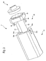
- FIG. 3 is a view in perspective and in the dissociated state of a housing 2.
- the latter essentially consists of a solid body 24 of substantially parallelepiped shape, an optical block 26 and a a cover 28.
- the optical unit 26 comprises a base 30 whose outline matches the general outer shapes of the body 24 of the housing 2 and on which stand two optical emission tubes 32 and 34 and two optical receiving tubes 36 and 38
- the optical unit is intended to be inserted into the body 24 which has, for this purpose, cavities 32a, 34a and 36a, 38a for respectively receiving the transmission tubes 32, 34 and the receiving tubes 36 and 38.
- the various elements constituting a housing 2 according to the invention may be made of any suitable material such as, in particular, injected or molded plastic.
- FIGS. 5 and 6 are cross-sectional views respectively along the lines VV and VI-VI of the housing 2, the front face 40 of which is shown in FIG. 4.
- lenses 32b, 34b and 36b, 38b are provided at the end of the emission tubes 32, 34, respectively of reception 36, 38.
- These lenses can be of mineral or organic type, be mounted one by one at the end of the tubes or come from In the latter case, the optical block 26 will preferably be but not limited to the injection of a plastic material transparent to the wavelength used and may additionally be opaque to the wavelengths not sought. It will be appreciated that each optical tube may have a more complex lens system having two or more lenses.
- the lenses 32b, 34b and 36b, 38b may be lenses of revolution, in which case their optical axes are perpendicular to their respective input and output faces. It is then necessary to mount these inclined lenses, so that their optical axes form with the general axis of symmetry z-z 'of the housing angles ⁇ , respectively ⁇ sought.
- Two light sources 40 and 42 are disposed at the bottom of the transmission tubes 32 and 34. It is preferentially, but not exclusively, two diodes emitting light in the infrared range. Similarly, two photoreceptors 44 and 46 are arranged at the bottom of the reception tubes and serve to capture the light emitted by the diodes 40 and 42 after reflection thereof on the roadway.
- the diodes 40 and 42 and the photoreceptors 44 and 46 are mounted on the surface of a printed circuit 48 by a technique well known by its name "Surface Mounted Device" or "SMD”. : Electronic components 50 are mounted on the rear face of the printed circuit 48.
- the diodes and the photoreceptors could also be mounted returned to the printed circuit 48, a technique better known by its English name “flip chip bonding”. . In the latter case, it would nevertheless be necessary to practice holes in the printed circuit opposite respectively diodes and photodetectors.
- FIGS. 7a-7c are diagrammatic views respectively of front and section along the lines AA 'and BB' of a trajectory deviation detection box according to a first embodiment of the invention.
- the housing 2 encloses (see FIG. 7b) two light sources 40 and 42 each emitting a light beam 4,6 towards the roadway, and two photodetectors 44 and 46 ( Figure 7c) for detecting the light 14, 16 after reflection on the roadway.
- Two first optical devices 32b and 34b whose optical axes are inclined by a value ⁇ relative to the general axis of symmetry zz 'of the housing 2 are each arranged in the path of one of the light beams 4,6 at its output of the corresponding light source, so as to guide said two beams of light 4,6 on the roadway in two separate zones.
- Two second optical devices 36b and 38b whose optical axes are inclined by a second value ⁇ (which may be equal to or different from the value ⁇ ) relative to the general axis of symmetry zz 'of the housing 2 are, for their part , arranged in the path of the light beams 14, 16 after they have reflected on the road and before they reach the photodetectors 44, 46.
- FIGS. 8a-8c are diagrammatic views respectively frontally and in section along lines A-A 'and B-B' of a trajectory deviation detection box according to a second embodiment of the invention.
- the housing 2 contains only one light source 40 (see FIG. 8b) which emits a primary light beam which is split into two secondary beams of light 4.6 guided on the roadway in two zones. not overlapping.
- the housing 2 always encloses two photodetectors 44 and 46 (FIG. 8c) and the second optical devices 36 and 38b associated with them.
- a spot of light on the roadway corresponds to a single photodetector.
- FIGS. 9a-9c are diagrammatic front and sectional views respectively along lines AA 'and BB' of a trajectory deviation detection box according to a third embodiment of the invention.
- the housing 2 encloses (see FIG. 9b) two light sources 40 and 42 which each emit a light beam 4,6 in the direction of the roadway, and the first two optical devices 32b and 34b associated with said sources.
- the housing 2 contains only one photodetector 44 (FIG. 9c), the two second optical devices 36b and 38b having, in this case, the function of directing the light beams 14, 16 to the single photodetector 44 after said beams 14,16 have reflected on the roadway.
- This solution is economical because it uses only one photodetector. It will of course be understood that the two light sources 40 and 42 will not have to be lit simultaneously so that the photodetector can discriminate light coming alternately from one of these two light sources.
Landscapes
- Engineering & Computer Science (AREA)
- Multimedia (AREA)
- Mechanical Engineering (AREA)
- Physics & Mathematics (AREA)
- Remote Sensing (AREA)
- Electromagnetism (AREA)
- General Physics & Mathematics (AREA)
- Radar, Positioning & Navigation (AREA)
- Computer Networks & Wireless Communication (AREA)
- Traffic Control Systems (AREA)
- Geophysics And Detection Of Objects (AREA)
- Discharge Of Articles From Conveyors (AREA)
- Road Signs Or Road Markings (AREA)
- Road Repair (AREA)
- Control Of Position, Course, Altitude, Or Attitude Of Moving Bodies (AREA)
- Optical Radar Systems And Details Thereof (AREA)
Claims (16)
- Vorrichtung zum Erfassen des Überfahrens einer horizontalen Begrenzungsmarkierung von Fahrspuren einer Fahrbahn für Kraftfahrzeuge, dadurch gekennzeichnet, dass sie wenigstens ein Gehäuse (2), das dazu vorgesehen ist, unter dem Fahrzeug angeordnet zu werden, und das Master- und Slave-Mittel enthält, die ermöglichen, zwei Lichtstrahlenbündel (4, 6) auf die Fahrbahn (8) in zwei verschiedenen Zonen (10, 12) zu projizieren, und verschiedene Mittel, die jedes der zwei Lichtstrahlenbündel (14, 16) nach ihrer Reflexion auf der Fahrbahn (8) einfangen, umfasst.
- Erfassungsvorrichtung nach Anspruch 1, dadurch gekennzeichnet, dass das wenigstens eine Gehäuse (2), das eine allgemeine Symmetrieachse (z-z') aufweist, eine einzige Lichtquelle (40), die ein primäres Lichtstrahlenbündel (50) in Richtung zur Fahrbahn (8) aussendet, und wenigstens einen Photodetektor (44, 46), der dazu bestimmt ist, das Licht nach seiner Reflexion auf der Fahrbahn (8) zu erfassen, einschließt, wobei zwei erste optische Vorrichtungen, deren optische Achsen in Bezug auf die allgemeine Symmetrieachse (z-z') des Gehäuses um einen ersten Wert (α) geneigt sind, in der Bahn des primären Lichtstrahls (50) am Ausgang der Lichtquelle angeordnet sind, so dass das primäre Lichtstrahlenbündel (50) in zwei sekundäre Lichtstrahlenbündel (4, 6), die auf der Fahrbahn (8) in zwei verschiedenen Zonen (10, 12) projiziert werden, getrennt wird, und zwei zweite optische Vorrichtungen, deren optische Achsen in Bezug auf die allgemeine Symmetrieachse (z-z') des Gehäuses (2) um einen zweiten Wert (β) geneigt sind, in der Bahn der sekundären Lichtstrahlenbündel, nachdem diese auf der Fahrbahn (8) reflektiert worden sind und bevor diese den wenigstens einen Photodetektor (44, 46) erreichen, angeordnet sind.
- Erfassungsvorrichtung nach Anspruch 1, dadurch gekennzeichnet, dass das wenigstens eine Gehäuse (2), das eine allgemeine Symmetrieachse (z-z') aufweist, zwei Lichtquellen (40, 42), die jeweils ein Lichtstrahlenbündel (4, 6) in Richtung zur Fahrbahn (8) aussenden, und wenigstens einen Photodetektor (44, 46), der dazu bestimmt ist, das Licht nach seiner Reflexion auf der Fahrbahn (8) zu erfassen, einschließt, wobei zwei erste optische Vorrichtungen, deren optische Achsen in Bezug auf die allgemeine Symmetrieachse (z-z') des Gehäuses (2) um einen ersten Wert (α) geneigt sind, in der Bahn jeweils eines der Lichtstrahlenbündel (4, 6) am Ausgang der entsprechenden Lichtquelle (40, 42) angeordnet sind, so dass die zwei Lichtstrahlenbündel (4, 6) auf die Fahrbahn (8) in zwei verschiedenen Zonen (10, 12) projiziert werden, und zwei zweite optische Vorrichtungen, deren optische Achsen in Bezug auf die allgemeine Symmetrieachse (z-z') des Gehäuses (2) um einen zweiten Wert (β) geneigt sind, in der Bahn der Lichtstrahlenbündel (14, 16), nachdem diese auf der Fahrbahn (8) reflektiert worden sind und bevor diese den wenigstens einen Photodetektor (44, 46) erreichen, angeordnet sind.
- Erfassungsvorrichtung nach einem der Ansprüche 2 oder 3, dadurch gekennzeichnet, dass die zwei ersten und die zwei zweiten optischen Vorrichtungen jeweils wenigstens eine Linse (32b, 34b, 36b, 38b) umfassen.
- Erfassungsvorrichtung nach Anspruch 4, dadurch gekennzeichnet, dass die Linsen rotationssymmetrisch sind oder keine axiale Symmetrie aufweisen.
- Erfassungsvorrichtung nach einem der Ansprüche 4 oder 5, dadurch gekennzeichnet, dass die Linsen (32b, 34b, 36b, 38b) vom mineralischen Typ sind.
- Erfassungsvorrichtung nach einem der Ansprüche 4 oder 5, dadurch gekennzeichnet, dass die Linsen (32b, 34b, 36b, 38b) vom organischen Typ sind.
- Erfassungsvorrichtung nach einem der Ansprüche 4 bis 7, dadurch gekennzeichnet, dass das Gehäuse (2) einen Körper (24) und einen die Linsen tragenden optischen Block (26) umfasst.
- Erfassungsvorrichtung nach Anspruch 8, dadurch gekennzeichnet, dass die Linsen (32b, 34b, 36b, 38b) an dem optischen Block (26) einzeln angebracht sind.
- Erfassungsvorrichtung nach Anspruch 8, dadurch gekennzeichnet, dass die Linsen (32b, 34b, 36b, 38b) mit dem optischen Block (26) einteilig hergestellt sind.
- Erfassungsvorrichtung nach einem der Ansprüche 7 bis 10, dadurch gekennzeichnet, dass der optische Block (26) einen Sockel (30) aufweist, auf dem zwei optische Senderöhren (32, 34) und zwei optische Empfangsröhren (36, 38) emporragen.
- Erfassungsvorrichtung nach Anspruch 11, dadurch gekennzeichnet, dass der Körper (24) des Gehäuses (2) Hohlräume (32a, 34a, 36a, 38a) aufweist, die dazu bestimmt sind, die Senderöhren (32, 34) und Empfangsröhren (36, 38) des optischen Blocks (26) aufzunehmen.
- Erfassungsvorrichtung nach einem der Ansprüche 2 bis 12, dadurch gekennzeichnet, dass die Lichtquellen (40, 42) Elektrolumineszenzdioden umfassen, die im Infrarotbereich aussenden.
- Erfassungsvorrichtung nach einem der Ansprüche 2 bis 13, dadurch gekennzeichnet, dass die Lichtquellen (40, 42) und die Photoempfänger (44, 46) durch SMD oder durch Flipchip-Kontakt auf einer gedruckten Schaltung (48) montiert sind.
- Erfassungsvorrichtung nach einem der Ansprüche 1 bis 14, dadurch gekennzeichnet, dass die Lichtstrahlenbündel (4, 6) auf die Oberfläche der Fahrbahn (8) fokussiert sind.
- Erfassungsvorrichtung nach einem der Ansprüche 2 bis 15, dadurch gekennzeichnet, dass die zwei ersten und die zwei zweiten optischen Vorrichtungen einen Schirm aufweisen, der schräg vor den Lichtquellen (40, 42) angeordnet ist und durch den ein Loch verläuft.
Priority Applications (1)
| Application Number | Priority Date | Filing Date | Title |
|---|---|---|---|
| EP03766134A EP1540372B1 (de) | 2002-07-25 | 2003-07-08 | Einrichtung zur erkennung des überfahrens einer strassenmarkierung für ein kraftfahrzeug |
Applications Claiming Priority (4)
| Application Number | Priority Date | Filing Date | Title |
|---|---|---|---|
| EP02078059A EP1387184A1 (de) | 2002-07-25 | 2002-07-25 | Spurabdriftdetektionsgerät |
| EP02078059 | 2002-07-25 | ||
| EP03766134A EP1540372B1 (de) | 2002-07-25 | 2003-07-08 | Einrichtung zur erkennung des überfahrens einer strassenmarkierung für ein kraftfahrzeug |
| PCT/EP2003/007326 WO2004013653A1 (fr) | 2002-07-25 | 2003-07-08 | Dispositif de detection du franchissement d'une ligne de marquage de route pour vehicule automobile |
Publications (2)
| Publication Number | Publication Date |
|---|---|
| EP1540372A1 EP1540372A1 (de) | 2005-06-15 |
| EP1540372B1 true EP1540372B1 (de) | 2006-05-03 |
Family
ID=30011216
Family Applications (2)
| Application Number | Title | Priority Date | Filing Date |
|---|---|---|---|
| EP02078059A Withdrawn EP1387184A1 (de) | 2002-07-25 | 2002-07-25 | Spurabdriftdetektionsgerät |
| EP03766134A Expired - Lifetime EP1540372B1 (de) | 2002-07-25 | 2003-07-08 | Einrichtung zur erkennung des überfahrens einer strassenmarkierung für ein kraftfahrzeug |
Family Applications Before (1)
| Application Number | Title | Priority Date | Filing Date |
|---|---|---|---|
| EP02078059A Withdrawn EP1387184A1 (de) | 2002-07-25 | 2002-07-25 | Spurabdriftdetektionsgerät |
Country Status (7)
| Country | Link |
|---|---|
| US (1) | US7199368B2 (de) |
| EP (2) | EP1387184A1 (de) |
| AT (1) | ATE325353T1 (de) |
| AU (1) | AU2003249988A1 (de) |
| DE (1) | DE60305048T2 (de) |
| ES (1) | ES2263029T3 (de) |
| WO (1) | WO2004013653A1 (de) |
Families Citing this family (7)
| Publication number | Priority date | Publication date | Assignee | Title |
|---|---|---|---|---|
| TWI236990B (en) * | 2004-10-07 | 2005-08-01 | Chi-Ruei Huang | Pre-warning system of deviated lane for vehicles |
| DE102005023862A1 (de) * | 2005-05-24 | 2006-11-30 | Valeo Schalter Und Sensoren Gmbh | Spurerkennungssystem und Betriebsverfahren hierfür |
| FR2888945B1 (fr) * | 2005-07-22 | 2013-10-25 | Johnson Controls Tech Co | Dispositif de detection au moyen de faisceaux croises du franchissement d'une ligne delimitant une voie de circulation sur une surface |
| US20090284361A1 (en) * | 2008-05-19 | 2009-11-19 | John Boddie | Driver scoring system with lane changing detection and warning system |
| DE102014217694A1 (de) * | 2014-09-04 | 2016-03-10 | Volkswagen Aktiengesellschaft | Spurhalteassistent |
| RU2605650C1 (ru) * | 2015-07-07 | 2016-12-27 | Федеральное государственное бюджетное образовательное учреждение высшего профессионального образования "Московский автомобильно-дорожный государственный технический университет (МАДИ)" | Способ безопасного движения транспортного средства по автомобильной дороге с осевой разделительной линией |
| US20200149955A1 (en) * | 2018-11-09 | 2020-05-14 | Vincent Puruczky | Raised pavement marker detector |
Family Cites Families (14)
| Publication number | Priority date | Publication date | Assignee | Title |
|---|---|---|---|---|
| US3201750A (en) * | 1962-01-02 | 1965-08-17 | Morin Lawrence | Automobile swerve alarm system |
| US3739179A (en) * | 1971-01-07 | 1973-06-12 | I Krekow | Radiation sensitive traffic warning system |
| JPS5512605B2 (de) * | 1971-11-30 | 1980-04-03 | ||
| US4348652A (en) * | 1980-09-29 | 1982-09-07 | Robert R. Barnes | Driver alert system |
| DE3071811D1 (en) * | 1980-10-09 | 1986-12-04 | Claude Fricot | Apparatus for indicating trajectory change |
| FR2637715B2 (fr) * | 1988-07-28 | 1994-08-26 | Sectronic Sa | Detecteur de derive de trajectoire |
| SE461260B (sv) * | 1988-10-24 | 1990-01-29 | Goeran Persson | Foer motorfordon avsedd varningsanordning foer avgivande av varningssignaler |
| US5463384A (en) * | 1991-02-11 | 1995-10-31 | Auto-Sense, Ltd. | Collision avoidance system for vehicles |
| DE19507957C1 (de) * | 1995-03-07 | 1996-09-12 | Daimler Benz Ag | Fahrzeug mit optischer Abtasteinrichtung für einen seitlichen Fahrbahnbereich |
| US5568137A (en) * | 1995-09-26 | 1996-10-22 | Liu; Jian S. | Vehicle lane guide and alerting device |
| JP2000147124A (ja) * | 1998-11-12 | 2000-05-26 | Denso Corp | 車載レーダ装置 |
| FR2821963B1 (fr) * | 2001-03-08 | 2003-04-25 | Peugeot Citroen Automobiles Sa | Dispositif de detection d'une surface de roulement et vehicule utilisant un tel dispositif |
| US6498570B2 (en) * | 2001-05-24 | 2002-12-24 | Phillip N. Ross | Optical highway line detector |
| US6741186B2 (en) * | 2001-05-24 | 2004-05-25 | Phillip N. Ross | Infrared road line detector |
-
2002
- 2002-07-25 EP EP02078059A patent/EP1387184A1/de not_active Withdrawn
-
2003
- 2003-07-08 DE DE60305048T patent/DE60305048T2/de not_active Expired - Lifetime
- 2003-07-08 AT AT03766134T patent/ATE325353T1/de not_active IP Right Cessation
- 2003-07-08 AU AU2003249988A patent/AU2003249988A1/en not_active Abandoned
- 2003-07-08 ES ES03766134T patent/ES2263029T3/es not_active Expired - Lifetime
- 2003-07-08 EP EP03766134A patent/EP1540372B1/de not_active Expired - Lifetime
- 2003-07-08 WO PCT/EP2003/007326 patent/WO2004013653A1/fr not_active Ceased
- 2003-07-08 US US10/522,317 patent/US7199368B2/en not_active Expired - Lifetime
Also Published As
| Publication number | Publication date |
|---|---|
| EP1387184A1 (de) | 2004-02-04 |
| DE60305048D1 (de) | 2006-06-08 |
| EP1540372A1 (de) | 2005-06-15 |
| WO2004013653A1 (fr) | 2004-02-12 |
| US20050231389A1 (en) | 2005-10-20 |
| ATE325353T1 (de) | 2006-06-15 |
| AU2003249988A1 (en) | 2004-02-23 |
| US7199368B2 (en) | 2007-04-03 |
| ES2263029T3 (es) | 2006-12-01 |
| DE60305048T2 (de) | 2006-12-07 |
Similar Documents
| Publication | Publication Date | Title |
|---|---|---|
| EP1553429B1 (de) | System und Verfahren für ein Fahrzeug um die Verkehrsbedingungen zu detektieren | |
| EP0904552B1 (de) | Verfahren und vorrichtung zum messen von parklücken für fahrzeuge | |
| FR2759043A1 (fr) | Installation pour regler la portee des projecteurs d'un vehicule | |
| EP3803198B1 (de) | Lichtmodul für ein automobil-fahrzeug | |
| FR2834110A1 (fr) | Dispositif d'aide a la conduite pour vehicule automobile optimise par synergie avec un eclairage adaptatif | |
| WO2017174674A1 (fr) | Procédé de commande d'affichage automatique d'un pictogramme représentatif de la présence d'une perturbation en avant du véhicule | |
| EP1027636B1 (de) | Verfahren und vorrichtung zur ortung und führung eines mit einer linearen kamera versehenen fahrzeugs | |
| EP1540372B1 (de) | Einrichtung zur erkennung des überfahrens einer strassenmarkierung für ein kraftfahrzeug | |
| EP2754950B1 (de) | Beleuchtungstaschenlampe für Kraftfahrzeug | |
| EP1515293A1 (de) | Vorrichtung zur Hindernisserkennung mit einem stereoskopischen Abbildungssystem mit zwei optischen Sensoren | |
| FR3078381A1 (fr) | Dispositif lumineux pour vehicule automobile, et unite d'eclairage et/ou de signalisation muni d'un tel dispositif | |
| EP4058327A1 (de) | Beleuchtungsmodul für einen seitenabschnitt eines fahrzeuges | |
| EP3432031A1 (de) | Erkennung von objekten für kraftfahrzeug | |
| EP4058721B1 (de) | Beleuchtungsmodul für ein seitenteil eines fahrzeugs | |
| FR3038118A1 (fr) | Dispositif et procede de detection d'objets | |
| EP0606177B1 (de) | Rechnergestütztes Steuerungssystem für Kraftfahrzeuge mit Vorhersage von möglichen Kollisionen | |
| EP3342640B1 (de) | Warnleuchtsystem für kraftfahrzeug, und warnleuchtverfahren | |
| FR3104673A1 (fr) | Module d’éclairage pour l’éclairage d'une zone latérale d’un véhicule | |
| EP4136475A1 (de) | Verfahren zur erkennung einer verkehrsstausituation in einem kraftfahrzeug | |
| FR2870355A1 (fr) | Systeme d'assistance a la conduite d'un vehicule automobile par detection de l'environnement | |
| FR3080923A1 (fr) | Dispositif et procede de detection d'objets | |
| EP4713713A1 (de) | Fahrzeug mit extremem sensor | |
| FR3049525A1 (fr) | Procede de commande d'affichage automatique d'un pictogramme representatif de la presence d'asperites sur la chaussee | |
| FR3082485A1 (fr) | Dispositif d'affichage pour l'aide a la conduite d'un conducteur d'un vehicule | |
| FR2887342A1 (fr) | Procede et dispositif de telemetrie notamment pour vehicule automobile |
Legal Events
| Date | Code | Title | Description |
|---|---|---|---|
| PUAI | Public reference made under article 153(3) epc to a published international application that has entered the european phase |
Free format text: ORIGINAL CODE: 0009012 |
|
| 17P | Request for examination filed |
Effective date: 20050225 |
|
| AK | Designated contracting states |
Kind code of ref document: A1 Designated state(s): AT BE BG CH CY CZ DE DK EE ES FI FR GB GR HU IE IT LI LU MC NL PT RO SE SI SK TR |
|
| AX | Request for extension of the european patent |
Extension state: AL LT LV MK |
|
| GRAP | Despatch of communication of intention to grant a patent |
Free format text: ORIGINAL CODE: EPIDOSNIGR1 |
|
| DAX | Request for extension of the european patent (deleted) | ||
| GRAS | Grant fee paid |
Free format text: ORIGINAL CODE: EPIDOSNIGR3 |
|
| GRAA | (expected) grant |
Free format text: ORIGINAL CODE: 0009210 |
|
| AK | Designated contracting states |
Kind code of ref document: B1 Designated state(s): AT BE BG CH CY CZ DE DK EE ES FI FR GB GR HU IE IT LI LU MC NL PT RO SE SI SK TR |
|
| PG25 | Lapsed in a contracting state [announced via postgrant information from national office to epo] |
Ref country code: FI Free format text: LAPSE BECAUSE OF FAILURE TO SUBMIT A TRANSLATION OF THE DESCRIPTION OR TO PAY THE FEE WITHIN THE PRESCRIBED TIME-LIMIT Effective date: 20060503 Ref country code: RO Free format text: LAPSE BECAUSE OF FAILURE TO SUBMIT A TRANSLATION OF THE DESCRIPTION OR TO PAY THE FEE WITHIN THE PRESCRIBED TIME-LIMIT Effective date: 20060503 Ref country code: IE Free format text: LAPSE BECAUSE OF FAILURE TO SUBMIT A TRANSLATION OF THE DESCRIPTION OR TO PAY THE FEE WITHIN THE PRESCRIBED TIME-LIMIT Effective date: 20060503 Ref country code: SI Free format text: LAPSE BECAUSE OF FAILURE TO SUBMIT A TRANSLATION OF THE DESCRIPTION OR TO PAY THE FEE WITHIN THE PRESCRIBED TIME-LIMIT Effective date: 20060503 Ref country code: AT Free format text: LAPSE BECAUSE OF FAILURE TO SUBMIT A TRANSLATION OF THE DESCRIPTION OR TO PAY THE FEE WITHIN THE PRESCRIBED TIME-LIMIT Effective date: 20060503 Ref country code: SK Free format text: LAPSE BECAUSE OF FAILURE TO SUBMIT A TRANSLATION OF THE DESCRIPTION OR TO PAY THE FEE WITHIN THE PRESCRIBED TIME-LIMIT Effective date: 20060503 Ref country code: CZ Free format text: LAPSE BECAUSE OF FAILURE TO SUBMIT A TRANSLATION OF THE DESCRIPTION OR TO PAY THE FEE WITHIN THE PRESCRIBED TIME-LIMIT Effective date: 20060503 Ref country code: NL Free format text: LAPSE BECAUSE OF FAILURE TO SUBMIT A TRANSLATION OF THE DESCRIPTION OR TO PAY THE FEE WITHIN THE PRESCRIBED TIME-LIMIT Effective date: 20060503 |
|
| REG | Reference to a national code |
Ref country code: GB Ref legal event code: FG4D Free format text: NOT ENGLISH |
|
| REG | Reference to a national code |
Ref country code: CH Ref legal event code: EP |
|
| REF | Corresponds to: |
Ref document number: 60305048 Country of ref document: DE Date of ref document: 20060608 Kind code of ref document: P |
|
| REG | Reference to a national code |
Ref country code: DE Ref legal event code: R096 Ref document number: 60305048 Country of ref document: DE Effective date: 20060608 |
|
| REG | Reference to a national code |
Ref country code: IE Ref legal event code: FG4D Free format text: LANGUAGE OF EP DOCUMENT: FRENCH |
|
| PG25 | Lapsed in a contracting state [announced via postgrant information from national office to epo] |
Ref country code: BE Free format text: LAPSE BECAUSE OF NON-PAYMENT OF DUE FEES Effective date: 20060731 Ref country code: MC Free format text: LAPSE BECAUSE OF NON-PAYMENT OF DUE FEES Effective date: 20060731 |
|
| PG25 | Lapsed in a contracting state [announced via postgrant information from national office to epo] |
Ref country code: SE Free format text: LAPSE BECAUSE OF FAILURE TO SUBMIT A TRANSLATION OF THE DESCRIPTION OR TO PAY THE FEE WITHIN THE PRESCRIBED TIME-LIMIT Effective date: 20060803 Ref country code: DK Free format text: LAPSE BECAUSE OF FAILURE TO SUBMIT A TRANSLATION OF THE DESCRIPTION OR TO PAY THE FEE WITHIN THE PRESCRIBED TIME-LIMIT Effective date: 20060803 |
|
| REG | Reference to a national code |
Ref country code: CH Ref legal event code: NV Representative=s name: ICB INGENIEURS CONSEILS EN BREVETS SA |
|
| PG25 | Lapsed in a contracting state [announced via postgrant information from national office to epo] |
Ref country code: PT Free format text: LAPSE BECAUSE OF FAILURE TO SUBMIT A TRANSLATION OF THE DESCRIPTION OR TO PAY THE FEE WITHIN THE PRESCRIBED TIME-LIMIT Effective date: 20061003 |
|
| GBT | Gb: translation of ep patent filed (gb section 77(6)(a)/1977) |
Effective date: 20060911 |
|
| NLV1 | Nl: lapsed or annulled due to failure to fulfill the requirements of art. 29p and 29m of the patents act | ||
| REG | Reference to a national code |
Ref country code: ES Ref legal event code: FG2A Ref document number: 2263029 Country of ref document: ES Kind code of ref document: T3 |
|
| REG | Reference to a national code |
Ref country code: IE Ref legal event code: FD4D |
|
| PLBE | No opposition filed within time limit |
Free format text: ORIGINAL CODE: 0009261 |
|
| STAA | Information on the status of an ep patent application or granted ep patent |
Free format text: STATUS: NO OPPOSITION FILED WITHIN TIME LIMIT |
|
| 26N | No opposition filed |
Effective date: 20070206 |
|
| REG | Reference to a national code |
Ref country code: DE Ref legal event code: R097 Ref document number: 60305048 Country of ref document: DE Effective date: 20070206 |
|
| BERE | Be: lapsed |
Owner name: EM MICROELECTRONIC-MARIN SA Effective date: 20060731 |
|
| PG25 | Lapsed in a contracting state [announced via postgrant information from national office to epo] |
Ref country code: GR Free format text: LAPSE BECAUSE OF FAILURE TO SUBMIT A TRANSLATION OF THE DESCRIPTION OR TO PAY THE FEE WITHIN THE PRESCRIBED TIME-LIMIT Effective date: 20060804 |
|
| PG25 | Lapsed in a contracting state [announced via postgrant information from national office to epo] |
Ref country code: BG Free format text: LAPSE BECAUSE OF FAILURE TO SUBMIT A TRANSLATION OF THE DESCRIPTION OR TO PAY THE FEE WITHIN THE PRESCRIBED TIME-LIMIT Effective date: 20060803 Ref country code: EE Free format text: LAPSE BECAUSE OF FAILURE TO SUBMIT A TRANSLATION OF THE DESCRIPTION OR TO PAY THE FEE WITHIN THE PRESCRIBED TIME-LIMIT Effective date: 20060503 |
|
| PG25 | Lapsed in a contracting state [announced via postgrant information from national office to epo] |
Ref country code: LU Free format text: LAPSE BECAUSE OF NON-PAYMENT OF DUE FEES Effective date: 20060708 Ref country code: HU Free format text: LAPSE BECAUSE OF FAILURE TO SUBMIT A TRANSLATION OF THE DESCRIPTION OR TO PAY THE FEE WITHIN THE PRESCRIBED TIME-LIMIT Effective date: 20061104 Ref country code: TR Free format text: LAPSE BECAUSE OF FAILURE TO SUBMIT A TRANSLATION OF THE DESCRIPTION OR TO PAY THE FEE WITHIN THE PRESCRIBED TIME-LIMIT Effective date: 20060503 |
|
| PG25 | Lapsed in a contracting state [announced via postgrant information from national office to epo] |
Ref country code: CY Free format text: LAPSE BECAUSE OF FAILURE TO SUBMIT A TRANSLATION OF THE DESCRIPTION OR TO PAY THE FEE WITHIN THE PRESCRIBED TIME-LIMIT Effective date: 20060503 |
|
| PGFP | Annual fee paid to national office [announced via postgrant information from national office to epo] |
Ref country code: GB Payment date: 20130626 Year of fee payment: 11 |
|
| PGFP | Annual fee paid to national office [announced via postgrant information from national office to epo] |
Ref country code: ES Payment date: 20130716 Year of fee payment: 11 |
|
| GBPC | Gb: european patent ceased through non-payment of renewal fee |
Effective date: 20140708 |
|
| PG25 | Lapsed in a contracting state [announced via postgrant information from national office to epo] |
Ref country code: GB Free format text: LAPSE BECAUSE OF NON-PAYMENT OF DUE FEES Effective date: 20140708 |
|
| REG | Reference to a national code |
Ref country code: FR Ref legal event code: PLFP Year of fee payment: 14 |
|
| PG25 | Lapsed in a contracting state [announced via postgrant information from national office to epo] |
Ref country code: ES Free format text: LAPSE BECAUSE OF NON-PAYMENT OF DUE FEES Effective date: 20140709 |
|
| REG | Reference to a national code |
Ref country code: FR Ref legal event code: PLFP Year of fee payment: 15 |
|
| REG | Reference to a national code |
Ref country code: FR Ref legal event code: PLFP Year of fee payment: 16 |
|
| PGFP | Annual fee paid to national office [announced via postgrant information from national office to epo] |
Ref country code: IT Payment date: 20220621 Year of fee payment: 20 |
|
| PGFP | Annual fee paid to national office [announced via postgrant information from national office to epo] |
Ref country code: FR Payment date: 20220622 Year of fee payment: 20 |
|
| PGFP | Annual fee paid to national office [announced via postgrant information from national office to epo] |
Ref country code: DE Payment date: 20220621 Year of fee payment: 20 |
|
| PGFP | Annual fee paid to national office [announced via postgrant information from national office to epo] |
Ref country code: CH Payment date: 20220802 Year of fee payment: 20 |
|
| REG | Reference to a national code |
Ref country code: DE Ref legal event code: R071 Ref document number: 60305048 Country of ref document: DE |
|
| REG | Reference to a national code |
Ref country code: CH Ref legal event code: PL |
|
| P01 | Opt-out of the competence of the unified patent court (upc) registered |
Effective date: 20230611 |