EP1539317B1 - Modular ceramic oxygen system - Google Patents
Modular ceramic oxygen system Download PDFInfo
- Publication number
- EP1539317B1 EP1539317B1 EP03791688A EP03791688A EP1539317B1 EP 1539317 B1 EP1539317 B1 EP 1539317B1 EP 03791688 A EP03791688 A EP 03791688A EP 03791688 A EP03791688 A EP 03791688A EP 1539317 B1 EP1539317 B1 EP 1539317B1
- Authority
- EP
- European Patent Office
- Prior art keywords
- oven
- oven insert
- insert
- oxygen
- chamber
- Prior art date
- Legal status (The legal status is an assumption and is not a legal conclusion. Google has not performed a legal analysis and makes no representation as to the accuracy of the status listed.)
- Expired - Lifetime
Links
- 239000001301 oxygen Substances 0.000 title description 36
- 229910052760 oxygen Inorganic materials 0.000 title description 36
- QVGXLLKOCUKJST-UHFFFAOYSA-N atomic oxygen Chemical compound [O] QVGXLLKOCUKJST-UHFFFAOYSA-N 0.000 title description 35
- 239000000919 ceramic Substances 0.000 title description 8
- 238000010438 heat treatment Methods 0.000 claims abstract description 5
- 239000012530 fluid Substances 0.000 claims description 4
- 239000011810 insulating material Substances 0.000 claims description 4
- 239000000463 material Substances 0.000 claims description 4
- 239000007789 gas Substances 0.000 description 20
- 238000009413 insulation Methods 0.000 description 12
- 238000000034 method Methods 0.000 description 9
- 238000000926 separation method Methods 0.000 description 7
- 230000008569 process Effects 0.000 description 5
- 230000002829 reductive effect Effects 0.000 description 4
- 238000013461 design Methods 0.000 description 3
- 238000002955 isolation Methods 0.000 description 3
- 230000007257 malfunction Effects 0.000 description 3
- 238000004458 analytical method Methods 0.000 description 2
- 230000000712 assembly Effects 0.000 description 2
- 238000000429 assembly Methods 0.000 description 2
- 230000007423 decrease Effects 0.000 description 2
- 238000009826 distribution Methods 0.000 description 2
- 238000005381 potential energy Methods 0.000 description 2
- 238000003860 storage Methods 0.000 description 2
- MYMOFIZGZYHOMD-UHFFFAOYSA-N Dioxygen Chemical compound O=O MYMOFIZGZYHOMD-UHFFFAOYSA-N 0.000 description 1
- 230000004913 activation Effects 0.000 description 1
- 230000002411 adverse Effects 0.000 description 1
- 238000013459 approach Methods 0.000 description 1
- 230000004888 barrier function Effects 0.000 description 1
- 230000033228 biological regulation Effects 0.000 description 1
- 229910021525 ceramic electrolyte Inorganic materials 0.000 description 1
- 230000003247 decreasing effect Effects 0.000 description 1
- 238000010586 diagram Methods 0.000 description 1
- 229910001882 dioxygen Inorganic materials 0.000 description 1
- 238000009533 lab test Methods 0.000 description 1
- 230000000670 limiting effect Effects 0.000 description 1
- 238000004519 manufacturing process Methods 0.000 description 1
- 239000000203 mixture Substances 0.000 description 1
- 238000013021 overheating Methods 0.000 description 1
- 230000004044 response Effects 0.000 description 1
- 230000002441 reversible effect Effects 0.000 description 1
- 239000000126 substance Substances 0.000 description 1
- 230000000153 supplemental effect Effects 0.000 description 1
- 238000012360 testing method Methods 0.000 description 1
- 238000002076 thermal analysis method Methods 0.000 description 1
- 230000007723 transport mechanism Effects 0.000 description 1
Images
Classifications
-
- F—MECHANICAL ENGINEERING; LIGHTING; HEATING; WEAPONS; BLASTING
- F27—FURNACES; KILNS; OVENS; RETORTS
- F27D—DETAILS OR ACCESSORIES OF FURNACES, KILNS, OVENS OR RETORTS, IN SO FAR AS THEY ARE OF KINDS OCCURRING IN MORE THAN ONE KIND OF FURNACE
- F27D1/00—Casings; Linings; Walls; Roofs
- F27D1/04—Casings; Linings; Walls; Roofs characterised by the form, e.g. shape of the bricks or blocks used
-
- C—CHEMISTRY; METALLURGY
- C01—INORGANIC CHEMISTRY
- C01B—NON-METALLIC ELEMENTS; COMPOUNDS THEREOF; METALLOIDS OR COMPOUNDS THEREOF NOT COVERED BY SUBCLASS C01C
- C01B13/00—Oxygen; Ozone; Oxides or hydroxides in general
- C01B13/02—Preparation of oxygen
- C01B13/0229—Purification or separation processes
- C01B13/0248—Physical processing only
- C01B13/0251—Physical processing only by making use of membranes
-
- C—CHEMISTRY; METALLURGY
- C01—INORGANIC CHEMISTRY
- C01B—NON-METALLIC ELEMENTS; COMPOUNDS THEREOF; METALLOIDS OR COMPOUNDS THEREOF NOT COVERED BY SUBCLASS C01C
- C01B2210/00—Purification or separation of specific gases
- C01B2210/0043—Impurity removed
- C01B2210/0046—Nitrogen
Definitions
- the invention relates to the field of gas separation devices. More specifically, devices that use an electrochemical process to separate one gas (oxygen for example) from a mixture of gasses (air for example).
- a solid-state process is used to separate oxygen from atmospheric air for medical use.
- a ceramic oxygen generating system or COGS Such a device is called a ceramic oxygen generating system or COGS.
- the ceramic electrolyte used in the oxygen separation process must be maintained at a temperature of approximately 600°C or higher for the ionic transport mechanism to operate efficiently.
- a fairly uniform temperature distribution with the separation furnace is essential to proper and efficient system operation.
- temperature uniformity in furnace may be adversely affected. This is due, in part, to the very different surface characteristics and geometric shape factors between the separation modules and the auxiliary heaters. Reduced performance and possibly reduced system life may result from this lack of temperature uniformity.
- an oven insert for a gas generating system of the type that includes heating elements, heat exchanger, a gas generating module, an air inlet, and a product gas outlet is provided, wherein said oven insert having a plurality of interior chambers each adapted for holding at least one gas generating module, wherein the oven insert is made from suitable thermally insulating material, wherein the oven insert includes embedded heater elements providing uniform heat distributed about the interior chambers.
- the interior chambers each have an opening formed an exterior face of the oven insert.
- the openings are uniformly separated along a central axis of the face of the oven insert .
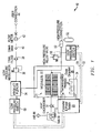
- FIG. 1 illustrates a schematic of a complete oxygen generating system 10 utilizing an electrochemical-oxygen generator in the form of a modular ceramic oxygen generator.
- This schematic depicts a power supply and controller 20 that supplies electrical power to an oven heater 24 to raise the temperature within the operating range of an oxygen-generating module assembly 22.
- the oxygen-generating module 22 assembly can include one or more oxygen-generating modules such as those disclosed in U.S. Patent No. 5,871,624 and U.S. Patent No. 5,985,113 .
- the temperature range in an oven chamber 26 may be about 500 to 800 degrees Celsius, depending on the materials used to construct the oxygen-generating module assembly 22.
- the oxygen-generating modules 22 are positioned in the oven chamber 26. After the oven chamber 26 reaches the minimum preferred operating temperature, as detected by at least one thermocouple 28 mounted in the oven chamber 26, the controller 20 begins to apply electrical power to a fan motor 30 to deliver oxygen-laden air through a counter-flow heat exchanger 32 into the oven 26 chamber to a module assembly 21 including at least one module 22.
- the controller 20 also delivers electrical power to the modules 22, and oxygen is electrochemically generated, as taught in U.S. Patent No. 5,871,624 and U.S. Patent No. 5,985,113 . Depending upon the amount of oxygen to be generated, the amount of electrical power can be varied.
- the controller 20 reduces power to the oven heater 24, to maintain the desired nominal operating temperature in the oven chamber 26.
- the oxygen being generated is delivered to a product plenum 34, which acts as a temporary oxygen storage vessel.
- the oxygen is delivered from the product plenum 34 to a low-pressure regulator 36, final filter 38, check valve 40, flow meter 42, and lastly a user-adjustable valve 44 for immediate use, for example, by a patient.
- Oxygen may also be delivered to a high-pressure connection that allows connection 50 of a removable portable oxygen storage cylinder 52.
- the portable cylinder 52 is filled automatically and can be used later.
- the controller 20 applies appropriate electrical power to the modules 22 to generate oxygen at elevated pressures until a high-pressure switch 54 detects a pressure over about 1800 psig (12,411 MPa). Upon exceeding 1800 psig (12,411 MPa), the controller 20 reduces power to the odules 22 until pressure at the high-pressure switch 54 falls below 1800 psig (12,411 MPa).
- the controller 20 also electrically monitors the low-pressure switch 58.
- This switch 54 enables regulation of the pressure delivered to the product plenum 34 and high-pressure connector 50 to a nominal pressure of about 1800 psig (12,411 MPa).
- a high-pressure relief valve 56 vents excess pressure above about 2000 psig (13,789 MPa), in the event of a malfunction of the controller 20 to limit the nominal pressure to less than 2000 psig (13,789 MPa), and to relieve excessive temperature-related pressure increases. It should be understood that the maximum normal operating pressure is approximately 1800 psig (12,411 MPa).
- the controller 20 also electrically monitors the high-pressure switch 54. If the operating pressure is below the minimum operating pressure after a given period of time, then the controller 20 activates a warning light and audible alarm (not shown).
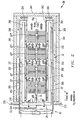
- FIG 2 illustrates a cross-section of the ceramic oxygen generating system depicting the oven 26, insulation 200, oxygen-generating module assemblies 22, heaters 24, planar counter-flow heat exchangers 32, air-flow dampers 202, and fan 30.
- the counter-flow heat exchanger is a very effective, simple, low-cost design approach.
- the oxygen-generating modules 22', 22", 22"', 22"" are manifolded together by tubes 23', 23", 23"'.
- An outlet tube 25 passes through the wall 210 to provide high-pressure oxygen to the product plenum 34 and the high-pressure connection 50.
- Cool fresh air is heated before the air enters the inner oven, and the hot air is cooled before it exits the oven 26; thereby, conserving energy.
- the fan 30 introduces cool, oxygen-laden air into the channels 280, 282 between the outer surface of the inner walls 220, 222 made of oven insulation 200 and the inner surfaces 250, 252 of the heat exchanger wall. This cool air is heated as it passes inward along the heat exchanger wall, because hot oxygen-depleted air is exiting outward from the inner oven 26 on the other side of the heat exchanger wall.
- the incoming air is also partially heated by an outer surface of the walls 220, 222 of oven insulation 200, followed by an inner surface of the walls 220, 222 of the oven insulation 200, after a 180° turn mid-way into the inner oven.
- Channels 280, 282 each flow from the fan 30 from left to right and then reverse and flow from right to left.
- the electrochemical oxygen generating modules 22 generate heat as well as oxygen. Too much oven insulation 200 and very efficient heat exchangers could result in runaway oven temperatures.
- One method of temperature control is to ensure that some amount of heater activation is always used to maintain the normal operating temperature, after the initial startup period of time.
- Another method is to adjust the fan 30 speed to cause additional air to be circulated through the oven 26 carrying away the excess heat.
- the controller 20 monitors the temperature in the inner oven 26 using one or more strategically placed thermocouples 28 (not shown in Figure 2 ) to ensure that the oven temperatures are normal. The controller 20 uses this information to adjust either the heater 24 voltage or fan 30 speed to control the temperature of the inner oven 26.
- air dampers 202 are used in the embodiment depicted in Figure 2 .
- Three dampers are each mounted to walls 260, 262 with the dampers 202 being positioned between modules 22 and opposite each other.
- the air dampers 202 shown allow some oxygen-laden air to enter the module chamber or inner oven 26 before completing the entire heat exchanger flow-path to the inner oven. If all oxygen-laden air were forced to traverse the entire heat exchanger flow-path, a higher temperature gradient would occur across the series of modules 22 in the oven. The air would be progressively heated as it passes over each module 22.
- dampers 202 are adjustable and can be manually adjusted during the assembly of the system 10 and during an initial start up test process after completion of the manufacturing and assembly process of the system 10.
- dampers 202 include damper flaps 204 which are mounted to a suitable cylindrical rod (not shown) that extends through the inner oven insulation and support structure to outside the inner oven 26. The external ends of the damper rods can be rotated and secured in the preferred orientation during the assembly process. Alternately, the dampers could be adjusted automatically by the controller 20, based upon the inner oven 26 temperatures measured by the thermocouples 28.
- electromechanical damper actuators are available that could be used.
- the basic concept of the present invention is to improve overall system efficiency by employing several smaller separation oven inserts instead of one large one.
- These smaller modular oven inserts are thermally optimized (in terms of heat loss and temperature uniformity) to operate in a relatively narrow range product flow rates.
- additional modules 22 are turned on to meet the increased demand for the product gas.
- individual module assemblies 22 are either turned off or switched to a lower-temperature "standby" mode to conserve power.
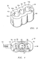
- a modular oven insert 110 is shown in Figure 3 . This oven insert 110 has three separate heated chambers 112a, 112b, 112c that may be operated independently of each other.
- a module assembly including at lest one module 22 is fitted within each chamber 112.
- each of the oven chambers 112 should have at least one heater 114 and a controller 116 affecting the electrically connected and responsive heater 114. It is preferred that the heaters 114 are formed within or embedded within the interior of the chamber walls 118 such that each chamber 112 is effectively, uniformly heated by the corresponding heater 114.
- the oven insert 110 for a gas generating system of the type that includes heating elements, heat exchanger, a gas generating module 22, an air inlet, and a product gas outlet, is formed with a plurality of interior chambers 112.
- the interior chambers 112 are adapted for holding at least one gas generating module 22 and are separated one from another by an intermediary interstitial wall 130.
- the interior chambers 112 each have an opening 122 formed in exterior face 124 of the oven insert 110.
- the openings 122 are preferably uniformly separated along a central axis 126 of the exterior face 124 of the oven insert 110.
- the gas generating components such as the gas generating module 22, can be positioned within the oven insert 110 by being mounted in the selected chamber 112 through a respective opening 122.
- FIG 4 shows results of a 2D finite element thermal analysis of the oven insert configuration previously shown in Figure 3 .
- the center module 112b is operating.
- Equal temperature gradient distribution lines 128 are shown.
- the relatively thin interstitial center walls 130 between the center 112b and outside furnace modules 112a, 112c does not typically provide adequate thermal isolation. Consequently, a significant amount of heat may be lost into the non- operating modules. This problem is simply remedied by adding more insulation between the furnace modules 112 or between oven chamber modules or oven inserts 110.
- the walls 118 of the oven insert 110 are made from suitable thermally insulating material that is selected to maintain stability at the operating temperatures of the gas generator.
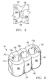
- a type of insulation for the interstitial walls may be a chamber or a passageway 132 may be formed or embedded within the interstitial wall 130 for containing or passing a fluid or a gas or creating a gas envelope to reduce thermal conductivity from and further isolate one interior chamber 112 and an adjacent chamber 112.
- a series of bore holes 132 ( Figure 4 ) formed in the interstitial wall 130 may pass a selected thermal conductive or thermal nonconductive fluid or gas to further heat, cool or regulate the temperature of the interior wall 130 and the surrounding environment.
- interstitial wall 130 is formed from a different material having a desired thermal conductivity characteristic.
- lines 134 in Figure 5 depicts a boundary with wall portion 136 being formed from the different thermally insulating material than the remainder of the chamber walls 118.
- the oven insert 110 could be formed from at least two separate enclosure bodies 140.
- Each separate enclosure body 140 has at least one interior chamber 112, although there could be enclosure bodies with either no interior chambers or with more than one interior chamber.
- the separate enclosure bodies 140 preferably have an outer surface 142 formed to be compatible with an outer surface or face 142 of an adjacent separate enclosure body 140.
- Such insulating methods and other insulating techniques would further isolate one chamber 122 from another and tend to create a thermal barrier comprising the separator walls 130.
- a COGS “module” consists of several ceramic oxygen generating elements or Integrated Manifold and Tube modules (IMATs) inside an oven insert or enclosure (including insulation, heating elements, heat exchanger, an air inlet, and a product gas outlet). Each module produces a specific amount oxygen at a given level of power consumption.
- Oxygen generating systems are composed of a number of modules that depends on the peak oxygen flow requirement, system size requirement, and power consumption requirement.
Landscapes
- Chemical & Material Sciences (AREA)
- Engineering & Computer Science (AREA)
- Organic Chemistry (AREA)
- Mechanical Engineering (AREA)
- General Engineering & Computer Science (AREA)
- Analytical Chemistry (AREA)
- Inorganic Chemistry (AREA)
- Furnace Details (AREA)
- Oxygen, Ozone, And Oxides In General (AREA)
- Percussion Or Vibration Massage (AREA)
- Valve Housings (AREA)
- Feeding, Discharge, Calcimining, Fusing, And Gas-Generation Devices (AREA)
Applications Claiming Priority (5)
| Application Number | Priority Date | Filing Date | Title |
|---|---|---|---|
| US604117 | 2000-06-26 | ||
| US31950702P | 2002-08-28 | 2002-08-28 | |
| US319507P | 2002-08-28 | ||
| US10/604,117 US6783646B2 (en) | 2002-08-28 | 2003-06-26 | Modular ceramic oxygen system |
| PCT/US2003/025823 WO2004020063A2 (en) | 2002-08-28 | 2003-08-15 | Modular ceramic oxygen system |
Publications (3)
| Publication Number | Publication Date |
|---|---|
| EP1539317A2 EP1539317A2 (en) | 2005-06-15 |
| EP1539317A4 EP1539317A4 (en) | 2008-02-20 |
| EP1539317B1 true EP1539317B1 (en) | 2011-04-27 |
Family
ID=31981086
Family Applications (1)
| Application Number | Title | Priority Date | Filing Date |
|---|---|---|---|
| EP03791688A Expired - Lifetime EP1539317B1 (en) | 2002-08-28 | 2003-08-15 | Modular ceramic oxygen system |
Country Status (7)
| Country | Link |
|---|---|
| US (1) | US6783646B2 (enExample) |
| EP (1) | EP1539317B1 (enExample) |
| JP (1) | JP4585313B2 (enExample) |
| AT (1) | ATE507324T1 (enExample) |
| AU (1) | AU2003263894A1 (enExample) |
| DE (1) | DE60336913D1 (enExample) |
| WO (1) | WO2004020063A2 (enExample) |
Families Citing this family (26)
| Publication number | Priority date | Publication date | Assignee | Title |
|---|---|---|---|---|
| US7694674B2 (en) * | 2004-09-21 | 2010-04-13 | Carleton Life Support Systems, Inc. | Oxygen generator with storage and conservation modes |
| US7396442B2 (en) | 2005-02-08 | 2008-07-08 | Carleton Life Support Systems, Inc. | Electrochemical oxygen generator module assembly |
| EP1801070B1 (fr) * | 2005-11-24 | 2008-11-12 | L'AIR LIQUIDE, Société Anonyme pour l'Etude et l'Exploitation des Procédés Georges Claude | Procédé de production d'oxygène, à partir d'air, en particulier au moyen d'une cellule électrochimique avec membrane céramique, avec des moyens de contrôle permettant une production continue |
| US7309847B2 (en) * | 2006-01-12 | 2007-12-18 | Carleton Life Support Systems, Inc. | Ceramic oxygen generating oven |
| US8323378B2 (en) * | 2010-04-28 | 2012-12-04 | Praxair Technology, Inc. | Oxygen supply method and apparatus |
| US9561476B2 (en) | 2010-12-15 | 2017-02-07 | Praxair Technology, Inc. | Catalyst containing oxygen transport membrane |
| US9486735B2 (en) | 2011-12-15 | 2016-11-08 | Praxair Technology, Inc. | Composite oxygen transport membrane |
| CN103987681B (zh) | 2011-12-15 | 2016-08-24 | 普莱克斯技术有限公司 | 复合氧气传送膜 |
| US9969645B2 (en) | 2012-12-19 | 2018-05-15 | Praxair Technology, Inc. | Method for sealing an oxygen transport membrane assembly |
| US9453644B2 (en) | 2012-12-28 | 2016-09-27 | Praxair Technology, Inc. | Oxygen transport membrane based advanced power cycle with low pressure synthesis gas slip stream |
| US9212113B2 (en) | 2013-04-26 | 2015-12-15 | Praxair Technology, Inc. | Method and system for producing a synthesis gas using an oxygen transport membrane based reforming system with secondary reforming and auxiliary heat source |
| US9938145B2 (en) | 2013-04-26 | 2018-04-10 | Praxair Technology, Inc. | Method and system for adjusting synthesis gas module in an oxygen transport membrane based reforming system |
| US9296671B2 (en) | 2013-04-26 | 2016-03-29 | Praxair Technology, Inc. | Method and system for producing methanol using an integrated oxygen transport membrane based reforming system |
| US9611144B2 (en) | 2013-04-26 | 2017-04-04 | Praxair Technology, Inc. | Method and system for producing a synthesis gas in an oxygen transport membrane based reforming system that is free of metal dusting corrosion |
| BR112016007552A2 (pt) | 2013-10-07 | 2017-08-01 | Praxair Technology Inc | painel de membrana de transporte de oxigênio, conjuntos de tubos da membrana de transporte de oxigênio e de blocos do reator de reforma, módulo de arranjo da membrana de transporte de oxigênio, trem da fornalha de gás de síntese, e, usina de gás de síntese |
| WO2015054363A2 (en) | 2013-10-08 | 2015-04-16 | Praxair Technology, Inc. | System method for temperature control in an oxygen transport membrane based reactor |
| CA2926757C (en) | 2013-12-02 | 2020-02-25 | Praxair Technology, Inc. | Method and system for producing hydrogen using an oxygen transport membrane based reforming system with secondary reforming |
| CN105980666B (zh) | 2014-02-12 | 2019-04-09 | 普莱克斯技术有限公司 | 用于生成电力的基于氧传输膜反应器的方法和系统 |
| US10822234B2 (en) | 2014-04-16 | 2020-11-03 | Praxair Technology, Inc. | Method and system for oxygen transport membrane enhanced integrated gasifier combined cycle (IGCC) |
| US9797054B2 (en) | 2014-07-09 | 2017-10-24 | Carleton Life Support Systems Inc. | Pressure driven ceramic oxygen generation system with integrated manifold and tubes |
| WO2016057164A1 (en) | 2014-10-07 | 2016-04-14 | Praxair Technology, Inc | Composite oxygen ion transport membrane |
| US10441922B2 (en) | 2015-06-29 | 2019-10-15 | Praxair Technology, Inc. | Dual function composite oxygen transport membrane |
| US10118823B2 (en) | 2015-12-15 | 2018-11-06 | Praxair Technology, Inc. | Method of thermally-stabilizing an oxygen transport membrane-based reforming system |
| US9938146B2 (en) | 2015-12-28 | 2018-04-10 | Praxair Technology, Inc. | High aspect ratio catalytic reactor and catalyst inserts therefor |
| KR102154420B1 (ko) | 2016-04-01 | 2020-09-10 | 프랙스에어 테크놀로지, 인코포레이티드 | 촉매-함유 산소 수송막 |
| EP3797085A1 (en) | 2018-05-21 | 2021-03-31 | Praxair Technology, Inc. | Otm syngas panel with gas heated reformer |
Citations (3)
| Publication number | Priority date | Publication date | Assignee | Title |
|---|---|---|---|---|
| US2839286A (en) * | 1954-06-23 | 1958-06-17 | Clarence G Poth | Checker construction for open hearth furnaces |
| US4378045A (en) * | 1978-10-19 | 1983-03-29 | Davy Inc. | Interlocking checker tile and supporting means for regenerative heating stoves |
| US5924477A (en) * | 1995-05-09 | 1999-07-20 | Doru; Tatar | Brick for heat exchangers |
Family Cites Families (19)
| Publication number | Priority date | Publication date | Assignee | Title |
|---|---|---|---|---|
| US3638930A (en) * | 1970-04-24 | 1972-02-01 | Sylvania Electric Prod | Refractory metal boat for heat treating coils |
| US4364798A (en) * | 1980-12-30 | 1982-12-21 | Bmi, Inc. | Rebuilt coke oven heating chamber and method of making the same |
| IN154973B (enExample) * | 1981-04-09 | 1984-12-22 | Otto & Co Gmbh Dr C | |
| DE3119973C2 (de) * | 1981-05-20 | 1983-11-03 | Carl Still Gmbh & Co Kg, 4350 Recklinghausen | Beheizungseinrichtung für Regenerativverkokungsofenbatterien |
| US5378345A (en) | 1986-07-25 | 1995-01-03 | Ceramatec, Inc. | Ceramic solid electrolyte-based electrochemical oxygen concentrator cell |
| US4898792A (en) * | 1988-12-07 | 1990-02-06 | Westinghouse Electric Corp. | Electrochemical generator apparatus containing modified high temperature insulation and coated surfaces for use with hydrocarbon fuels |
| US5498487A (en) * | 1994-08-11 | 1996-03-12 | Westinghouse Electric Corporation | Oxygen sensor for monitoring gas mixtures containing hydrocarbons |
| CA2182069C (en) | 1995-08-24 | 2002-04-09 | Victor P. Crome | Modular ceramic oxygen generator |
| US5985113A (en) | 1995-08-24 | 1999-11-16 | Litton Systems, Inc. | Modular ceramic electrochemical apparatus and method of manufacture therefor |
| GB9520554D0 (en) | 1995-10-07 | 1995-12-13 | Normalair Garrett Ltd | Oxygen generating device |
| US5972182A (en) | 1997-12-05 | 1999-10-26 | Ceramphysics, Inc. | Electrode composition and application method for oxygen generators |
| US6033457A (en) * | 1998-03-23 | 2000-03-07 | Oxynet, Inc. | Oxygen generator system and method of operating the same |
| GB9808133D0 (en) | 1998-04-18 | 1998-06-17 | Normalair Garrett Ltd | Ionic conduction device |
| US6290757B1 (en) | 1999-03-26 | 2001-09-18 | Ceramphysics, Inc. | Nitrogen purification device |
| FR2792210B1 (fr) * | 1999-04-13 | 2001-09-14 | Air Liquide Sante Int | Equipement medical portable d'oxygenotherapie a domicile |
| US6352624B1 (en) | 1999-06-01 | 2002-03-05 | Northrop Grumman Corporation | Electrochemical oxygen generating system |
| US6291089B1 (en) * | 1999-10-26 | 2001-09-18 | Alliedsignal Inc. | Radial planar fuel cell stack construction for solid electrolytes |
| US6382958B1 (en) | 2000-07-12 | 2002-05-07 | Praxair Technology, Inc. | Air separation method and system for producing oxygen to support combustion in a heat consuming device |
| US6379831B1 (en) * | 2000-08-02 | 2002-04-30 | Siemens Westinghouse Power Corporation | Expanded nickel screen electrical connection supports for solid oxide fuel cells |
-
2003
- 2003-06-26 US US10/604,117 patent/US6783646B2/en not_active Expired - Lifetime
- 2003-08-15 AU AU2003263894A patent/AU2003263894A1/en not_active Abandoned
- 2003-08-15 AT AT03791688T patent/ATE507324T1/de not_active IP Right Cessation
- 2003-08-15 EP EP03791688A patent/EP1539317B1/en not_active Expired - Lifetime
- 2003-08-15 WO PCT/US2003/025823 patent/WO2004020063A2/en not_active Ceased
- 2003-08-15 DE DE60336913T patent/DE60336913D1/de not_active Expired - Lifetime
- 2003-08-15 JP JP2004532907A patent/JP4585313B2/ja not_active Expired - Lifetime
Patent Citations (3)
| Publication number | Priority date | Publication date | Assignee | Title |
|---|---|---|---|---|
| US2839286A (en) * | 1954-06-23 | 1958-06-17 | Clarence G Poth | Checker construction for open hearth furnaces |
| US4378045A (en) * | 1978-10-19 | 1983-03-29 | Davy Inc. | Interlocking checker tile and supporting means for regenerative heating stoves |
| US5924477A (en) * | 1995-05-09 | 1999-07-20 | Doru; Tatar | Brick for heat exchangers |
Also Published As
| Publication number | Publication date |
|---|---|
| US20040042944A1 (en) | 2004-03-04 |
| WO2004020063A2 (en) | 2004-03-11 |
| EP1539317A4 (en) | 2008-02-20 |
| EP1539317A2 (en) | 2005-06-15 |
| US6783646B2 (en) | 2004-08-31 |
| AU2003263894A1 (en) | 2004-03-19 |
| WO2004020063A3 (en) | 2004-05-13 |
| DE60336913D1 (de) | 2011-06-09 |
| JP2005537126A (ja) | 2005-12-08 |
| AU2003263894A8 (en) | 2004-03-19 |
| ATE507324T1 (de) | 2011-05-15 |
| JP4585313B2 (ja) | 2010-11-24 |
Similar Documents
| Publication | Publication Date | Title |
|---|---|---|
| EP1539317B1 (en) | Modular ceramic oxygen system | |
| EP1851362B1 (en) | Electrochemical oxygen generator module assembly | |
| KR100721785B1 (ko) | 전기화학적 산소 발생 시스템 | |
| US20050150226A1 (en) | Thermal storage unit and methods for using the same to heat a fluid | |
| US7693402B2 (en) | Thermal storage unit and methods for using the same to heat a fluid | |
| US20100021784A1 (en) | Solid oxide fuel cell comprising a thermal exchanger | |
| JP2005537126A5 (enExample) | ||
| KR20150128716A (ko) | 일체형 히터를 갖는 soec 스택 | |
| CN1557035A (zh) | 燃料电池系统的热控制的方法和装置 | |
| KR20170056012A (ko) | 연료 전지 유닛 및 시스템의 열 관리 | |
| US20080118787A1 (en) | Fuel cell heating | |
| JP5201848B2 (ja) | 燃料電池装置 | |
| US20230024244A1 (en) | Method for operating a heat exchanger, and energy store heat exchange system | |
| JP2005240718A (ja) | Lpg加熱装置 | |
| JP2009266588A (ja) | 燃料電池モジュール | |
| US6685235B1 (en) | System and method for attaching tubing | |
| JP2006185748A (ja) | 燃料電池パワープラントおよび燃料電池パワープラント部品の支持構造 | |
| JP2005116323A (ja) | 燃料電池の冷却構造 | |
| EP4044300A1 (en) | Fuel cell system | |
| EP1118051B1 (en) | Component heater system for use in manufacturing process | |
| WO2003059546A2 (en) | Method for attaching tubing | |
| RU2151219C1 (ru) | Генератор кислорода |
Legal Events
| Date | Code | Title | Description |
|---|---|---|---|
| PUAI | Public reference made under article 153(3) epc to a published international application that has entered the european phase |
Free format text: ORIGINAL CODE: 0009012 |
|
| 17P | Request for examination filed |
Effective date: 20050323 |
|
| AK | Designated contracting states |
Kind code of ref document: A2 Designated state(s): AT BE BG CH CY CZ DE DK EE ES FI FR GB GR HU IE IT LI LU MC NL PT RO SE SI SK TR |
|
| AX | Request for extension of the european patent |
Extension state: AL LT LV MK |
|
| RIC1 | Information provided on ipc code assigned before grant |
Ipc: 7C 25B 9/00 A |
|
| DAX | Request for extension of the european patent (deleted) | ||
| A4 | Supplementary search report drawn up and despatched |
Effective date: 20080122 |
|
| 17Q | First examination report despatched |
Effective date: 20080717 |
|
| GRAP | Despatch of communication of intention to grant a patent |
Free format text: ORIGINAL CODE: EPIDOSNIGR1 |
|
| GRAS | Grant fee paid |
Free format text: ORIGINAL CODE: EPIDOSNIGR3 |
|
| GRAA | (expected) grant |
Free format text: ORIGINAL CODE: 0009210 |
|
| AK | Designated contracting states |
Kind code of ref document: B1 Designated state(s): AT BE BG CH CY CZ DE DK EE ES FI FR GB GR HU IE IT LI LU MC NL PT RO SE SI SK TR |
|
| REG | Reference to a national code |
Ref country code: GB Ref legal event code: FG4D |
|
| REG | Reference to a national code |
Ref country code: CH Ref legal event code: EP |
|
| REG | Reference to a national code |
Ref country code: IE Ref legal event code: FG4D |
|
| REF | Corresponds to: |
Ref document number: 60336913 Country of ref document: DE Date of ref document: 20110609 Kind code of ref document: P |
|
| REG | Reference to a national code |
Ref country code: DE Ref legal event code: R096 Ref document number: 60336913 Country of ref document: DE Effective date: 20110609 |
|
| REG | Reference to a national code |
Ref country code: NL Ref legal event code: VDEP Effective date: 20110427 |
|
| PG25 | Lapsed in a contracting state [announced via postgrant information from national office to epo] |
Ref country code: SE Free format text: LAPSE BECAUSE OF FAILURE TO SUBMIT A TRANSLATION OF THE DESCRIPTION OR TO PAY THE FEE WITHIN THE PRESCRIBED TIME-LIMIT Effective date: 20110427 Ref country code: PT Free format text: LAPSE BECAUSE OF FAILURE TO SUBMIT A TRANSLATION OF THE DESCRIPTION OR TO PAY THE FEE WITHIN THE PRESCRIBED TIME-LIMIT Effective date: 20110829 |
|
| PG25 | Lapsed in a contracting state [announced via postgrant information from national office to epo] |
Ref country code: BE Free format text: LAPSE BECAUSE OF FAILURE TO SUBMIT A TRANSLATION OF THE DESCRIPTION OR TO PAY THE FEE WITHIN THE PRESCRIBED TIME-LIMIT Effective date: 20110427 Ref country code: GR Free format text: LAPSE BECAUSE OF FAILURE TO SUBMIT A TRANSLATION OF THE DESCRIPTION OR TO PAY THE FEE WITHIN THE PRESCRIBED TIME-LIMIT Effective date: 20110728 Ref country code: CY Free format text: LAPSE BECAUSE OF FAILURE TO SUBMIT A TRANSLATION OF THE DESCRIPTION OR TO PAY THE FEE WITHIN THE PRESCRIBED TIME-LIMIT Effective date: 20110427 Ref country code: FI Free format text: LAPSE BECAUSE OF FAILURE TO SUBMIT A TRANSLATION OF THE DESCRIPTION OR TO PAY THE FEE WITHIN THE PRESCRIBED TIME-LIMIT Effective date: 20110427 Ref country code: ES Free format text: LAPSE BECAUSE OF FAILURE TO SUBMIT A TRANSLATION OF THE DESCRIPTION OR TO PAY THE FEE WITHIN THE PRESCRIBED TIME-LIMIT Effective date: 20110807 Ref country code: AT Free format text: LAPSE BECAUSE OF FAILURE TO SUBMIT A TRANSLATION OF THE DESCRIPTION OR TO PAY THE FEE WITHIN THE PRESCRIBED TIME-LIMIT Effective date: 20110427 Ref country code: SI Free format text: LAPSE BECAUSE OF FAILURE TO SUBMIT A TRANSLATION OF THE DESCRIPTION OR TO PAY THE FEE WITHIN THE PRESCRIBED TIME-LIMIT Effective date: 20110427 |
|
| PG25 | Lapsed in a contracting state [announced via postgrant information from national office to epo] |
Ref country code: NL Free format text: LAPSE BECAUSE OF FAILURE TO SUBMIT A TRANSLATION OF THE DESCRIPTION OR TO PAY THE FEE WITHIN THE PRESCRIBED TIME-LIMIT Effective date: 20110427 |
|
| PG25 | Lapsed in a contracting state [announced via postgrant information from national office to epo] |
Ref country code: EE Free format text: LAPSE BECAUSE OF FAILURE TO SUBMIT A TRANSLATION OF THE DESCRIPTION OR TO PAY THE FEE WITHIN THE PRESCRIBED TIME-LIMIT Effective date: 20110427 Ref country code: CZ Free format text: LAPSE BECAUSE OF FAILURE TO SUBMIT A TRANSLATION OF THE DESCRIPTION OR TO PAY THE FEE WITHIN THE PRESCRIBED TIME-LIMIT Effective date: 20110427 |
|
| PG25 | Lapsed in a contracting state [announced via postgrant information from national office to epo] |
Ref country code: RO Free format text: LAPSE BECAUSE OF FAILURE TO SUBMIT A TRANSLATION OF THE DESCRIPTION OR TO PAY THE FEE WITHIN THE PRESCRIBED TIME-LIMIT Effective date: 20110427 Ref country code: DK Free format text: LAPSE BECAUSE OF FAILURE TO SUBMIT A TRANSLATION OF THE DESCRIPTION OR TO PAY THE FEE WITHIN THE PRESCRIBED TIME-LIMIT Effective date: 20110427 Ref country code: SK Free format text: LAPSE BECAUSE OF FAILURE TO SUBMIT A TRANSLATION OF THE DESCRIPTION OR TO PAY THE FEE WITHIN THE PRESCRIBED TIME-LIMIT Effective date: 20110427 |
|
| PLBE | No opposition filed within time limit |
Free format text: ORIGINAL CODE: 0009261 |
|
| STAA | Information on the status of an ep patent application or granted ep patent |
Free format text: STATUS: NO OPPOSITION FILED WITHIN TIME LIMIT |
|
| PG25 | Lapsed in a contracting state [announced via postgrant information from national office to epo] |
Ref country code: MC Free format text: LAPSE BECAUSE OF NON-PAYMENT OF DUE FEES Effective date: 20110831 |
|
| REG | Reference to a national code |
Ref country code: CH Ref legal event code: PL |
|
| 26N | No opposition filed |
Effective date: 20120130 |
|
| PG25 | Lapsed in a contracting state [announced via postgrant information from national office to epo] |
Ref country code: CH Free format text: LAPSE BECAUSE OF NON-PAYMENT OF DUE FEES Effective date: 20110831 Ref country code: LI Free format text: LAPSE BECAUSE OF NON-PAYMENT OF DUE FEES Effective date: 20110831 |
|
| REG | Reference to a national code |
Ref country code: IE Ref legal event code: MM4A |
|
| REG | Reference to a national code |
Ref country code: DE Ref legal event code: R097 Ref document number: 60336913 Country of ref document: DE Effective date: 20120130 |
|
| PG25 | Lapsed in a contracting state [announced via postgrant information from national office to epo] |
Ref country code: IT Free format text: LAPSE BECAUSE OF FAILURE TO SUBMIT A TRANSLATION OF THE DESCRIPTION OR TO PAY THE FEE WITHIN THE PRESCRIBED TIME-LIMIT Effective date: 20110427 |
|
| PG25 | Lapsed in a contracting state [announced via postgrant information from national office to epo] |
Ref country code: IE Free format text: LAPSE BECAUSE OF NON-PAYMENT OF DUE FEES Effective date: 20110815 |
|
| PG25 | Lapsed in a contracting state [announced via postgrant information from national office to epo] |
Ref country code: LU Free format text: LAPSE BECAUSE OF NON-PAYMENT OF DUE FEES Effective date: 20110815 |
|
| PG25 | Lapsed in a contracting state [announced via postgrant information from national office to epo] |
Ref country code: BG Free format text: LAPSE BECAUSE OF FAILURE TO SUBMIT A TRANSLATION OF THE DESCRIPTION OR TO PAY THE FEE WITHIN THE PRESCRIBED TIME-LIMIT Effective date: 20110727 |
|
| PG25 | Lapsed in a contracting state [announced via postgrant information from national office to epo] |
Ref country code: TR Free format text: LAPSE BECAUSE OF FAILURE TO SUBMIT A TRANSLATION OF THE DESCRIPTION OR TO PAY THE FEE WITHIN THE PRESCRIBED TIME-LIMIT Effective date: 20110427 |
|
| PG25 | Lapsed in a contracting state [announced via postgrant information from national office to epo] |
Ref country code: HU Free format text: LAPSE BECAUSE OF FAILURE TO SUBMIT A TRANSLATION OF THE DESCRIPTION OR TO PAY THE FEE WITHIN THE PRESCRIBED TIME-LIMIT Effective date: 20110427 |
|
| REG | Reference to a national code |
Ref country code: FR Ref legal event code: PLFP Year of fee payment: 14 |
|
| REG | Reference to a national code |
Ref country code: FR Ref legal event code: PLFP Year of fee payment: 15 |
|
| REG | Reference to a national code |
Ref country code: FR Ref legal event code: PLFP Year of fee payment: 16 |
|
| REG | Reference to a national code |
Ref country code: DE Ref legal event code: R082 Ref document number: 60336913 Country of ref document: DE Representative=s name: MUELLER HOFFMANN & PARTNER PATENTANWAELTE MBB, DE Ref country code: DE Ref legal event code: R081 Ref document number: 60336913 Country of ref document: DE Owner name: COBHAM MISSION SYSTEMS DAVENPORT LSS INC., DAV, US Free format text: FORMER OWNER: CARLETON LIFE SUPPORT SYSTEMS, INC., ORCHARD PARK, N.Y., US |
|
| PGFP | Annual fee paid to national office [announced via postgrant information from national office to epo] |
Ref country code: GB Payment date: 20220829 Year of fee payment: 20 Ref country code: DE Payment date: 20220829 Year of fee payment: 20 |
|
| PGFP | Annual fee paid to national office [announced via postgrant information from national office to epo] |
Ref country code: FR Payment date: 20220825 Year of fee payment: 20 |
|
| P01 | Opt-out of the competence of the unified patent court (upc) registered |
Effective date: 20230521 |
|
| REG | Reference to a national code |
Ref country code: DE Ref legal event code: R071 Ref document number: 60336913 Country of ref document: DE |
|
| REG | Reference to a national code |
Ref country code: GB Ref legal event code: PE20 Expiry date: 20230814 |
|
| PG25 | Lapsed in a contracting state [announced via postgrant information from national office to epo] |
Ref country code: GB Free format text: LAPSE BECAUSE OF EXPIRATION OF PROTECTION Effective date: 20230814 |