EP1538864A2 - Ensemble circuit pour protéger contre surtensions et surintensités - Google Patents
Ensemble circuit pour protéger contre surtensions et surintensités Download PDFInfo
- Publication number
- EP1538864A2 EP1538864A2 EP04106149A EP04106149A EP1538864A2 EP 1538864 A2 EP1538864 A2 EP 1538864A2 EP 04106149 A EP04106149 A EP 04106149A EP 04106149 A EP04106149 A EP 04106149A EP 1538864 A2 EP1538864 A2 EP 1538864A2
- Authority
- EP
- European Patent Office
- Prior art keywords
- circuit arrangement
- resistors
- resistor
- resistance
- arrangement according
- Prior art date
- Legal status (The legal status is an assumption and is not a legal conclusion. Google has not performed a legal analysis and makes no representation as to the accuracy of the status listed.)
- Withdrawn
Links
Images
Classifications
-
- H—ELECTRICITY
- H04—ELECTRIC COMMUNICATION TECHNIQUE
- H04Q—SELECTING
- H04Q11/00—Selecting arrangements for multiplex systems
- H04Q11/04—Selecting arrangements for multiplex systems for time-division multiplexing
- H04Q11/0428—Integrated services digital network, i.e. systems for transmission of different types of digitised signals, e.g. speech, data, telecentral, television signals
- H04Q11/0435—Details
- H04Q11/0442—Exchange access circuits
-
- H—ELECTRICITY
- H04—ELECTRIC COMMUNICATION TECHNIQUE
- H04Q—SELECTING
- H04Q2213/00—Indexing scheme relating to selecting arrangements in general and for multiplex systems
- H04Q2213/1308—Power supply
-
- H—ELECTRICITY
- H04—ELECTRIC COMMUNICATION TECHNIQUE
- H04Q—SELECTING
- H04Q2213/00—Indexing scheme relating to selecting arrangements in general and for multiplex systems
- H04Q2213/1316—Service observation, testing
-
- H—ELECTRICITY
- H04—ELECTRIC COMMUNICATION TECHNIQUE
- H04Q—SELECTING
- H04Q2213/00—Indexing scheme relating to selecting arrangements in general and for multiplex systems
- H04Q2213/13166—Fault prevention
-
- H—ELECTRICITY
- H04—ELECTRIC COMMUNICATION TECHNIQUE
- H04Q—SELECTING
- H04Q2213/00—Indexing scheme relating to selecting arrangements in general and for multiplex systems
- H04Q2213/13202—Network termination [NT]
-
- H—ELECTRICITY
- H04—ELECTRIC COMMUNICATION TECHNIQUE
- H04Q—SELECTING
- H04Q2213/00—Indexing scheme relating to selecting arrangements in general and for multiplex systems
- H04Q2213/13203—Exchange termination [ET]
-
- H—ELECTRICITY
- H04—ELECTRIC COMMUNICATION TECHNIQUE
- H04Q—SELECTING
- H04Q2213/00—Indexing scheme relating to selecting arrangements in general and for multiplex systems
- H04Q2213/13209—ISDN
-
- H—ELECTRICITY
- H04—ELECTRIC COMMUNICATION TECHNIQUE
- H04Q—SELECTING
- H04Q2213/00—Indexing scheme relating to selecting arrangements in general and for multiplex systems
- H04Q2213/13302—Magnetic elements
-
- H—ELECTRICITY
- H04—ELECTRIC COMMUNICATION TECHNIQUE
- H04Q—SELECTING
- H04Q2213/00—Indexing scheme relating to selecting arrangements in general and for multiplex systems
- H04Q2213/1332—Logic circuits
Definitions
- the mediation side Telecommunication connections which include a Supply circuit for powering the CPE (Customer Premises E-equipment) included over the connecting line are the requirements according to the Basic laid down in ITU-T, K.20 Test levels for a 230 volt power contact through the use of fuses, as shown in Figure 1, Fulfills.
- the requirements according to those in ITU-T, K.20 specified Enhanced Test Levels may come with backups can not be met, since in these 3 out of 8 net touch tests unscathed must be survived.
- an exchange-side telecommunications connection with feed circuit according to the requirements DC and AC resistance are sufficient.
- the to be kept Requirements regarding a telecommunications connection are in the appropriate standards. For example, are the requirements for an exchange-side ISDN Basic Access in ETSI TS 102 080 or in 1TR 216 (DeutscheInstitut AG) for the transmission properties and for a Low-impedance, ground-balanced voltage supply specified.
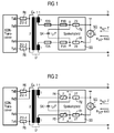
- FIG. 1 shows such a basic access connection.
- the supply of a local loop is via a switching side arranged power supply from -97 volts.
- the direct current internal resistance of the subscriber line, as defined at 1TR 216 should be included between the open circuit voltage and the voltage at maximum Supply current cause only a difference of 3V.
- the internal resistance In order to is the internal resistance with 3 V / 50 mA to a maximum of 60 ohms +/- component tolerances defined.
- the object of the invention is a further circuit arrangement for a supply circuit, on the one hand ETSI TS 102 080 or 1TR 216 and on the other hand a complete Protection against overvoltages and overcurrents ITU-T, K.20, Enhanced Test Levels.
- the invention is characterized by the features of claim 1 solved.
- the invention has the advantage that the circuit arrangement no more backups.
- the invention has the advantage that no failure the subscriber line circuit after a network contact with the a-wire or b-wire or both takes place.
- the invention has the advantage that no fuse replacement and therefore no exchange of subscriber line modules after contact with the network becomes necessary.
- the invention has the advantage that no repair costs attack.
- the invention has the advantage that ballasts, previously for the Enhanced Test Levels according to ITU-T, K.20, were necessary, avoided and therefore additional costs spared.
- the invention has the advantage that the overvoltage protection for lightning and induction voltages from power grids was significantly improved.
- a feed circuit a switching-side subscriber line circuit displayed.
- This supply circuit SS is the input side with a, for example -97 volts generating, voltage source SQ connected. Due to the earth-symmetrical line characteristic the subscriber line is the supply circuit to the connection point A or B with a resistor R1, R2 dimensioned by about 29 ohms.
- On a hybrid circuit trained feed circuit is in series with the DC resistors R1, R2 each have a first fuse F1A, F1B arranged.
- a feed bridge capacitor SK Between the connection points A, B is a capacitive element, a feed bridge capacitor SK, arranged.
- the feed bridge capacitor SK bypasses alternating current the DC resistors R1, R2, so they neither the AC-moderate internal resistance still influence reduce the bridgeable cable length of the connecting cable.
- the outputs of the supply circuit are each a second Fuse F2A, F2B, each with a connection of two arranged on the secondary side windings of a transformer U connected. These secondary-side transformer windings point each have a resistance of about 1 ohms.
- the respectively other connections of the secondary-side transformer windings are connected to the connection points a, b, to which the connecting cable connected to the subscriber.
- the first fuse F1A, F1B and the second fuse F2A, F2B are arranged in the cable run between A, a or B, b, so after triggering a backup of the feedbridge capacitor SK of the overvoltage applied between a and b is separated. This allows the use of capacitors with lower voltage requirements.
- the primary-side Transformer winding is via resistors R5, R6, for example with the transmitter outputs TxA, TxB of the ISDN transceiver connected.
- the resistors R5, R6 serve for two-wire four-wire implementation the transmission signals.
- the receive and receive signal is picked up by the receiver at the input RxA, RxB the received signal at these resistors.
- the likewise returned transmission signal is transmitted by the receiver eliminates the echo cancellation method.
- the dimensions of R5, R6 were the resistances of the transformer windings with a total of 4 ohms taken into account the terminals a, b the required AC resistance Z to achieve.
- FIG. 2 shows an exchange-side subscriber line circuit, according to that shown in Fig. 1, reproduced.
- the first fuse F1A, F1B and the second fuse F2A, F2B by a fuse element R3, R4 replaced both between A, a and B, b.
- This fuse element R3, R4 can be used in hybrid technology built-in power supply can be integrated.
- This security element R3, R4 assumes the task of the mediation side Subscriber connection against overvoltages and overcurrents, especially against overcurrents, which are at touch of the Connecting cable with mains voltages of 230 volts arise, to protect.
- the fuse element is shown in Fig. 2 of a third and fourth resistor R3, R4 formed, also called PTC thermistor referred to as.
- This PTC thermistor has a positive temperature coefficient on and is therefore also called PTC resistor designated.
- the value of the resistor R3, R4 is as small as possible so that he, too, in connection with his tolerance, one minimum influence on the characteristics and properties the overall circuit has. On the other hand you can very small values due to the low self-heating in case of overload, no longer fulfill their safety function. For this reason, the PTC resistor is with the feed resistor thermally coupled closely, hence the PTC resistance despite its small value by foreign warming its Fuse function fulfilled.
- a PTC resistor for example in polyswitch technology with 2 ohms, as a partial value of the total permissible sum resistance used by 30 ohms.
- the feed resistor R1, R2 is on the one hand by the sum resistance of 30 ohms and on the other hand dimensioned by the required symmetry of the supply circuit and is 27 ohms each.
- the PTC resistor is in place of the one previously used first fuse in the cable run from point A or B for connection a or b.
- This PTC resistor can either in the immediate vicinity, next to or at the back of the associated feed resistor R1, R2 are arranged.
- the thermal coupling continues to bring the advantage with it, that even at low currents such. at 0.5 A of the PTC resistor is heated and thereby its resistance value Increased so that the backup function is fulfilled becomes.
- the thermal coupling brings the additional Advantage with it, that smaller resistance values for the third and fourth resistor R3, R4 are selectable and thus its influence on all features of the local loop could be further minimized.
- the invention brings the advantage with it, that with it a reversible protection of the Circuit arrangement is implemented.
- the invention brings the advantage with it that no repair or no replacement of fuses after the power has been touched Has.
Landscapes
- Engineering & Computer Science (AREA)
- Computer Networks & Wireless Communication (AREA)
- Emergency Protection Circuit Devices (AREA)
Applications Claiming Priority (2)
| Application Number | Priority Date | Filing Date | Title |
|---|---|---|---|
| DE2003156497 DE10356497A1 (de) | 2003-12-03 | 2003-12-03 | Schaltungsanordnung zum Schutz gegen Überspannungen und Überströme |
| DE10356497 | 2003-12-03 |
Publications (2)
| Publication Number | Publication Date |
|---|---|
| EP1538864A2 true EP1538864A2 (fr) | 2005-06-08 |
| EP1538864A3 EP1538864A3 (fr) | 2008-06-25 |
Family
ID=34442422
Family Applications (1)
| Application Number | Title | Priority Date | Filing Date |
|---|---|---|---|
| EP04106149A Withdrawn EP1538864A3 (fr) | 2003-12-03 | 2004-11-29 | Ensemble circuit pour protéger contre surtensions et surintensités |
Country Status (2)
| Country | Link |
|---|---|
| EP (1) | EP1538864A3 (fr) |
| DE (1) | DE10356497A1 (fr) |
Family Cites Families (3)
| Publication number | Priority date | Publication date | Assignee | Title |
|---|---|---|---|---|
| SE466178B (sv) * | 1990-05-07 | 1992-01-07 | Ericsson Telefon Ab L M | Oeverspaennings- och oeverstroemsskydd foer ett linjeoeverdrag |
| US5721773A (en) * | 1995-03-30 | 1998-02-24 | Lucent-Technologies Inc. | Lightning protected maintenance termaination unit |
| DE19822760A1 (de) * | 1998-05-20 | 1999-11-25 | Siemens Ag | Netzabschlußeinrichtung mit Erdungsanschluß für digitale Kommunikationsnetze |
-
2003
- 2003-12-03 DE DE2003156497 patent/DE10356497A1/de not_active Withdrawn
-
2004
- 2004-11-29 EP EP04106149A patent/EP1538864A3/fr not_active Withdrawn
Also Published As
| Publication number | Publication date |
|---|---|
| EP1538864A3 (fr) | 2008-06-25 |
| DE10356497A1 (de) | 2005-07-14 |
Similar Documents
| Publication | Publication Date | Title |
|---|---|---|
| DE69103813T2 (de) | Überspannungs- und Überstromschutzschaltung. | |
| EP0668706B1 (fr) | Terminal de réseau | |
| DE69922416T2 (de) | Verfahren und vorrichtung die kopplung analoger teilnehmerleitungen in einem hausnetzwerk | |
| DE3850201T2 (de) | Leitungsschnittstellenschaltung. | |
| DE2808737A1 (de) | Schnittstelleneinrichtung, insbesondere teilnehmerschaltung fuer fernsprechanlagen | |
| EP0026411B1 (fr) | Circuit pour déterminer l'état d'occupation d'une ligne d'abonné dans des centraux téléphoniques | |
| DE69836205T2 (de) | Filtervorrichtung | |
| DE112018003859T5 (de) | Rückleistungseinspeisungs-leistungsversorgungseinrichtung und verfahren | |
| DE60100578T2 (de) | Vermittlungsschnittstelletechniken für digitalen Teilnehmerleitungen | |
| EP1538864A2 (fr) | Ensemble circuit pour protéger contre surtensions et surintensités | |
| DE10045015B4 (de) | Vorrichtung und Verfahren zur Regelung einer SLIC-Versorgungsspannung | |
| DE10140357A1 (de) | Telefonsystem mit regelbarer Klingelspannung | |
| DE602004012277T2 (de) | Benutzeranschluss-Testvorrichtung und Breitband- und Schmalband-Kommunikationssystem | |
| DE19758273B4 (de) | Notspeisefähige Stromversorgung für ISDN-Endsysteme | |
| DE2939008C2 (de) | Schaltungsanordnung für eine Teilnehmeranschlußschaltung eines elektronischen Vermittlungssystems | |
| DE2501651C2 (de) | Schaltungsanordnung zum Überspannungsschutz von elektronischen Koppelfeldern | |
| DE10240815B4 (de) | Verfahren zum Einstellen eines Rufsignalstroms in einer Teilnehmerleitung und Schaltungsanordnung | |
| DE2938982C2 (de) | Schaltungsanordnung für eine eigenprüfbare Teilnehmeranschlußschaltung mit Erkennung des Schaltzustandes einer Teilnehmerleitung | |
| DE3436903C2 (fr) | ||
| EP1437814B1 (fr) | Dispositif de protection contre les surtensions | |
| EP0589231B1 (fr) | Interface d'abonné pour raccordement d'une centrale privée à une centrale publique | |
| DE2305594B2 (de) | Schaltungsanordnung zur rufabschaltung in fernsprechvermittlungsanlagen | |
| EP1221775A1 (fr) | Méthode pour la transmission de signaux de télécommunication | |
| DE19604503B4 (de) | Schaltungsanordnung zur dezentralen Stromversorgung in Telekommunikations-Anlagen | |
| EP1281291B1 (fr) | Unite de terminaison reseau pour un terminal d'utilisateur et procede permettant de fournir, avec une optimisation de la puissance dissipee, une tension d'appel a un terminal d'utilisateur |
Legal Events
| Date | Code | Title | Description |
|---|---|---|---|
| PUAI | Public reference made under article 153(3) epc to a published international application that has entered the european phase |
Free format text: ORIGINAL CODE: 0009012 |
|
| AK | Designated contracting states |
Kind code of ref document: A2 Designated state(s): AT BE BG CH CY CZ DE DK EE ES FI FR GB GR HU IE IS IT LI LU MC NL PL PT RO SE SI SK TR |
|
| AX | Request for extension of the european patent |
Extension state: AL HR LT LV MK YU |
|
| RAP1 | Party data changed (applicant data changed or rights of an application transferred) |
Owner name: NOKIA SIEMENS NETWORKS GMBH & CO. KG |
|
| RAP3 | Party data changed (applicant data changed or rights of an application transferred) |
Owner name: NOKIA SIEMENS NETWORKS S.P.A. |
|
| RAP3 | Party data changed (applicant data changed or rights of an application transferred) |
Owner name: NOKIA SIEMENS NETWORKS GMBH & CO. KG |
|
| PUAL | Search report despatched |
Free format text: ORIGINAL CODE: 0009013 |
|
| AK | Designated contracting states |
Kind code of ref document: A3 Designated state(s): AT BE BG CH CY CZ DE DK EE ES FI FR GB GR HU IE IS IT LI LU MC NL PL PT RO SE SI SK TR |
|
| AX | Request for extension of the european patent |
Extension state: AL HR LT LV MK YU |
|
| AKX | Designation fees paid | ||
| STAA | Information on the status of an ep patent application or granted ep patent |
Free format text: STATUS: THE APPLICATION IS DEEMED TO BE WITHDRAWN |
|
| 18D | Application deemed to be withdrawn |
Effective date: 20081230 |
|
| REG | Reference to a national code |
Ref country code: DE Ref legal event code: 8566 |