EP1538831A1 - Kanalwählermodul - Google Patents
Kanalwählermodul Download PDFInfo
- Publication number
- EP1538831A1 EP1538831A1 EP04028144A EP04028144A EP1538831A1 EP 1538831 A1 EP1538831 A1 EP 1538831A1 EP 04028144 A EP04028144 A EP 04028144A EP 04028144 A EP04028144 A EP 04028144A EP 1538831 A1 EP1538831 A1 EP 1538831A1
- Authority
- EP
- European Patent Office
- Prior art keywords
- tuner
- channel
- aft voltage
- tuning
- channel selecting
- Prior art date
- Legal status (The legal status is an assumption and is not a legal conclusion. Google has not performed a legal analysis and makes no representation as to the accuracy of the status listed.)
- Withdrawn
Links
Images


Classifications
-
- H—ELECTRICITY
- H03—ELECTRONIC CIRCUITRY
- H03J—TUNING RESONANT CIRCUITS; SELECTING RESONANT CIRCUITS
- H03J5/00—Discontinuous tuning; Selecting predetermined frequencies; Selecting frequency bands with or without continuous tuning in one or more of the bands, e.g. push-button tuning, turret tuner
- H03J5/02—Discontinuous tuning; Selecting predetermined frequencies; Selecting frequency bands with or without continuous tuning in one or more of the bands, e.g. push-button tuning, turret tuner with variable tuning element having a number of predetermined settings and adjustable to a desired one of these settings
- H03J5/0245—Discontinuous tuning using an electrical variable impedance element, e.g. a voltage variable reactive diode, in which no corresponding analogue value either exists or is preset, i.e. the tuning information is only available in a digital form
-
- H—ELECTRICITY
- H03—ELECTRONIC CIRCUITRY
- H03J—TUNING RESONANT CIRCUITS; SELECTING RESONANT CIRCUITS
- H03J1/00—Details of adjusting, driving, indicating, or mechanical control arrangements for resonant circuits in general
- H03J1/0008—Details of adjusting, driving, indicating, or mechanical control arrangements for resonant circuits in general using a central processing unit, e.g. a microprocessor
- H03J1/0041—Details of adjusting, driving, indicating, or mechanical control arrangements for resonant circuits in general using a central processing unit, e.g. a microprocessor for frequency synthesis with counters or frequency dividers
-
- H—ELECTRICITY
- H03—ELECTRONIC CIRCUITRY
- H03J—TUNING RESONANT CIRCUITS; SELECTING RESONANT CIRCUITS
- H03J7/00—Automatic frequency control; Automatic scanning over a band of frequencies
- H03J7/02—Automatic frequency control
- H03J7/026—Means preventing a wrong working of the automatic frequency correction in case of fading or bad signal/noise ratio
-
- H—ELECTRICITY
- H04—ELECTRIC COMMUNICATION TECHNIQUE
- H04N—PICTORIAL COMMUNICATION, e.g. TELEVISION
- H04N21/00—Selective content distribution, e.g. interactive television or video on demand [VOD]
- H04N21/40—Client devices specifically adapted for the reception of or interaction with content, e.g. set-top-box [STB]; Operations thereof
- H04N21/41—Structure of client; Structure of client peripherals
- H04N21/426—Internal components of the client ; Characteristics thereof
- H04N21/42607—Internal components of the client ; Characteristics thereof for processing the incoming bitstream
- H04N21/4263—Internal components of the client ; Characteristics thereof for processing the incoming bitstream involving specific tuning arrangements, e.g. two tuners
-
- H—ELECTRICITY
- H04—ELECTRIC COMMUNICATION TECHNIQUE
- H04N—PICTORIAL COMMUNICATION, e.g. TELEVISION
- H04N21/00—Selective content distribution, e.g. interactive television or video on demand [VOD]
- H04N21/40—Client devices specifically adapted for the reception of or interaction with content, e.g. set-top-box [STB]; Operations thereof
- H04N21/43—Processing of content or additional data, e.g. demultiplexing additional data from a digital video stream; Elementary client operations, e.g. monitoring of home network or synchronising decoder's clock; Client middleware
- H04N21/438—Interfacing the downstream path of the transmission network originating from a server, e.g. retrieving encoded video stream packets from an IP network
- H04N21/4383—Accessing a communication channel
- H04N21/4384—Accessing a communication channel involving operations to reduce the access time, e.g. fast-tuning for reducing channel switching latency
-
- H—ELECTRICITY
- H04—ELECTRIC COMMUNICATION TECHNIQUE
- H04N—PICTORIAL COMMUNICATION, e.g. TELEVISION
- H04N5/00—Details of television systems
- H04N5/44—Receiver circuitry for the reception of television signals according to analogue transmission standards
-
- H—ELECTRICITY
- H04—ELECTRIC COMMUNICATION TECHNIQUE
- H04N—PICTORIAL COMMUNICATION, e.g. TELEVISION
- H04N5/00—Details of television systems
- H04N5/44—Receiver circuitry for the reception of television signals according to analogue transmission standards
- H04N5/50—Tuning indicators; Automatic tuning control
-
- H—ELECTRICITY
- H03—ELECTRONIC CIRCUITRY
- H03J—TUNING RESONANT CIRCUITS; SELECTING RESONANT CIRCUITS
- H03J5/00—Discontinuous tuning; Selecting predetermined frequencies; Selecting frequency bands with or without continuous tuning in one or more of the bands, e.g. push-button tuning, turret tuner
- H03J5/02—Discontinuous tuning; Selecting predetermined frequencies; Selecting frequency bands with or without continuous tuning in one or more of the bands, e.g. push-button tuning, turret tuner with variable tuning element having a number of predetermined settings and adjustable to a desired one of these settings
- H03J5/0245—Discontinuous tuning using an electrical variable impedance element, e.g. a voltage variable reactive diode, in which no corresponding analogue value either exists or is preset, i.e. the tuning information is only available in a digital form
- H03J5/0254—Discontinuous tuning using an electrical variable impedance element, e.g. a voltage variable reactive diode, in which no corresponding analogue value either exists or is preset, i.e. the tuning information is only available in a digital form the digital values being transfered to a D/A converter
- H03J5/0263—Discontinuous tuning using an electrical variable impedance element, e.g. a voltage variable reactive diode, in which no corresponding analogue value either exists or is preset, i.e. the tuning information is only available in a digital form the digital values being transfered to a D/A converter the digital values being held in an auxiliary non erasable memory
-
- H—ELECTRICITY
- H03—ELECTRONIC CIRCUITRY
- H03J—TUNING RESONANT CIRCUITS; SELECTING RESONANT CIRCUITS
- H03J5/00—Discontinuous tuning; Selecting predetermined frequencies; Selecting frequency bands with or without continuous tuning in one or more of the bands, e.g. push-button tuning, turret tuner
- H03J5/02—Discontinuous tuning; Selecting predetermined frequencies; Selecting frequency bands with or without continuous tuning in one or more of the bands, e.g. push-button tuning, turret tuner with variable tuning element having a number of predetermined settings and adjustable to a desired one of these settings
- H03J5/0245—Discontinuous tuning using an electrical variable impedance element, e.g. a voltage variable reactive diode, in which no corresponding analogue value either exists or is preset, i.e. the tuning information is only available in a digital form
- H03J5/0272—Discontinuous tuning using an electrical variable impedance element, e.g. a voltage variable reactive diode, in which no corresponding analogue value either exists or is preset, i.e. the tuning information is only available in a digital form the digital values being used to preset a counter or a frequency divider in a phase locked loop, e.g. frequency synthesizer
- H03J5/0281—Discontinuous tuning using an electrical variable impedance element, e.g. a voltage variable reactive diode, in which no corresponding analogue value either exists or is preset, i.e. the tuning information is only available in a digital form the digital values being used to preset a counter or a frequency divider in a phase locked loop, e.g. frequency synthesizer the digital values being held in an auxiliary non erasable memory
Definitions
- the invention relates to a channel selecting unit in electronic equipment provided with a tuner such as a TV (television) receiver, a VTR (Video Tape Recorder) having a built-in tuner, and the like.
- a tuner such as a TV (television) receiver, a VTR (Video Tape Recorder) having a built-in tuner, and the like.
- JP 7-7391A in an automatic search tuning system for automatically deciding a tuning point based on a synchronous signal of a received TV signal and an AFT signal by automatically varying a tuning voltage to be applied to a turner, a plurality of standard values for deciding the presence or absence of the synchronous signal are provided, which standard values can be selected by operating a switching key
- JP 2001-119643A in the case where a received frequency is changed by varying a channel selecting voltage of a tuner based on a channel switching instruction, a microcomputer confirms stability of anAGC voltage and an AFT voltage, then checks as to whether the AFT voltage is the same as a standard voltage value or not, and retains a receiving state at that time, thereby ending a channel selecting operation.
- JP 2003-179824A in the case where a synchronization detecting signal outputted from a video recorder represents the presence of a synchronous signal, a value of an IF-AGC voltage generated in a tuner and channel information instructed by a tuning instruction signal are allowed to correspond to each other and stored.
- the AGC voltage is prone to vary owing to an external factor and is unstable, which renders an accurate channel selecting operation difficult.
- the channel selecting unit is characterized in comprising a tuner for outputting an intermediate frequency based on a tuning instruction signal corresponding to a channel, a VIF circuit for amplifying the intermediate frequency signal outputted from the tuner and outputting an AFT voltage, a video signal processing circuit for separating a synchronous signal from the amplified intermediately frequency signal outputted from the VIF circuit and outputting the synchronous signal, and a control circuit for outputting the tuning instruction signal to the tuner and subjecting the tuner to an AFT control based on the AFT voltage, wherein the control circuit is comprised of synchronization detecting means for detecting the presence or absence of synchronization based on the synchronous signal, storage means for storing therein tuning frequency data and an AFT voltage value for every channel when the synchronization detecting means detects the presence of synchronization and the AFT voltage falling within a predetermined range, and channel select control means for reading out the tuning frequency data and the AFT voltage value of a pertinent turner from
- the channel selecting unit is characterized in comprising a plurality of tuners each outputting an intermediate frequency based on a tuning instruction signal corresponding to a channel, a plurality of VIF circuits each amplifying an intermediate frequency signal outputted from each tuner and outputting an AFT voltage, a video signal processing circuit for separating a synchronous signal from the amplified intermediate frequency signal outputted from each VIF circuit and outputting the synchronous signal, and a control circuit for outputting the tuning instruction signal to each tuner and subjecting each tuner to an AFT control based on the AFT voltage, wherein the control circuit is comprised of synchronization detecting means for detecting the presence or absence of synchronization based on the synchronous signal which is separated from the intermediate frequency signal outputted from a specified tuner, storage means for storing therein tuning frequency data and an AFT voltage value for every channel when the synchronization detecting means detects the presence of synchronization and the AFT voltage falling within a predetermined range, and channel select control means for reading out the
- the channel select control means is characterized in implementing the channel selecting operation until the AFT voltage reaches a predetermined range by controlling the frequency in such a manner that it gradually increases the frequency beginning with frequency data which is lower than the tuning frequency data read out from the storage means by a predetermined frequency.
- the channel selecting unit having the above mentioned configuration, since the tuning frequency data and the AFT voltage value are stored for every channel when the synchronization detecting means detects the presence of synchronization and the AFT voltage falling within the predetermined range, and the tuning frequency data and the AFT voltage value of the pertinent channel are read out from the storage means when the channel is subsequently switched, thereby implementing the channel selecting operation. Accordingly, once the tuning frequency data and the AFT voltage value are stored in the storage means for every channel, the channel selecting operation can be implemented without detecting synchronization so that the channel selecting operation can be implemented in a short time. Further, since the channel selecting operation is implemented by use of the AFT voltage value which is not susceptible to an external factor, a stable and accurate channel selecting operation can be implemented.
- the tuning frequency data and the AFT voltage value are stored in the storage means for every channel, while at the time of switching of the channel relative to the tuner other than the specified tuner, the tuning frequency data and the AFT voltage value of the pertinent channel are read out from the storage means, thereby implementing the channel selecting operation, so that the detection of synchronization relative to the tuner other than the specified tuner is not needed, thereby dispensing with the synchronization detecting circuit and the detection processing. Accordingly, the circuit configuration and the process can be simplified, and an accurate channel selecting operation can be implemented in a short time.
- a channel selecting operation of the tuner for viewing can be implemented by use of tuning frequency data and an AFT voltage value which are determined by the tuner for recording picture, so that the channel selecting operation by the tuner for viewing can be implemented in a short time, thereby simplifying the circuit configuration and downsizing the channel selecting unit per se.
- the channel select control means implements the channel selecting operation until the AFT voltage reaches a predetermined range by controlling the frequency in such a manner that it gradually increases the frequency beginning with frequency data which is lower than the tuning frequency data read out from the storage means by a predetermined frequency, even if the actual tuning frequency is deviated from the stored data, the channel selecting operation can be surely implemented.
- Fig. 1 is an entire block diagram of a video display unit provided with the embodiment of the invention.
- the video display unit comprises a picture recording and playback portion 1 for recording a picture and play backing the recorded picture upon reception of a TV broadcast signal, a receiver portion 2 for viewing a TV broadcast program, a control portion 3 for controlling the entire video display unit, a storage portion 4 for storing a program and data necessary for implementing the control, a video display processing circuit 5 for implementing a process in such a manner that it receives a video signal from the picture recording and playback portion 1 or the receiver portion 2 and displays the video signal on a CRT 6, and an operation information input portion 7 for receiving an operation signal issued by a remote controller 8 when an operator operates the remote controller 8.
- the picture recording and playback portion 1 is comprised of a tuner 10 for amplifying a frequency signal of an intended channel from a TV broadcast signal received by an antenna to output it as an intermediate frequency signal (frequency is 58.75 MHz), a VIF circuit 11 connected to the tuner 10 for amplifying the intermediate frequency signal, a detection circuit 12 connected to the VIF circuit 11 for fetching a video signal from the intermediate frequency signal, and a video information processing portion 13 connected to the detection circuit 12 for processing the video signal to output the processed video signal to a recorded picture playback portion 14.
- a tuner 10 for amplifying a frequency signal of an intended channel from a TV broadcast signal received by an antenna to output it as an intermediate frequency signal (frequency is 58.75 MHz)
- VIF circuit 11 connected to the tuner 10 for amplifying the intermediate frequency signal
- a detection circuit 12 connected to the VIF circuit 11 for fetching a video signal from the intermediate frequency signal
- a video information processing portion 13 connected to the detection circuit 12 for processing the video signal to output the processed
- the VIF circuit 11 outputs an AFT voltage necessary for keeping an oscillation frequency of the tuner 10 in a stable state to the control portion 3, and the video information processing portion 13 receives video information which is play backed by the recorded picture playback portion 14 and transmits it to the video display processing circuit 5, and also separates a synchronous signal from the video signal and outputs it to the control portion 3.
- the receiver portion 2 is comprised of a tuner 20, a VIF circuit 21 and a detection circuit 22 like the tuner 10, the VIF circuit 11 and the detection circuit 12, respectively, of the picture recording and playback portion 1, wherein a video signal outputted from the detection circuit 22 is to be inputted to the video display processing circuit 5.
- the control portion 3 is comprised of an AFT voltage detecting portion 30 for receiving the AFT voltages outputted from the VIF circuit 11 and the VIF circuit 21, a pulse counter 31 for counting the synchronous signal upon reception of the same synchronous signal outputted from the video information processing portion 13, a synchronization detecting potion 33 for detecting the presence or absence of synchronization based on a counted value of the pulse counter 31, a channel selecting portion 32 for outputting a tuning instruction signal corresponding to a selected channel to the tuner 10 or the tuner 20, and receiving detection signals from the AFT voltage detecting portion 30 and the synchronization detecting potion 33, thereby controlling the tuner to implement a channel selecting operation, a channel decision portion 35 for deciding a channel upon reception of the operation signal outputted from the operation information input portion 7, and a processing portion 34 for outputting information needed for selecting the channel to the channel selecting portion 32, and allowing the tuning frequency data and the AFT voltage value outputted from the channel selecting portion 32 to be stored in the storage portion 4 together with channel information.
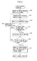
- Fig. 2 is a flowchart showing processes of a preset operation for implementing the channel selecting operation first.
- central frequency data f c of one channel is first read out (S100).
- Central frequencies of respective channels are predetermined and the central frequencies of all the channels are stored in the storage portion 4 as a data table.
- a central frequency (93MHz) of the first channel is read out by the processing portion 34.
- the processing portion 34 transmits the readout central frequency data to the channel selecting portion 32, and the channel selecting portion 32 transmits a tuning instruction signal to the tuner 10 based on the same data (S101).
- the tuner 10 amplifies the pertinent central frequency signal based on the tuning instruction signal and outputs an intermediate frequency signal to the VIF circuit 11, and the signal is transmitted from the VIF circuit 11 to the video information processing portion 13 through the detection circuit 12, while the synchronous signal is separated in the video information processing portion 13, and it is inputted to the pulse counter 31 (S102).
- the pulse counter 31 counts, for example, a horizontal synchronous signal and the synchronization detecting potion 33 checks as to whether the counted value issued from the pulse counter 31 is not less than the standard value or not in a predetermined time (S103).
- the synchronization detecting potion 33 detects the presence or absence of synchronization based on the counted value issued from the pulse counter 31, and transmits a detection signal representing the absence of synchronization to the channel selecting portion 32 if the counted value is not more than the standard value.
- the channel selecting portion 32 adds a predetermined frequency to and subtracts the predetermined frequency from the central frequency upon reception of the detection signal representing the absence of synchronization (S104), and the channel selecting portion 32 transmits the corrected frequency data again to the tuner 10.
- the frequency data is corrected until the counted value of the pulse counter 31 exceeds the standard value.
- the channel selecting portion 32 receives data relating to the AFT voltage of the VIF circuit 11 from the AFT voltage detecting portion 30 (S105). Then, the channel selecting portion 32 checks as to whether the AFT voltage value falls within a predetermined range (S106).
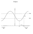
- Fig. 4 is a graph showing a relationship between the AFT voltage and the frequency wherein a horizontal axis shows the frequency while the vertical axis shows the AFT voltage. The AFT voltage varies so as to draw a sine wave relative to the frequency, however the graph shows a part of the sine wave.
- the AFT voltage is set, as shown in Fig.
- step S106 it is checked as to whether the AFT voltage falls within the range defined by the upper limit voltage Vmax and the lower limit voltage Vmin, and if the AFT voltage falls beyond this range, the frequency data is corrected in step S104, then the tuning operation is controlled again.
- the channel selecting portion 32 transmits the tuning frequency data f 1 and an AFT voltage value V 0 at the time of decision to the processing portion 34, and the processing portion 34 allows the tuning frequency data f 1 and the AFT voltage value V 0 to be stored in the storage portion 4 together with a channel number (S107).
- the preset operation is implemented by use of the tuner 10 alone but not implemented by use of the tuner 20.
- the channel switching operation is implemented by an operator who selectively operate the channel using the remote controller 8, and the operation signal is transmitted to the operation information input portion 7.
- the operation signal received by the operation information input portion 7 is transmitted to the processing portion 34 after the selected channel information is decided in a channel decision portion 35.
- Fig. 3 is a flowchart showing processes in a channel switch processing which is implemented based on the channel information.
- the processing portion 34 reads out the tuning frequency data f 1 and the AFT voltage value V 0 corresponding to the channel information from the storage portion 4 (S200).
- the tuning frequency data f 1 and the AFT voltage value V 0 thus read out by the processing portion 34 are transmitted to the channel selecting portion 32, where a frequency data f n is calculated by subtracting a predetermined frequency f 2 from the tuning frequency data f 1 (S201).
- the tuning instruction signal is transmitted to the tuner 20 based on the calculated frequency data f n .
- the AFT voltage outputted from the VIF circuit 21 is detected by the AFT voltage detecting portion 30 by implementing the tuning operation in the tuner 20 (S203). Then it is checked as to whether the AFT voltage is equal to the AFT voltage value V 0 or not (S204). If the tuning operation is started with the frequency data f n in the tuner 20, since the frequency data f n is smaller than the tuning frequency data f 1 owing to the existence of the relationship between the AFT voltage and the frequency as shown in Fig. 4, the AFT voltage is detected to be smaller than the AFT voltage value V 0 .
- the tuning operation is implemented by the tuner 20 while the frequency data f n is increased so as to allow the detected AFT voltage to approach the AFT voltage value V 0 , and it is considered that synchronization is effected at the time when the detected AFT voltage is equal to the AFT voltage value V 0 , thereby ending the channel selecting operation.
- the predetermined frequency f 2 is set at a value not more than 2 MHz which is a range where the deviation of the AFT voltage can be corrected.
- the channel switch processing of the tuner 20 can be implemented without detecting synchronization, the processing can be simplified and implemented in a short time and also the channel selecting operation can be reliably implemented.
- the tuning operation is started with the frequency data f n obtained by subtracting the predetermined frequency f 2 from the tuning frequency data f 1 , the turning operation may be implemented using the tuning frequency data f 1 as it is. In this case, the processing can be further simplified.
- the channel switch processing can be implemented by the tuner 20
- the channel switch processing of the tuner 10 can be likewise implemented in a short time by use of the tuning frequency data f 1 and the AFT voltage value V 0 which are stored by the preset operation.
Landscapes
- Engineering & Computer Science (AREA)
- Multimedia (AREA)
- Signal Processing (AREA)
- Computer Hardware Design (AREA)
- Microelectronics & Electronic Packaging (AREA)
- Channel Selection Circuits, Automatic Tuning Circuits (AREA)
Applications Claiming Priority (2)
| Application Number | Priority Date | Filing Date | Title |
|---|---|---|---|
| JP2003400992 | 2003-12-01 | ||
| JP2003400992A JP2005167434A (ja) | 2003-12-01 | 2003-12-01 | 選局装置 |
Publications (1)
| Publication Number | Publication Date |
|---|---|
| EP1538831A1 true EP1538831A1 (de) | 2005-06-08 |
Family
ID=34463917
Family Applications (1)
| Application Number | Title | Priority Date | Filing Date |
|---|---|---|---|
| EP04028144A Withdrawn EP1538831A1 (de) | 2003-12-01 | 2004-11-26 | Kanalwählermodul |
Country Status (3)
| Country | Link |
|---|---|
| US (1) | US20050117072A1 (de) |
| EP (1) | EP1538831A1 (de) |
| JP (1) | JP2005167434A (de) |
Families Citing this family (4)
| Publication number | Priority date | Publication date | Assignee | Title |
|---|---|---|---|---|
| EP1926306A1 (de) * | 2006-11-24 | 2008-05-28 | Thomson Licensing | Verfahren und Vorrichtung für automatische Feinabstimmung basierend auf Synchronisationserkennung |
| US20080271108A1 (en) * | 2007-04-24 | 2008-10-30 | Wanwen Shi | Satellite and cable ready TV display device |
| JP2015162776A (ja) * | 2014-02-27 | 2015-09-07 | 船井電機株式会社 | テレビ放送受信装置およびテレビ放送受信装置の受信方法 |
| US9924233B2 (en) * | 2015-04-22 | 2018-03-20 | The Directv Group, Inc. | Systems and methods for controlling a single-wire multiswitch device |
Citations (5)
| Publication number | Priority date | Publication date | Assignee | Title |
|---|---|---|---|---|
| US4326220A (en) * | 1979-09-05 | 1982-04-20 | Sony Corporation | Television receiver |
| US4870492A (en) * | 1986-07-31 | 1989-09-26 | Sony Corporation | Television receiver having automatically programmable skip channel list |
| EP0396103A2 (de) * | 1989-05-01 | 1990-11-07 | Kabushiki Kaisha Toshiba | Kanalwählendes Gerät |
| US5034819A (en) * | 1989-06-20 | 1991-07-23 | Kabushiki Kaisha Toshiba | Channel selecting apparatus and method used in a television receiving apparatus and capable of memorizing channel data |
| US6359580B1 (en) * | 1997-03-18 | 2002-03-19 | Thomson Licensing S.A. | Multiple source keypad channel entry system and method |
Family Cites Families (10)
| Publication number | Priority date | Publication date | Assignee | Title |
|---|---|---|---|---|
| US4254506A (en) * | 1979-05-30 | 1981-03-03 | Rca Corporation | Channel identification apparatus useful in a multiband sweep type tuning system |
| KR100206781B1 (ko) * | 1996-04-24 | 1999-07-01 | 구자홍 | 텔레비젼수상기의 초고속 채널기억 장치 및 방법 |
| KR100309099B1 (ko) * | 1997-06-21 | 2001-12-15 | 윤종용 | 채널 선국방법 및 장치 |
| GB2343815B (en) * | 1998-11-12 | 2003-10-22 | Sony Uk Ltd | Digital receiver |
| US6525779B1 (en) * | 1998-12-21 | 2003-02-25 | Funai Electric Co. Ltd. | Television receiver for receiving two different broadcast forms |
| US6985188B1 (en) * | 1999-11-30 | 2006-01-10 | Thomson Licensing | Video decoding and channel acquisition system |
| US6519011B1 (en) * | 2000-03-23 | 2003-02-11 | Intel Corporation | Digital television with more than one tuner |
| US6804824B1 (en) * | 2000-06-30 | 2004-10-12 | Microsoft Corporation | Systems and methods using multiple tuners |
| US6714264B1 (en) * | 2000-08-31 | 2004-03-30 | Matsushita Electric Industrial Co., Ltd. | Digital television channel surfing system |
| US7142255B2 (en) * | 2003-10-08 | 2006-11-28 | Silicon Laboratories Inc. | Transport stream and channel selection system for digital video receiver systems and associated method |
-
2003
- 2003-12-01 JP JP2003400992A patent/JP2005167434A/ja active Pending
-
2004
- 2004-11-26 EP EP04028144A patent/EP1538831A1/de not_active Withdrawn
- 2004-11-30 US US11/000,312 patent/US20050117072A1/en not_active Abandoned
Patent Citations (5)
| Publication number | Priority date | Publication date | Assignee | Title |
|---|---|---|---|---|
| US4326220A (en) * | 1979-09-05 | 1982-04-20 | Sony Corporation | Television receiver |
| US4870492A (en) * | 1986-07-31 | 1989-09-26 | Sony Corporation | Television receiver having automatically programmable skip channel list |
| EP0396103A2 (de) * | 1989-05-01 | 1990-11-07 | Kabushiki Kaisha Toshiba | Kanalwählendes Gerät |
| US5034819A (en) * | 1989-06-20 | 1991-07-23 | Kabushiki Kaisha Toshiba | Channel selecting apparatus and method used in a television receiving apparatus and capable of memorizing channel data |
| US6359580B1 (en) * | 1997-03-18 | 2002-03-19 | Thomson Licensing S.A. | Multiple source keypad channel entry system and method |
Also Published As
| Publication number | Publication date |
|---|---|
| US20050117072A1 (en) | 2005-06-02 |
| JP2005167434A (ja) | 2005-06-23 |
Similar Documents
| Publication | Publication Date | Title |
|---|---|---|
| EP0536553B1 (de) | Fernsehempfänger | |
| JP2891273B2 (ja) | 信号スイッチング装置 | |
| KR100406985B1 (ko) | 자동선국 중에 선국된 채널을 표시하는 텔레비젼, 및 그의자동선국화면 표시방법 | |
| USRE41707E1 (en) | Digital broadcasting receiver and method of controlling the same | |
| US5477277A (en) | Apparatus and method for controlling the muting of sound and the display of audio information on a television receiver | |
| JPH0775015A (ja) | テレビチャンネル切換装置 | |
| EP1538831A1 (de) | Kanalwählermodul | |
| EP1765009A2 (de) | Fernsehempfänger | |
| KR0113153Y1 (ko) | 무신호시 저장화면출력기능을 갖춘 비디오비전 | |
| EP1592241B1 (de) | Digitalrundfunkempfänger für Nachrichtensatelliten | |
| JP3339389B2 (ja) | 映像機器 | |
| KR100525864B1 (ko) | 입력포트 선택 절환방법 | |
| JP3019328B2 (ja) | テレビジョン受像機 | |
| KR100500249B1 (ko) | 텔레비전 수신기 및 그 자동채널설정방법 | |
| KR100229543B1 (ko) | 비디오 카세트 레코더의 채널 설정 장치 및 방법 | |
| KR19980040699A (ko) | 다수의 외부신호 입력단자를 가진 텔레비젼 수상기에서 외부신호 입력시 자동 선택장치 및 그 방법 | |
| KR0181017B1 (ko) | 텔레비전수상기의 vcr 플레이시 채널자동절환방법 | |
| KR100220176B1 (ko) | 멀티 tvcr의 비디오 신호 처리 장치 | |
| JP3388520B2 (ja) | ダイバーシティ受信装置 | |
| KR100187953B1 (ko) | 텔레비디오수상기의 예약녹화설정후 비디오시청시 경고방법 | |
| JP2566999Y2 (ja) | 自動選局回路 | |
| KR19980017762A (ko) | 중요화면 기록/재생장치 | |
| KR19980029603A (ko) | 상, 하, 좌, 우 모서리 선택에 의한 tv 화면 위치 이동장치 및 그 방법 | |
| JPH08168035A (ja) | モニタ装置 | |
| KR20000011605U (ko) | 브이시알의 티브이방송 확인장치 |
Legal Events
| Date | Code | Title | Description |
|---|---|---|---|
| PUAI | Public reference made under article 153(3) epc to a published international application that has entered the european phase |
Free format text: ORIGINAL CODE: 0009012 |
|
| AK | Designated contracting states |
Kind code of ref document: A1 Designated state(s): AT BE BG CH CY CZ DE DK EE ES FI FR GB GR HU IE IS IT LI LU MC NL PL PT RO SE SI SK TR |
|
| AX | Request for extension of the european patent |
Extension state: AL HR LT LV MK YU |
|
| 17P | Request for examination filed |
Effective date: 20050704 |
|
| AKX | Designation fees paid |
Designated state(s): DE FR GB IT |
|
| 17Q | First examination report despatched |
Effective date: 20071123 |
|
| STAA | Information on the status of an ep patent application or granted ep patent |
Free format text: STATUS: THE APPLICATION IS DEEMED TO BE WITHDRAWN |
|
| 18D | Application deemed to be withdrawn |
Effective date: 20080404 |