EP1538729B1 - Bürstenhalter für einen elektrischen Motor - Google Patents
Bürstenhalter für einen elektrischen Motor Download PDFInfo
- Publication number
- EP1538729B1 EP1538729B1 EP04257532A EP04257532A EP1538729B1 EP 1538729 B1 EP1538729 B1 EP 1538729B1 EP 04257532 A EP04257532 A EP 04257532A EP 04257532 A EP04257532 A EP 04257532A EP 1538729 B1 EP1538729 B1 EP 1538729B1
- Authority
- EP
- European Patent Office
- Prior art keywords
- cage
- brush
- barbs
- hole
- clip
- Prior art date
- Legal status (The legal status is an assumption and is not a legal conclusion. Google has not performed a legal analysis and makes no representation as to the accuracy of the status listed.)
- Expired - Lifetime
Links
- 238000000034 method Methods 0.000 claims description 9
- 238000003780 insertion Methods 0.000 claims description 8
- 230000037431 insertion Effects 0.000 claims description 8
- 239000012212 insulator Substances 0.000 claims description 8
- 230000000712 assembly Effects 0.000 claims description 6
- 238000000429 assembly Methods 0.000 claims description 6
- 239000011810 insulating material Substances 0.000 claims description 6
- 239000000463 material Substances 0.000 claims description 4
- 239000002184 metal Substances 0.000 claims description 3
- 238000000465 moulding Methods 0.000 claims description 3
- 229910001220 stainless steel Inorganic materials 0.000 claims description 3
- 239000010935 stainless steel Substances 0.000 claims description 3
- 239000004020 conductor Substances 0.000 claims description 2
- 229910001369 Brass Inorganic materials 0.000 description 6
- 239000010951 brass Substances 0.000 description 6
- 238000001816 cooling Methods 0.000 description 2
- 239000004033 plastic Substances 0.000 description 2
- 229920003023 plastic Polymers 0.000 description 2
- OKTJSMMVPCPJKN-UHFFFAOYSA-N Carbon Chemical compound [C] OKTJSMMVPCPJKN-UHFFFAOYSA-N 0.000 description 1
- 229910052799 carbon Inorganic materials 0.000 description 1
- 238000010276 construction Methods 0.000 description 1
- 230000017525 heat dissipation Effects 0.000 description 1
- 238000012986 modification Methods 0.000 description 1
- 230000004048 modification Effects 0.000 description 1
- 239000011347 resin Substances 0.000 description 1
- 229920005989 resin Polymers 0.000 description 1
- 238000000926 separation method Methods 0.000 description 1
- 238000009423 ventilation Methods 0.000 description 1
- 238000004804 winding Methods 0.000 description 1
Images


Classifications
-
- H—ELECTRICITY
- H02—GENERATION; CONVERSION OR DISTRIBUTION OF ELECTRIC POWER
- H02K—DYNAMO-ELECTRIC MACHINES
- H02K5/00—Casings; Enclosures; Supports
- H02K5/04—Casings or enclosures characterised by the shape, form or construction thereof
- H02K5/14—Means for supporting or protecting brushes or brush holders
- H02K5/143—Means for supporting or protecting brushes or brush holders for cooperation with commutators
- H02K5/148—Slidably supported brushes
-
- H—ELECTRICITY
- H01—ELECTRIC ELEMENTS
- H01R—ELECTRICALLY-CONDUCTIVE CONNECTIONS; STRUCTURAL ASSOCIATIONS OF A PLURALITY OF MUTUALLY-INSULATED ELECTRICAL CONNECTING ELEMENTS; COUPLING DEVICES; CURRENT COLLECTORS
- H01R39/00—Rotary current collectors, distributors or interrupters
- H01R39/02—Details for dynamo electric machines
- H01R39/38—Brush holders
- H01R39/385—Means for mechanical fixation of the brush holder
-
- H—ELECTRICITY
- H02—GENERATION; CONVERSION OR DISTRIBUTION OF ELECTRIC POWER
- H02K—DYNAMO-ELECTRIC MACHINES
- H02K5/00—Casings; Enclosures; Supports
- H02K5/04—Casings or enclosures characterised by the shape, form or construction thereof
- H02K5/16—Means for supporting bearings, e.g. insulating supports or means for fitting bearings in the bearing-shields
- H02K5/173—Means for supporting bearings, e.g. insulating supports or means for fitting bearings in the bearing-shields using bearings with rolling contact, e.g. ball bearings
- H02K5/1732—Means for supporting bearings, e.g. insulating supports or means for fitting bearings in the bearing-shields using bearings with rolling contact, e.g. ball bearings radially supporting the rotary shaft at both ends of the rotor
Definitions
- This invention relates to electric motors and in particular, to a brush holder assembly for a small electric motor.
- the brush tube requires means for fixing it within the hole in the insulator. This is usually in the form of a step which prevents the tube from being pressed in further and a raised finger which is resiliently deformed as the tube is being pressed in but snaps into a recess as the tube is fully inserted to prevent withdrawal.
- the brass tube is a precision assembly. If the tube's internal dimensions are too small, the brush will not slide and if it is too big, the brush will wobble within the tube causing sparking on the commutator leading to rapid wear of both brush and commutator. Also, the hole in the insulator must be tightly controlled so that the tube will be held snugly but not so tightly to deform the tube and catch the brush. Another disadvantage is that the snap finger is not very resilient and often does not rebound enough to adequately hold the tube in place. To overcome this problem, the recess for the finger is made bigger to ensure clearance between the finger and the edge of the recess but this allows axial movement of the brush tube which also leads to sparking under vibration.
- a commutator motor according to the preamble of claim 1 is known from the US-patent US 5,631,513 .
- the present invention overcomes these problems by providing a separate clip which grips both the insulator and the brush cage to prevent withdrawal of the brush cage.
- the present invention provides a commutator motor, including a stator, wound rotor, bearing bracket and at least two sets of brush gear, wherein each brush gear comprises a brush, a brush cage and a brush spring, the brush cage being fitted to a radial through hole in the bearing bracket for directing the brush towards the commutator characterised by a cage clip having a first set of barbs which engage and grip a wall of the through hole to prevent withdrawal of the clip from the through hole once inserted and a second set of barbs which engage and grip an outer surface of the brush cage to prevent withdrawal of the brush cage from the through hole.
- brush cage resiliently deforms the second set of barbs on insertion thereby ensuring good contact between the second set of barbs and the cage.
- the resilient deformation results in a lateral pretension on the cage reducing the lateral play between the cage and the through hole.
- the clip is U-shaped and straddles a wall of the through hole.
- clip has an outer limb bearing the first set of barbs and an inner limb bearing the second set of barbs.
- the outer limb is shorter than the inner limb and has an outwardly curved distal end.
- the first set of barbs is inwardly and rearwardly directed.
- the second set of barbs is outwardly and forwardly directed.
- At least some of the barbs are cut and raised projections.
- the clip is of a resilient conducting material.
- the material is stainless steel.
- the bearing bracket is of a moulded insulating material.
- the bearing bracket is a U-shaped stamped metal part having an insulator of moulding insulating material fitted to each leg, each insulator forming the through hole for receiving a respective brush cage.
- the present invention also provides a method of assembling a commutator motor having a stator, bearing bracket, a wound rotor and two sets of cage brush assemblies, the method including the steps of: fitting the rotor to the stator and bearing bracket and fitting the brush assemblies to a respective through hole in one of the bearing brackets, said fitting of the brush assemblies including the steps of: providing a cage clip having a first set of barbs and a second set of barbs, inserting the cage clip into the through hole so as to engage the first set of barbs with a wall of the through hole and to avoid engaging the second set of barbs with the wall of the through hole, inserting a brush cage into the through hole so as to resiliently deform the second set of barbs on insertion and to engage the second set of barbs on movement of the cage in the opposite direction, inserting a brush into the cage, inserting a brush spring into the cage to urge the brush into contact with the commutator and capturing the spring to remain in resilient contact with the brush.
- the clip is U-shaped and is pressed into the through hole so as to straddle the wall and is pressed in until a base of the U contacts the wall.
- the cage is provided with an external stopper and the cage is pressed into the through hole until the stopper contacts the bearing bracket.
- the method includes the step of using the resiliency of the deformed second set ot barbs to provide a lateral pretension on the brush cage to reduce lateral play of the cage within the through hole.
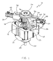
- the present invention will be illustrated by describing a preferred embodiment of the brush assembly as used in a universal motor as shown in Figure 1 .
- the universal motor 10 has a laminated stator core 12 supporting stator windings 14.
- a wound rotor 16, including a commutator 18 and a shaft 20 is located extending through the stator core 12.
- An output bearing bracket 22 is fixed to one axial end of the stator core.
- An input bearing bracket 24 is fixed to the other axial end of the stator core 12.
- the bearing brackets 22, 24 are fixed to the stator core 12 by bolts 25 which extend through holes in the brackets 22, 24 and through or along side the stator core 12. Both brackets 22, 24 support bearings in which the shaft 20 is journalled.
- the output bracket 22 is U-shaped and may include additional holes for mounting of the motor to an appliance.
- the input bracket 24 is also U-shaped and the commutator is located between the legs 26 of the input bracket. Each leg of the input bracket also has a radial hole 28 formed therethrough. Brush cages 30 are accommodated in the holes 28 for guiding carbon brushes 32 located within the cages into contact with the commutator 18.
- the input bracket 24 is a moulded resin article of a suitable engineering insulating plastics material such as "BMC”.
- the through hole 28 has a stepped profile as is common.
- a U-shaped clip 34 is placed over a lateral edge or wall 38 of the hole 28 such that one leg 36 of the clip extends along an inner surface of the wall 38 and the other leg 40 of the clip extends along an outer or second surface of the wall 38.
- the wall 38 is straddled and gripped by the clip 34.
- the brush cage 30 is a tube formed from brass sheet.
- the tube has a basic rectangular cross-section, to match the cross section of an associated brush, with the longer or major sides 50, 51 being stepped or curved to accommodate a brush spring 33 ( Fig. 4 ).
- the through hole 28 is similarly stepped to hold the brush cage 30 only by the edges of the long sides 50, 51.
- the short top side 52 of the brush cage is flat and the through hole 28 has a similar dimension except that the through hole may have an opening 56 along the middle of the top side to aid cooling of the brush and cage.
- the short bottom side 54 of the cage is flat but the bottom side of the through hole 28 is stepped to provide a clearance or passage way 58 along the middle of the bottom side for air flow to cool the brush 32 and cage 30.
- the cage 30 may have ventilation openings 60 ( Figures 1 , 3 ) along the top and bottom sides 52, 54 to aid cooling of the brush.
- the cage is held in the through hole essentially by the comers of the through hole 28. This is advantageous as the moulding process tolerances can be relaxed to allow warpage of the faces of the through hole 28 whereas the comers, being better supported by surrounding material is less likely to warp and is easier to control.
- a brush 32 is inserted into the cage followed by a brush spring 33.
- a flap 64 at the distal end of the cage 30 is then bent to close the end of the cage preventing removal of the spring and brush and providing a seat for the spring to bear against as it urges the brush towards the commutator. As shown in Fig.
- brush 32 may have an embedded shunt wire 31 which may pass through the spring 33 and terminate on a terminal 35 which prevents separation of the spring 33 so that the brush 12 and spring 33 is installed as a single unit with the shunt providing the electrical connection to the brush 33 via the terminal 35.
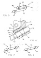
- the clip 34 is shown more clearly in Figure 5 .
- the long leg 36 of the clip has barbs 42 formed at its distal end region. Barbs 42 are outwardly and forwardly directed to avoid contact with the wall 38 of the through hole.
- the shorter leg 40 of the clip has an outwardly curved distal end 48 to aid insertion of the clip.
- the distal end region also has barbs 44. Barbs 44 are inwardly and rearwardly directed. The barbs 44 make contact with the outer surface of wall 38 of the through hole. The barbs allow the clip to be installed but attempts to remove the clip cause barbs 44 to bite into the wall 38 to inhibit movement.
- the clip 34 is pressed into the wall 38 until the base 46 of the U-shaped clip contacts the wall preventing further insertion.
- the barbs 42 are arranged to contact an outer surface of the brush cage 30, as shown in Figure 6 .
- the forward facing barbs 42 allow the cage to be pressed passed the clip 34 but movement of the cage in the opposite direction causes the barbs 42 to grip or snare the cage 30 resisting removal of the cage 34.
- the clip is made of stainless steel for hardness of the barbs to bite into the wall and cage and resilience to allow the barbs to bend or flex during insertion.
- This resilient deformation of the barbs 42 has a second advantage.
- the barbs 42 provide a spring force urging the brush cage sideways. This lateral force ensures that the other long side 51 of the cage is firmly seated against the through hole contacts reducing any lateral play in brush cage position and thus reducing the total play in brush contact position on the commutator while allowing easy insertion of the brush cage 30.
- a simple, double barbed brush cage clip 34 provides an improved brush cage assembly with easy assembly and manufacturability.
- the input bracket is a stamped metal part and an insulator of moulded insulating material and having a hole for receiving a brush cage is fitted to each leg of the input bracket.
- the clip could be L-shaped as shown in Figure 7 or straight as shown in Figure 8 with forward and reverse barbs on opposite sides to bind the cage to the inner wall of the through hole without the need to straddle the wall.
- the L-shaped clip provides a convenient stop to precisely position the clip within the hole for the brush cage.
- the straight and L-shaped clips provide excellent holding of the brush cage and an be used when the wall thickness of the brush cage holder is large.
- the U-shaped clip is preferred due to the possibility of removing the clip and brush cage, if desired, by lifting the shorter leg 40 to release the barbs 42 from the wall of the brush cage holder, thus allowing the cage and clip to be removed from the holder.
Landscapes
- Engineering & Computer Science (AREA)
- Power Engineering (AREA)
- Motor Or Generator Current Collectors (AREA)
- Motor Or Generator Frames (AREA)
Claims (17)
- Kommutatormotor, der einen Stator (12), einen Schleifringläufer (16), einen Kommutator (18), einen Lagerträger (24) und mindestens zwei Sätze des Bürstengestells einschließt,
wobei jedes Bürstengestell eine Bürste (32), einen Bürstenkäfig (30) und eine Bürstenfeder (33) aufweist, wobei der Bürstenkäfig (30) in einem radialen Durchgangsloch (28) im Lagerträger (24) für das Lenken der Bürste in Richtung des Kommutators (18) angebracht wird, gekennzeichnet durch
eine Käfigklemme (34), die zwischen dem Bürstenkäfig (30) und dem radialen Durchgangsloch (28) angeordnet ist, die eine erste Reihe von Widerhaken (44), die mit einer Wand (38) des Durchgangsloches (28) in Eingriff kommen und diese ergreifen, um ein Zurückziehen der Klemme (34) aus dem Durchgangsloch (28) zu verhindern, sobald sie eingesetzt ist, und eine zweite Reihe von Widerhaken (42) aufweist, die mit einer äußeren Fläche des Bürstenkäfigs (30) in Eingriff kommen und diese ergreifen, um ein Zurückziehen des Bürstenkäfigs (30) aus dem Durchgangsloch (28) zu verhindern. - Motor nach Anspruch 1, bei dem der Bürstenkäfig (30) die zweite Reihe von Widerhaken (42) beim Einsetzen elastisch verformt, wodurch ein guter Kontakt zwischen der zweiten Reihe von Widerhaken (42) und dem Käfig (30) gesichert wird.
- Motor nach Anspruch 2, bei dem die elastische Verformung zu einer seitlichen Vorspannung am Käfig (30) führt, was das seitliche Spiel zwischen dem Käfig (30) und dem Durchgangsloch (28) verringert.
- Motor nach einem der vorhergehenden Ansprüche, bei dem die Klemme (34) U-förmig ist und die Wand (38) des Durchgangsloches (28) überbrückt.
- Motor nach Anspruch 4, bei dem die Klemme (34) einen äußeren Schenkel (40), der die erste Reihe von Widerhaken (44) trägt, und einen inneren Schenkel (36) aufweist, der die zweite Reihe von Widerhaken (42) trägt.
- Motor nach Anspruch 5, bei dem der äußere Schenkel (40) kürzer ist als der innere Schenkel (36) und ein nach außen gebogenes distales Ende (48) aufweist.
- Motor nach Anspruch 5 oder 6, bei dem die erste Reihe von Widerhaken (44) nach innen und nach hinten gerichtet ist.
- Motor nach einem der Ansprüche 5 bis 7, bei dem die zweite Reihe von Widerhaken (42) nach außen und nach vom gerichtet ist.
- Motor nach einem der vorhergehenden Ansprüche, bei dem mindestens einige der Widerhaken (42, 44) abgeschnittene und erhabene Vorsprünge sind.
- Motor nach einem der vorhergehenden Ansprüche, bei dem die Klemme (34) aus einem elastischen leitenden Material besteht.
- Motor nach Anspruch 10, bei dem das Material nichtrostender Stahl ist.
- Motor nach einem der vorhergehenden Ansprüche, bei dem der Lagerträger (24) aus einem geformten isolierenden Material besteht.
- Motor nach einem der Ansprüche 1 bis 11, bei dem der Lagerträger (24) ein U-förmiges gestanztes Metallteil mit einem Isolator aus dem isolierenden Formmaterial ist, das an jeden Schenkel angepasst wird, wobei ein jeder Isolator das Durchgangsloch für das Aufnehmen eines jeweiligen Bürstenkäfigs bildet.
- Verfahren zum Montieren eines Kommutatormotors mit einem Stator (12), einem Lagerträger (24), einem Schleifringläufer (16) und zwei Sätzen von Käfigbürstenanordnungen, wobei das Verfahren die folgenden Schritte einschließt:Anbringen des Läufers (16) am Stator (12) und dem Lagerträger (24); undAnbringen der Bürstenanordnungen bei den jeweiligen Durchgangslöchern (28) im Lagerträger,wobei das Anbringen der Bürstenanordnungen die folgenden Schritte einschließt:Bereitstellen einer Käfigklemme (34) mit einer ersten Reihe von Widerhaken (44) und einer zweiten Reihe von Widerhaken (42);Einsetzen der Käfigklemme (34) in das Durchgangsloch (28), damit die erste Reihe von Widerhaken (44) mit einer Wand (38) des Durchgangsloches (28) in Eingriff kommt, und um ein Eingreifen der zweiten Reihe von Widerhaken (42) mit der Wand (38) des Durchgangsloches (28) zu vermeiden;Einsetzen eines Bürstenkäfigs (30) in das Durchgangsloch (28), um so die zweite Reihe von Widerhaken (42) beim Einseetzen elastisch zu verformen, und um die zweite Reihe von Widerhaken (42) bei der Bewegung des Käfigs (30) in der entgegengesetzten Richtung in Eingriff zu bringen;Einsetzen einer Bürste (32) in den Käfig (30);Einsetzen einer Bürstenfeder (33) in den Käfig (30), um die Bürste (32) in Kontakt mit dem Kommutator (18) zu treiben und Einschließen der Feder (33), um mit der Bürste (32) in elastischem Kontakt zu bleiben.
- Verfahren nach Anspruch 14, bei dem die Klemme (34) U-förmig ist und in das Durchgangsloch (28) so gepresst wird, dass die Wand (38) überbrückt wird, und hineingepresst wird, bis eine Basis (46) des U die Wand (38) kontaktiert.
- Verfahren nach Anspruch 14 oder 15, bei dem der Käfig (30) mit einem äußeren Anschlag (62) versehen ist und der Käfig (30) in das Durchgangsloch (28) gepresst wird, bis der Anschlag (62) den Lagerträger (24) kontaktiert.
- Verfahren nach Anspruch 14, 15 oder 16, das den Schritt des elastischen Verformens der zweiten Reihe von Widerhaken (42), während der Käfig (30) eingesetzt wird, und die Ausnutzung der Elastizität der Klemme (34) einschließt, um eine seitliche Vorspannung am Bürstenkäfig (30) zu bewirken, um das seitliche Spiel des Käfigs (30) innerhalb des Durchgangsloches (28) zu verringern.
Applications Claiming Priority (2)
| Application Number | Priority Date | Filing Date | Title |
|---|---|---|---|
| GB0328386 | 2003-12-06 | ||
| GBGB0328386.8A GB0328386D0 (en) | 2003-12-06 | 2003-12-06 | Brush holder assembly for an electric motor |
Publications (3)
| Publication Number | Publication Date |
|---|---|
| EP1538729A2 EP1538729A2 (de) | 2005-06-08 |
| EP1538729A3 EP1538729A3 (de) | 2007-08-29 |
| EP1538729B1 true EP1538729B1 (de) | 2008-09-17 |
Family
ID=30129798
Family Applications (1)
| Application Number | Title | Priority Date | Filing Date |
|---|---|---|---|
| EP04257532A Expired - Lifetime EP1538729B1 (de) | 2003-12-06 | 2004-12-03 | Bürstenhalter für einen elektrischen Motor |
Country Status (7)
| Country | Link |
|---|---|
| US (1) | US7173359B2 (de) |
| EP (1) | EP1538729B1 (de) |
| CN (1) | CN100555805C (de) |
| AT (1) | ATE408920T1 (de) |
| DE (1) | DE602004016611D1 (de) |
| ES (1) | ES2312932T3 (de) |
| GB (1) | GB0328386D0 (de) |
Families Citing this family (14)
| Publication number | Priority date | Publication date | Assignee | Title |
|---|---|---|---|---|
| US7687953B2 (en) * | 2005-04-21 | 2010-03-30 | Brose Fahrzeugteile GmbH & Co. Kommanditgesellschaft, Würzburg | Totally integrated engine cooling module for D.C. motors employing fan hub and shroud hub as motor covers |
| DE102007047648A1 (de) * | 2007-10-05 | 2009-04-09 | BSH Bosch und Siemens Hausgeräte GmbH | Bürstenanordnung und elektrische Maschine, insbesondere elektrisches Hausgerät |
| KR100936379B1 (ko) | 2008-02-18 | 2010-01-13 | 주식회사 지앤제이 | 유니버셜 모터의 하우징 구조체 |
| JP5573622B2 (ja) * | 2010-11-18 | 2014-08-20 | 日産自動車株式会社 | 電動車両用動力伝達装置及び電動車両用動力伝達装置の生産方法 |
| US9866078B2 (en) | 2014-01-29 | 2018-01-09 | Black & Decker Inc. | Brush assembly mount |
| US9991770B2 (en) | 2013-08-09 | 2018-06-05 | Black & Decker Inc. | Spring post for brush card for a power tool |
| US10003238B2 (en) | 2013-08-09 | 2018-06-19 | Black & Decker Inc. | Brush assembly with bridge and leg portions with metal routing |
| DE102014002027B3 (de) * | 2014-02-13 | 2015-03-05 | Brose Fahrzeugteile GmbH & Co. Kommanditgesellschaft, Würzburg | Elektromotorischer Ventilaktuator |
| CN104901467A (zh) * | 2015-05-14 | 2015-09-09 | 苏州永捷电机有限公司 | 碳刷组件及具有其的电机 |
| DE102015218554A1 (de) * | 2015-09-28 | 2017-03-30 | Robert Bosch Gmbh | Linearwegmessvorrichtung für einen Einfederweg einer Teleskopfedereinheit und korrespondierende Teleskopfedereinheit |
| DE102015226172A1 (de) * | 2015-12-21 | 2017-06-22 | Robert Bosch Gmbh | Elektrische Maschine |
| CN205583897U (zh) * | 2016-03-07 | 2016-09-14 | 德昌电机(深圳)有限公司 | 电刷装置、电机及液泵 |
| DE102016225984A1 (de) * | 2016-12-22 | 2018-06-28 | Robert Bosch Gmbh | Bürstenhalter für eine elektrische Maschine |
| CN115218162A (zh) * | 2022-08-17 | 2022-10-21 | 帝宝交通器材(昆山)有限公司 | 一种灯具内部模组与散热器的固定结构 |
Family Cites Families (27)
| Publication number | Priority date | Publication date | Assignee | Title |
|---|---|---|---|---|
| US931415A (en) * | 1908-01-22 | 1909-08-17 | Lionell Mfg Company | Brush-holder for motors. |
| US1935789A (en) * | 1929-05-31 | 1933-11-21 | Delco Remy Corp | Brush rigging for electrical apparatus |
| US2584214A (en) * | 1950-06-16 | 1952-02-05 | Oster John Mfg Co | Brush holder for electric motors and the like |
| US3112419A (en) * | 1960-04-29 | 1963-11-26 | Portable Electric Tools Inc | Bearing and brush retainer |
| US3329844A (en) * | 1965-04-12 | 1967-07-04 | Singer Co | Motor brush holders |
| DE1588975A1 (de) * | 1966-02-24 | 1970-05-21 | Electrolux Ab | Buerstenhalter fuer elektrische Kommutatormotoren |
| US3450917A (en) * | 1967-05-26 | 1969-06-17 | Black & Decker Mfg Co | Electric motor brush holder assembly |
| NL6707608A (de) * | 1967-06-01 | 1968-12-02 | ||
| US3526797A (en) * | 1969-09-29 | 1970-09-01 | Gen Electric | Stabilizing spring assembly for brushholder |
| US3579007A (en) * | 1969-10-30 | 1971-05-18 | Sunbeam Corp | Commutator brush structure for electric motor |
| US3656018A (en) * | 1970-11-25 | 1972-04-11 | Gen Electric | Brush holder assembly |
| US3710160A (en) * | 1971-08-12 | 1973-01-09 | Dynamics Corp America | Motor brush assembly |
| US3842302A (en) * | 1973-05-21 | 1974-10-15 | Ford Motor Co | Electrical snap-in terminal and brush housing and method of assembly |
| US4110651A (en) * | 1977-03-17 | 1978-08-29 | Litton Systems, Inc. | Brush block assembly |
| DE3227199A1 (de) * | 1982-07-21 | 1984-01-26 | Robert Bosch Gmbh, 7000 Stuttgart | Elektromotor, insbesondere zum antreiben von hilfsaggregaten in kraftfahrzeugen |
| DE3346595C2 (de) * | 1983-12-23 | 1986-11-20 | Max Frost Maschinen- und Apparatebau, 4508 Bohmte | Bürstenhalter für elektrische Maschinen |
| JPH083178Y2 (ja) * | 1991-03-26 | 1996-01-29 | マブチモーター株式会社 | 小型モータ |
| US5387832A (en) * | 1991-04-25 | 1995-02-07 | Tokyo Electric Co., Ltd. | Brush and commutator motor having brush device using the same |
| US5153474A (en) * | 1991-05-22 | 1992-10-06 | Johnson Electric S.A. | Plug in brush retainer for a fractional horsepower electric motor |
| JP3051222B2 (ja) * | 1991-10-25 | 2000-06-12 | マブチモーター株式会社 | 小型モータ |
| US5631513A (en) | 1995-03-20 | 1997-05-20 | Ametek, Inc. | Dynamoelectric brush holder clip and connector |
| DE19654352A1 (de) * | 1996-12-24 | 1998-06-25 | Bosch Gmbh Robert | Kollektormaschine mit Gehäusekontaktierung |
| JP2001008424A (ja) | 1999-06-17 | 2001-01-12 | Matsushita Electric Ind Co Ltd | 直流整流子電動機 |
| GB0003134D0 (en) * | 2000-02-12 | 2000-04-05 | Johnson Electric Sa | Brush holder assembly |
| GB2367193A (en) | 2000-09-20 | 2002-03-27 | Johnson Electric Sa | Cooling brushes in a miniature electric motor |
| US6608432B2 (en) * | 2001-04-03 | 2003-08-19 | General Electric Company | Cathode target mounting for cathodic arc cathodes |
| US6794787B2 (en) * | 2002-08-31 | 2004-09-21 | Ametek, Inc. | Bypass motor fan assembly having an integral brush clamp and vent cover retention clip and method for assembling the same |
-
2003
- 2003-12-06 GB GBGB0328386.8A patent/GB0328386D0/en not_active Ceased
-
2004
- 2004-12-03 ES ES04257532T patent/ES2312932T3/es not_active Expired - Lifetime
- 2004-12-03 EP EP04257532A patent/EP1538729B1/de not_active Expired - Lifetime
- 2004-12-03 DE DE602004016611T patent/DE602004016611D1/de not_active Expired - Lifetime
- 2004-12-03 AT AT04257532T patent/ATE408920T1/de not_active IP Right Cessation
- 2004-12-03 US US11/002,227 patent/US7173359B2/en not_active Expired - Lifetime
- 2004-12-06 CN CNB2004101047923A patent/CN100555805C/zh not_active Expired - Fee Related
Also Published As
| Publication number | Publication date |
|---|---|
| CN100555805C (zh) | 2009-10-28 |
| GB0328386D0 (en) | 2004-01-14 |
| CN1625020A (zh) | 2005-06-08 |
| US7173359B2 (en) | 2007-02-06 |
| ES2312932T3 (es) | 2009-03-01 |
| US20050121994A1 (en) | 2005-06-09 |
| EP1538729A2 (de) | 2005-06-08 |
| ATE408920T1 (de) | 2008-10-15 |
| EP1538729A3 (de) | 2007-08-29 |
| DE602004016611D1 (de) | 2008-10-30 |
Similar Documents
| Publication | Publication Date | Title |
|---|---|---|
| EP1538729B1 (de) | Bürstenhalter für einen elektrischen Motor | |
| EP1592112B1 (de) | Bürstenanordnung | |
| US9644704B2 (en) | Vibration safe motor fixation in an actuator | |
| US3967148A (en) | Brush holder assembly | |
| US20060175926A1 (en) | Stator of an electric motor | |
| CN102792562A (zh) | 轴承端盖 | |
| JP5214954B2 (ja) | ブラシホルダ用案内枠及びブラシ組立体、並びにブラシ組立体付きブラシホルダを備える電気装置 | |
| CN104283391A (zh) | 马达 | |
| EP1463181A2 (de) | Anschlussklemme für Elektromotor | |
| EP0645872A1 (de) | Kleinmotor | |
| JP5627208B2 (ja) | 電気モータのためのブラシアッセンブリ | |
| JPH06343244A (ja) | 小型モータ | |
| WO2006017373A2 (en) | Bearing support for motors | |
| EP1124306B1 (de) | Bürstenhalteranordnung | |
| US20040245885A1 (en) | Brush-holder system and driving device | |
| US20050018935A1 (en) | Endplay adjustment and bearing decoupling in an electric motor | |
| EP0603000A1 (de) | Kleinmotor | |
| JP2004357486A (ja) | ブラシホルダ装置及びモータ | |
| JP6330333B2 (ja) | モータ | |
| EP1469577A2 (de) | Anschlussklemme für Elektromotor | |
| JP6521137B2 (ja) | モータ | |
| EP0304528A2 (de) | Bürstenanordnung in einem elektrischen Motor | |
| JPH0320981B2 (de) | ||
| GB2195835A (en) | Anti-chatter brush assembly in an electric motor | |
| JP2005045872A (ja) | モータにおけるブラシ保持装置 |
Legal Events
| Date | Code | Title | Description |
|---|---|---|---|
| PUAI | Public reference made under article 153(3) epc to a published international application that has entered the european phase |
Free format text: ORIGINAL CODE: 0009012 |
|
| AK | Designated contracting states |
Kind code of ref document: A2 Designated state(s): AT BE BG CH CY CZ DE DK EE ES FI FR GB GR HU IE IS IT LI LT LU MC NL PL PT RO SE SI SK TR |
|
| AX | Request for extension of the european patent |
Extension state: AL BA HR LV MK YU |
|
| PUAL | Search report despatched |
Free format text: ORIGINAL CODE: 0009013 |
|
| AK | Designated contracting states |
Kind code of ref document: A3 Designated state(s): AT BE BG CH CY CZ DE DK EE ES FI FR GB GR HU IE IS IT LI LT LU MC NL PL PT RO SE SI SK TR |
|
| AX | Request for extension of the european patent |
Extension state: AL BA HR LV MK YU |
|
| 17P | Request for examination filed |
Effective date: 20080125 |
|
| R17P | Request for examination filed (corrected) |
Effective date: 20080125 |
|
| GRAP | Despatch of communication of intention to grant a patent |
Free format text: ORIGINAL CODE: EPIDOSNIGR1 |
|
| AKX | Designation fees paid |
Designated state(s): AT BE BG CH CY CZ DE DK EE ES FI FR GB GR HU IE IS IT LI LT LU MC NL PL PT RO SE SI SK TR |
|
| GRAS | Grant fee paid |
Free format text: ORIGINAL CODE: EPIDOSNIGR3 |
|
| GRAA | (expected) grant |
Free format text: ORIGINAL CODE: 0009210 |
|
| AK | Designated contracting states |
Kind code of ref document: B1 Designated state(s): AT BE BG CH CY CZ DE DK EE ES FI FR GB GR HU IE IS IT LI LT LU MC NL PL PT RO SE SI SK TR |
|
| REG | Reference to a national code |
Ref country code: GB Ref legal event code: FG4D |
|
| REG | Reference to a national code |
Ref country code: CH Ref legal event code: EP |
|
| REG | Reference to a national code |
Ref country code: IE Ref legal event code: FG4D |
|
| REF | Corresponds to: |
Ref document number: 602004016611 Country of ref document: DE Date of ref document: 20081030 Kind code of ref document: P |
|
| PG25 | Lapsed in a contracting state [announced via postgrant information from national office to epo] |
Ref country code: LT Free format text: LAPSE BECAUSE OF FAILURE TO SUBMIT A TRANSLATION OF THE DESCRIPTION OR TO PAY THE FEE WITHIN THE PRESCRIBED TIME-LIMIT Effective date: 20080917 |
|
| PG25 | Lapsed in a contracting state [announced via postgrant information from national office to epo] |
Ref country code: SI Free format text: LAPSE BECAUSE OF FAILURE TO SUBMIT A TRANSLATION OF THE DESCRIPTION OR TO PAY THE FEE WITHIN THE PRESCRIBED TIME-LIMIT Effective date: 20080917 Ref country code: FI Free format text: LAPSE BECAUSE OF FAILURE TO SUBMIT A TRANSLATION OF THE DESCRIPTION OR TO PAY THE FEE WITHIN THE PRESCRIBED TIME-LIMIT Effective date: 20080917 Ref country code: AT Free format text: LAPSE BECAUSE OF FAILURE TO SUBMIT A TRANSLATION OF THE DESCRIPTION OR TO PAY THE FEE WITHIN THE PRESCRIBED TIME-LIMIT Effective date: 20080917 |
|
| REG | Reference to a national code |
Ref country code: ES Ref legal event code: FG2A Ref document number: 2312932 Country of ref document: ES Kind code of ref document: T3 |
|
| NLV1 | Nl: lapsed or annulled due to failure to fulfill the requirements of art. 29p and 29m of the patents act | ||
| PG25 | Lapsed in a contracting state [announced via postgrant information from national office to epo] |
Ref country code: BE Free format text: LAPSE BECAUSE OF FAILURE TO SUBMIT A TRANSLATION OF THE DESCRIPTION OR TO PAY THE FEE WITHIN THE PRESCRIBED TIME-LIMIT Effective date: 20080917 |
|
| PGFP | Annual fee paid to national office [announced via postgrant information from national office to epo] |
Ref country code: IT Payment date: 20081222 Year of fee payment: 5 |
|
| PG25 | Lapsed in a contracting state [announced via postgrant information from national office to epo] |
Ref country code: BG Free format text: LAPSE BECAUSE OF FAILURE TO SUBMIT A TRANSLATION OF THE DESCRIPTION OR TO PAY THE FEE WITHIN THE PRESCRIBED TIME-LIMIT Effective date: 20081217 |
|
| PGFP | Annual fee paid to national office [announced via postgrant information from national office to epo] |
Ref country code: ES Payment date: 20090120 Year of fee payment: 5 Ref country code: FR Payment date: 20081212 Year of fee payment: 5 |
|
| PG25 | Lapsed in a contracting state [announced via postgrant information from national office to epo] |
Ref country code: IS Free format text: LAPSE BECAUSE OF FAILURE TO SUBMIT A TRANSLATION OF THE DESCRIPTION OR TO PAY THE FEE WITHIN THE PRESCRIBED TIME-LIMIT Effective date: 20090117 Ref country code: CZ Free format text: LAPSE BECAUSE OF FAILURE TO SUBMIT A TRANSLATION OF THE DESCRIPTION OR TO PAY THE FEE WITHIN THE PRESCRIBED TIME-LIMIT Effective date: 20080917 Ref country code: PT Free format text: LAPSE BECAUSE OF FAILURE TO SUBMIT A TRANSLATION OF THE DESCRIPTION OR TO PAY THE FEE WITHIN THE PRESCRIBED TIME-LIMIT Effective date: 20090217 Ref country code: SK Free format text: LAPSE BECAUSE OF FAILURE TO SUBMIT A TRANSLATION OF THE DESCRIPTION OR TO PAY THE FEE WITHIN THE PRESCRIBED TIME-LIMIT Effective date: 20080917 Ref country code: RO Free format text: LAPSE BECAUSE OF FAILURE TO SUBMIT A TRANSLATION OF THE DESCRIPTION OR TO PAY THE FEE WITHIN THE PRESCRIBED TIME-LIMIT Effective date: 20080917 Ref country code: NL Free format text: LAPSE BECAUSE OF FAILURE TO SUBMIT A TRANSLATION OF THE DESCRIPTION OR TO PAY THE FEE WITHIN THE PRESCRIBED TIME-LIMIT Effective date: 20080917 |
|
| PGFP | Annual fee paid to national office [announced via postgrant information from national office to epo] |
Ref country code: GB Payment date: 20081203 Year of fee payment: 5 |
|
| PLBE | No opposition filed within time limit |
Free format text: ORIGINAL CODE: 0009261 |
|
| STAA | Information on the status of an ep patent application or granted ep patent |
Free format text: STATUS: NO OPPOSITION FILED WITHIN TIME LIMIT |
|
| PG25 | Lapsed in a contracting state [announced via postgrant information from national office to epo] |
Ref country code: MC Free format text: LAPSE BECAUSE OF NON-PAYMENT OF DUE FEES Effective date: 20081231 Ref country code: EE Free format text: LAPSE BECAUSE OF FAILURE TO SUBMIT A TRANSLATION OF THE DESCRIPTION OR TO PAY THE FEE WITHIN THE PRESCRIBED TIME-LIMIT Effective date: 20080917 Ref country code: DK Free format text: LAPSE BECAUSE OF FAILURE TO SUBMIT A TRANSLATION OF THE DESCRIPTION OR TO PAY THE FEE WITHIN THE PRESCRIBED TIME-LIMIT Effective date: 20080917 |
|
| REG | Reference to a national code |
Ref country code: CH Ref legal event code: PL |
|
| 26N | No opposition filed |
Effective date: 20090618 |
|
| PG25 | Lapsed in a contracting state [announced via postgrant information from national office to epo] |
Ref country code: LI Free format text: LAPSE BECAUSE OF NON-PAYMENT OF DUE FEES Effective date: 20081231 Ref country code: IE Free format text: LAPSE BECAUSE OF NON-PAYMENT OF DUE FEES Effective date: 20081203 Ref country code: CH Free format text: LAPSE BECAUSE OF NON-PAYMENT OF DUE FEES Effective date: 20081231 |
|
| PG25 | Lapsed in a contracting state [announced via postgrant information from national office to epo] |
Ref country code: SE Free format text: LAPSE BECAUSE OF FAILURE TO SUBMIT A TRANSLATION OF THE DESCRIPTION OR TO PAY THE FEE WITHIN THE PRESCRIBED TIME-LIMIT Effective date: 20081217 |
|
| PG25 | Lapsed in a contracting state [announced via postgrant information from national office to epo] |
Ref country code: PL Free format text: LAPSE BECAUSE OF FAILURE TO SUBMIT A TRANSLATION OF THE DESCRIPTION OR TO PAY THE FEE WITHIN THE PRESCRIBED TIME-LIMIT Effective date: 20080917 |
|
| PG25 | Lapsed in a contracting state [announced via postgrant information from national office to epo] |
Ref country code: CY Free format text: LAPSE BECAUSE OF FAILURE TO SUBMIT A TRANSLATION OF THE DESCRIPTION OR TO PAY THE FEE WITHIN THE PRESCRIBED TIME-LIMIT Effective date: 20080917 Ref country code: LU Free format text: LAPSE BECAUSE OF NON-PAYMENT OF DUE FEES Effective date: 20081203 Ref country code: HU Free format text: LAPSE BECAUSE OF FAILURE TO SUBMIT A TRANSLATION OF THE DESCRIPTION OR TO PAY THE FEE WITHIN THE PRESCRIBED TIME-LIMIT Effective date: 20090318 |
|
| GBPC | Gb: european patent ceased through non-payment of renewal fee |
Effective date: 20091203 |
|
| PG25 | Lapsed in a contracting state [announced via postgrant information from national office to epo] |
Ref country code: TR Free format text: LAPSE BECAUSE OF FAILURE TO SUBMIT A TRANSLATION OF THE DESCRIPTION OR TO PAY THE FEE WITHIN THE PRESCRIBED TIME-LIMIT Effective date: 20080917 |
|
| REG | Reference to a national code |
Ref country code: FR Ref legal event code: ST Effective date: 20100831 |
|
| PG25 | Lapsed in a contracting state [announced via postgrant information from national office to epo] |
Ref country code: GR Free format text: LAPSE BECAUSE OF FAILURE TO SUBMIT A TRANSLATION OF THE DESCRIPTION OR TO PAY THE FEE WITHIN THE PRESCRIBED TIME-LIMIT Effective date: 20081218 Ref country code: FR Free format text: LAPSE BECAUSE OF NON-PAYMENT OF DUE FEES Effective date: 20091231 |
|
| PG25 | Lapsed in a contracting state [announced via postgrant information from national office to epo] |
Ref country code: GB Free format text: LAPSE BECAUSE OF NON-PAYMENT OF DUE FEES Effective date: 20091203 |
|
| REG | Reference to a national code |
Ref country code: ES Ref legal event code: FD2A Effective date: 20110304 |
|
| PG25 | Lapsed in a contracting state [announced via postgrant information from national office to epo] |
Ref country code: IT Free format text: LAPSE BECAUSE OF NON-PAYMENT OF DUE FEES Effective date: 20091203 |
|
| PG25 | Lapsed in a contracting state [announced via postgrant information from national office to epo] |
Ref country code: ES Free format text: LAPSE BECAUSE OF NON-PAYMENT OF DUE FEES Effective date: 20110303 |
|
| PG25 | Lapsed in a contracting state [announced via postgrant information from national office to epo] |
Ref country code: ES Free format text: LAPSE BECAUSE OF NON-PAYMENT OF DUE FEES Effective date: 20091204 |
|
| PGFP | Annual fee paid to national office [announced via postgrant information from national office to epo] |
Ref country code: DE Payment date: 20171129 Year of fee payment: 14 |
|
| REG | Reference to a national code |
Ref country code: DE Ref legal event code: R119 Ref document number: 602004016611 Country of ref document: DE |
|
| PG25 | Lapsed in a contracting state [announced via postgrant information from national office to epo] |
Ref country code: DE Free format text: LAPSE BECAUSE OF NON-PAYMENT OF DUE FEES Effective date: 20190702 |