EP1538592A2 - Gerät und Verfahren zur Ansteuerung einer Plasmaanzeigetafel - Google Patents
Gerät und Verfahren zur Ansteuerung einer Plasmaanzeigetafel Download PDFInfo
- Publication number
- EP1538592A2 EP1538592A2 EP04257465A EP04257465A EP1538592A2 EP 1538592 A2 EP1538592 A2 EP 1538592A2 EP 04257465 A EP04257465 A EP 04257465A EP 04257465 A EP04257465 A EP 04257465A EP 1538592 A2 EP1538592 A2 EP 1538592A2
- Authority
- EP
- European Patent Office
- Prior art keywords
- gamma
- inverse
- gamma table
- inverse gamma
- modified
- Prior art date
- Legal status (The legal status is an assumption and is not a legal conclusion. Google has not performed a legal analysis and makes no representation as to the accuracy of the status listed.)
- Withdrawn
Links
- 238000000034 method Methods 0.000 title claims abstract description 38
- 230000000007 visual effect Effects 0.000 claims 1
- 238000009792 diffusion process Methods 0.000 abstract description 21
- 241001270131 Agaricus moelleri Species 0.000 description 14
- 239000000758 substrate Substances 0.000 description 8
- 238000004364 calculation method Methods 0.000 description 6
- 238000007599 discharging Methods 0.000 description 6
- 238000013507 mapping Methods 0.000 description 6
- 239000010410 layer Substances 0.000 description 5
- 230000004888 barrier function Effects 0.000 description 4
- 238000010586 diagram Methods 0.000 description 4
- 238000010276 construction Methods 0.000 description 3
- 229910052751 metal Inorganic materials 0.000 description 3
- 239000002184 metal Substances 0.000 description 3
- 239000011241 protective layer Substances 0.000 description 3
- 238000013139 quantization Methods 0.000 description 3
- CPLXHLVBOLITMK-UHFFFAOYSA-N magnesium oxide Inorganic materials [Mg]=O CPLXHLVBOLITMK-UHFFFAOYSA-N 0.000 description 2
- 239000000395 magnesium oxide Substances 0.000 description 2
- AXZKOIWUVFPNLO-UHFFFAOYSA-N magnesium;oxygen(2-) Chemical compound [O-2].[Mg+2] AXZKOIWUVFPNLO-UHFFFAOYSA-N 0.000 description 2
- OAICVXFJPJFONN-UHFFFAOYSA-N Phosphorus Chemical compound [P] OAICVXFJPJFONN-UHFFFAOYSA-N 0.000 description 1
- AMGQUBHHOARCQH-UHFFFAOYSA-N indium;oxotin Chemical compound [In].[Sn]=O AMGQUBHHOARCQH-UHFFFAOYSA-N 0.000 description 1
- 238000012986 modification Methods 0.000 description 1
- 230000004048 modification Effects 0.000 description 1
- 230000003287 optical effect Effects 0.000 description 1
- 238000004544 sputter deposition Methods 0.000 description 1
Images


Classifications
-
- G—PHYSICS
- G09—EDUCATION; CRYPTOGRAPHY; DISPLAY; ADVERTISING; SEALS
- G09G—ARRANGEMENTS OR CIRCUITS FOR CONTROL OF INDICATING DEVICES USING STATIC MEANS TO PRESENT VARIABLE INFORMATION
- G09G3/00—Control arrangements or circuits, of interest only in connection with visual indicators other than cathode-ray tubes
- G09G3/20—Control arrangements or circuits, of interest only in connection with visual indicators other than cathode-ray tubes for presentation of an assembly of a number of characters, e.g. a page, by composing the assembly by combination of individual elements arranged in a matrix no fixed position being assigned to or needed to be assigned to the individual characters or partial characters
- G09G3/22—Control arrangements or circuits, of interest only in connection with visual indicators other than cathode-ray tubes for presentation of an assembly of a number of characters, e.g. a page, by composing the assembly by combination of individual elements arranged in a matrix no fixed position being assigned to or needed to be assigned to the individual characters or partial characters using controlled light sources
- G09G3/28—Control arrangements or circuits, of interest only in connection with visual indicators other than cathode-ray tubes for presentation of an assembly of a number of characters, e.g. a page, by composing the assembly by combination of individual elements arranged in a matrix no fixed position being assigned to or needed to be assigned to the individual characters or partial characters using controlled light sources using luminous gas-discharge panels, e.g. plasma panels
- G09G3/288—Control arrangements or circuits, of interest only in connection with visual indicators other than cathode-ray tubes for presentation of an assembly of a number of characters, e.g. a page, by composing the assembly by combination of individual elements arranged in a matrix no fixed position being assigned to or needed to be assigned to the individual characters or partial characters using controlled light sources using luminous gas-discharge panels, e.g. plasma panels using AC panels
- G09G3/296—Driving circuits for producing the waveforms applied to the driving electrodes
-
- G—PHYSICS
- G09—EDUCATION; CRYPTOGRAPHY; DISPLAY; ADVERTISING; SEALS
- G09G—ARRANGEMENTS OR CIRCUITS FOR CONTROL OF INDICATING DEVICES USING STATIC MEANS TO PRESENT VARIABLE INFORMATION
- G09G3/00—Control arrangements or circuits, of interest only in connection with visual indicators other than cathode-ray tubes
- G09G3/20—Control arrangements or circuits, of interest only in connection with visual indicators other than cathode-ray tubes for presentation of an assembly of a number of characters, e.g. a page, by composing the assembly by combination of individual elements arranged in a matrix no fixed position being assigned to or needed to be assigned to the individual characters or partial characters
- G09G3/2007—Display of intermediate tones
- G09G3/2059—Display of intermediate tones using error diffusion
-
- G—PHYSICS
- G09—EDUCATION; CRYPTOGRAPHY; DISPLAY; ADVERTISING; SEALS
- G09G—ARRANGEMENTS OR CIRCUITS FOR CONTROL OF INDICATING DEVICES USING STATIC MEANS TO PRESENT VARIABLE INFORMATION
- G09G3/00—Control arrangements or circuits, of interest only in connection with visual indicators other than cathode-ray tubes
- G09G3/20—Control arrangements or circuits, of interest only in connection with visual indicators other than cathode-ray tubes for presentation of an assembly of a number of characters, e.g. a page, by composing the assembly by combination of individual elements arranged in a matrix no fixed position being assigned to or needed to be assigned to the individual characters or partial characters
- G09G3/2007—Display of intermediate tones
- G09G3/2018—Display of intermediate tones by time modulation using two or more time intervals
- G09G3/2022—Display of intermediate tones by time modulation using two or more time intervals using sub-frames
-
- G—PHYSICS
- G09—EDUCATION; CRYPTOGRAPHY; DISPLAY; ADVERTISING; SEALS
- G09G—ARRANGEMENTS OR CIRCUITS FOR CONTROL OF INDICATING DEVICES USING STATIC MEANS TO PRESENT VARIABLE INFORMATION
- G09G3/00—Control arrangements or circuits, of interest only in connection with visual indicators other than cathode-ray tubes
- G09G3/20—Control arrangements or circuits, of interest only in connection with visual indicators other than cathode-ray tubes for presentation of an assembly of a number of characters, e.g. a page, by composing the assembly by combination of individual elements arranged in a matrix no fixed position being assigned to or needed to be assigned to the individual characters or partial characters
- G09G3/22—Control arrangements or circuits, of interest only in connection with visual indicators other than cathode-ray tubes for presentation of an assembly of a number of characters, e.g. a page, by composing the assembly by combination of individual elements arranged in a matrix no fixed position being assigned to or needed to be assigned to the individual characters or partial characters using controlled light sources
- G09G3/28—Control arrangements or circuits, of interest only in connection with visual indicators other than cathode-ray tubes for presentation of an assembly of a number of characters, e.g. a page, by composing the assembly by combination of individual elements arranged in a matrix no fixed position being assigned to or needed to be assigned to the individual characters or partial characters using controlled light sources using luminous gas-discharge panels, e.g. plasma panels
- G09G3/2803—Display of gradations
-
- G—PHYSICS
- G09—EDUCATION; CRYPTOGRAPHY; DISPLAY; ADVERTISING; SEALS
- G09G—ARRANGEMENTS OR CIRCUITS FOR CONTROL OF INDICATING DEVICES USING STATIC MEANS TO PRESENT VARIABLE INFORMATION
- G09G2300/00—Aspects of the constitution of display devices
- G09G2300/04—Structural and physical details of display devices
- G09G2300/0421—Structural details of the set of electrodes
- G09G2300/0426—Layout of electrodes and connections
-
- G—PHYSICS
- G09—EDUCATION; CRYPTOGRAPHY; DISPLAY; ADVERTISING; SEALS
- G09G—ARRANGEMENTS OR CIRCUITS FOR CONTROL OF INDICATING DEVICES USING STATIC MEANS TO PRESENT VARIABLE INFORMATION
- G09G2320/00—Control of display operating conditions
- G09G2320/02—Improving the quality of display appearance
- G09G2320/0271—Adjustment of the gradation levels within the range of the gradation scale, e.g. by redistribution or clipping
- G09G2320/0276—Adjustment of the gradation levels within the range of the gradation scale, e.g. by redistribution or clipping for the purpose of adaptation to the characteristics of a display device, i.e. gamma correction
-
- G—PHYSICS
- G09—EDUCATION; CRYPTOGRAPHY; DISPLAY; ADVERTISING; SEALS
- G09G—ARRANGEMENTS OR CIRCUITS FOR CONTROL OF INDICATING DEVICES USING STATIC MEANS TO PRESENT VARIABLE INFORMATION
- G09G2320/00—Control of display operating conditions
- G09G2320/06—Adjustment of display parameters
- G09G2320/0673—Adjustment of display parameters for control of gamma adjustment, e.g. selecting another gamma curve
-
- G—PHYSICS
- G09—EDUCATION; CRYPTOGRAPHY; DISPLAY; ADVERTISING; SEALS
- G09G—ARRANGEMENTS OR CIRCUITS FOR CONTROL OF INDICATING DEVICES USING STATIC MEANS TO PRESENT VARIABLE INFORMATION
- G09G2360/00—Aspects of the architecture of display systems
- G09G2360/16—Calculation or use of calculated indices related to luminance levels in display data
-
- G—PHYSICS
- G09—EDUCATION; CRYPTOGRAPHY; DISPLAY; ADVERTISING; SEALS
- G09G—ARRANGEMENTS OR CIRCUITS FOR CONTROL OF INDICATING DEVICES USING STATIC MEANS TO PRESENT VARIABLE INFORMATION
- G09G3/00—Control arrangements or circuits, of interest only in connection with visual indicators other than cathode-ray tubes
- G09G3/20—Control arrangements or circuits, of interest only in connection with visual indicators other than cathode-ray tubes for presentation of an assembly of a number of characters, e.g. a page, by composing the assembly by combination of individual elements arranged in a matrix no fixed position being assigned to or needed to be assigned to the individual characters or partial characters
- G09G3/22—Control arrangements or circuits, of interest only in connection with visual indicators other than cathode-ray tubes for presentation of an assembly of a number of characters, e.g. a page, by composing the assembly by combination of individual elements arranged in a matrix no fixed position being assigned to or needed to be assigned to the individual characters or partial characters using controlled light sources
- G09G3/28—Control arrangements or circuits, of interest only in connection with visual indicators other than cathode-ray tubes for presentation of an assembly of a number of characters, e.g. a page, by composing the assembly by combination of individual elements arranged in a matrix no fixed position being assigned to or needed to be assigned to the individual characters or partial characters using controlled light sources using luminous gas-discharge panels, e.g. plasma panels
- G09G3/288—Control arrangements or circuits, of interest only in connection with visual indicators other than cathode-ray tubes for presentation of an assembly of a number of characters, e.g. a page, by composing the assembly by combination of individual elements arranged in a matrix no fixed position being assigned to or needed to be assigned to the individual characters or partial characters using controlled light sources using luminous gas-discharge panels, e.g. plasma panels using AC panels
Definitions
- the present invention relates to an apparatus and method for driving a plasma display panel, and more particularly, to an apparatus and method for driving a plasma display panel in which the capability to represent the gray scale can be improved.
- Plasma display panels are adapted to display images by using a visible light generated from phosphors when ultraviolet rays generated by the discharge of a gas excite the phosphors.
- Such PDPs are advantageous it that they can provide slimness, compact size, higher definition and large screens, compared to the cathode ray tubes (CRTs).
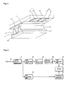
- FIG.1 is a schematic plan view showing a conventional three-electrode AC surface discharge type PDP.
- FIG. 2 is a detailed perspective view illustrating the construction of the cell shown in FIG. 1.
- the PDP includes scan electrodes Y1 to Yn and sustain electrodes Z which are formed on the bottom surface of an upper substrate 10, and address electrodes X1 to Xm formed on a lower substrate 18.
- Discharge cells 1 of the PDP are formed every crossing of the scan electrodes Y1 to Yn, the sustain electrodes Z and the address electrodes X1 to Xm.
- Each of the scan electrodes Y1 to Yn and the sustain electrodes Z includes a transparent electrode 12, and a metal bus electrode 11 that has a line width smaller than that of the transparent electrode 12 and is disposed at one edge side of the transparent electrode.
- the transparent electrode 12, which is generally made of ITO (indium tin oxide), is formed on the bottom surface of the upper substrate 10.
- the metal bus electrode, which is typically made of metal, is formed on the transparent electrode 12 and serves to reduce a voltage drop caused by the transparent electrode 12 having high resistance.
- On the bottom surface of the upper substrate 10 in which the scan electrodes Y1 to Yn and the sustain electrodes Z are disposed is laminated an upper dielectric layer 13 and a protective layer 14.
- the upper dielectric layer 13 is accumulated with wall charges generated during plasma discharging.
- the protective layer 14 is adapted to prevent damages of the electrodes Y1 to Yn, Z and the upper dielectric layer 13 due to sputtering caused during the plasma discharging, and improve efficiency of secondary electron emission.
- Magnesium oxide (MgO) is generally used as the protective layer 14.
- the address electrodes X1 to Xm are formed in the lower substrate 18 in the direction in which they intersect the scan electrodes Y1 to Yn and the sustain electrodes Z.
- a lower dielectric layer 17 and barrier ribs 15 are formed on the lower substrate 18.
- the barrier ribs 24 are formed in a stripe or grating shape to separate the discharge cells 1, thus prohibiting electrical and optical interference among neighboring discharge cells 1.
- the phosphor layer 16 is excited with ultraviolet rays generated during the plasma discharging to generate a visible light of any one of red, green and blue lights.
- An inert mixed gas such as He+Xe, Ne+Xe or He+Ne+Xe is injected into the discharge spaces of the discharge cells defined between the upper substrate 10 and the barrier ribs 15 and between the lower substrate 18 and the barrier ribs 15.
- This PDP is driven with one frame being time-divided into a plurality of sub-fields having a different number of emission in order to implement the gray scale of an image.
- Each of the sub fields is divided into a reset period for uniformly generating discharging, an address period for selecting a discharge cell, and a sustain period for implementing the gray level according to the number of discharging. For example, if it is desired to display an image with 256 gray scales, a frame period (16.67ms) corresponding to 1/60 seconds is divided into eight sub-fields SF1 to SF8. Each of the eight sub-fields SF1 to SF8 is subdivided into the reset period, the address period and the sustain period.
- FIG. 3 is a block diagram showing an apparatus for driving a PDP in the prior art.
- the conventional apparatus for driving the PDP includes a gain adjustment unit 32, an error diffusion unit 33 and a sub-field mapping unit 34 all of which are connected between an inverse gamma control unit 31 and a data alignment unit 35, and an average picture level (APL) calculation unit 36 connected between the inverse gamma control unit 31 and a waveform generator 37.
- APL average picture level
- the inverse gamma correction unit 31 linearly converts digital video data RGB of an input line 30 into the brightness for a gray scale value of a picture signal by using a 2.2 gamma table.
- the gain adjustment unit 32 compensates for color temperature by adjusting an effective gain every data of R (read), G (green) and B (blue).
- the error diffusion unit 33 finely adjusts the gray scale value by diffusing a quantization error of the digital video data RGB received from the gain adjustment unit 32 to neighboring cells.
- the sub-field mapping unit 34 maps the data received from the error diffusion unit 33 to sub-field patterns which are previously stored therein on a per bit basis, and supplies the mapped data to the data alignment unit 35.
- the data alignment unit 35 supplies the digital video data received from the sub-field mapping unit 34 to a data driving circuit of a panel 38.
- the data driving circuit is connected to address electrodes of the panel 38. It latches the data received from the data alignment unit 35 by 1 horizontal line and supplies the latched data to the address electrodes of the panel 38 in a 1 horizontal unit.
- the APL calculation unit 36 calculates an APL in one screen unit for the digital video data RGB received from the inverse gamma correction unit 31, and outputs information on the number of a sustain pulse corresponding to the calculated APL.
- the waveform generator 37 generates a timing control signal in response to the information on the number of the sustain pulse outputted from the APL calculation unit 36, and supplies the timing control signal to a scan driving circuit (not shown) and a sustain driving circuit (not shown).
- the scan driving circuit and the sustain driving circuit supplies the sustain pulse to scan electrodes and sustain electrodes of the panel 38 during a sustain period in response to the timing control signal from the waveform generator 37.
- the conventional PDP has a limit to the capability to represent the gray scale because the gray scales are represented using sub-fields included in one frame. If the gray scales are represented using only the sub-fields, however, pseudo noise is generated in the panel 38. Therefore, in the conventional PDP, in order to improve the capability to represent the gray scale, the error diffusion unit 33 is employed.
- the error diffusion unit 33 calculates quantization error data of data, differentiates the calculated error data every weight, and diffuses the differentiated error data to neighboring pixels, thus expanding the gray scale.
- error diffusion coefficients i.e., weight
- an object of the present invention is to address at least the problems and disadvantages of the background art.
- an apparatus for driving a plasma display panel including: an inverse gamma control block for performing an inverse gamma correction process on input data, typically video or image data, by using two or more gamma values, and a select unit for outputting one of two or more output data on which the inverse gamma correction operation is performed, which is outputted from the inverse gamma control block.
- a method of driving a plasma display panel including the steps of: preparing a 2.2 gamma table, and one or more modified gamma tables having a gamma value different from that of the 2.2 gamma table, performing an inverse gamma correction process on input data inputted from the outside by using the 2.2 gamma table and the one or more modified gamma tables, and outputting any one of the data on which the inverse gamma correction operation is performed using the 2.2 gamma table and the one or more modified gamma tables.
- data are subjected to inverse gamma correction in two or more inverse gamma correction units, and the inverse gamma corrected data are alternately outputted corresponding to a pixel clock, a vertical sync signal and a horizontal sync signal.
- the capability to represent the gray scale can be improved. If the capability to represent the gray scale is improved, error diffusion patterns and pseudo noise can be reduced and the picture quality can be improved.
- an apparatus for driving a plasma display panel including: an inverse gamma control block for performing an inverse gamma correction process on input data received from the outside by using two or more gamma values, and a select unit for outputting one of two or more output data on which the inverse gamma correction operation is performed, which is outputted from the inverse gamma control block.
- the inverse gamma control block may comprise two or more inverse gamma control units having at least different gamma table, for performing the inverse gamma correction process on the input data.
- One of the inverse gamma control units included in the inverse gamma control block may perform the inverse gamma correction process on the input data by using a 2.2 gamma table.
- the remaining inverse gamma control units except for the inverse gamma control unit having the 2.2 gamma table may perform the inverse gamma correction process on the input data by using a modified gamma table, which is modified from the 2.2 gamma table.
- the modified gamma table may be generated by adding a constant value to the 2.2 gamma table or subtracting a constant value from the 2.2 gamma table.
- the modified gamma table may be generated by multiplying the 2.2 gamma table by a constant value to or dividing the 2.2 gamma table by a constant value.
- the modified gamma table may be generated by shifting an output gray scale value of the 2.2 gamma table.
- the modified gamma table may be generated by changing values of some regions of the 2.2 gamma table.
- the modified gamma table may be generated by changing values of the entire region of the 2.2 gamma table.
- the select unit may output one of the two or more output data by using one or more of a pixel clock, a horizontal sync signal and a vertical sync signal.
- the select unit may alternately output the two or more output data every pixel according to the pixel clock.
- the select unit may alternately output the two or more output data every line according to the horizontal sync signal.
- the select unit may alternately output the two or more output data every frame according to the vertical sync signal.
- a method of driving a plasma display panel including the steps of: preparing a 2.2 gamma table, and one or more modified gamma tables having a gamma value different from that of the 2.2 gamma table, performing an inverse gamma correction process on input data inputted from the outside by using the 2.2 gamma table and the one or more modified gamma tables, and outputting any one of the data on which the inverse gamma correction operation is performed using the 2.2 gamma table and the one or more modified gamma tables.
- the modified gamma table may be generated by adding a constant value to the 2.2 gamma table or subtracting a constant value from the 2.2 gamma table.
- the modified gamma table may be generated by multiplying the 2.2 gamma table by a constant value to or dividing the 2.2 gamma table by a constant value.
- the modified gamma table may be generated by shifting an output gray scale value of the 2.2 gamma table.
- the modified gamma table may be generated by changing values of some regions of the 2.2 gamma table.
- the modified gamma table may be generated by changing values of the entire region of the 2.2 gamma table.
- the step of outputting any one of the inverse gamma corrected output data may include outputting one of the output data by using one or more of a pixel clock, a horizontal sync signal and a vertical sync signal which are inputted from the outside.
- the outputting any one of the inverse gamma corrected output data may include alternately outputting the output data every pixel according to the pixel clock.
- the outputting any one of the inverse gamma corrected output data may include alternately outputting the output data every line according to the horizontal sync signal.
- the outputting any one of the inverse gamma corrected output data may include alternately outputting the two or more output data every frame according to the vertical sync signal.
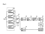
- FIG. 4 is a block diagram showing an apparatus for driving a PDP according to an embodiment of the present invention.
- the apparatus for driving the PDP includes an inverse gamma control block 52; a select unit 54; a gain adjustment unit 56, an error diffusion unit 58, a sub-field mapping unit 60 and a data alignment unit 62 all of which are connected between the select unit 54 and a panel 68; and an APL calculation unit 64 and a waveform generator 66 both of which are connected between the select unit 54 and the panel 68.
- the inverse gamma control block 52 performs an inverse gamma correction process on video data RGB received through the input line 50.
- the select unit 54 selects any one of a plurality of output values received from the inverse gamma control block 52. The construction and operation of the inverse gamma control block 52 and the select unit 54 will be described later on.
- the gain adjustment unit 56 adjusts an effective gain by the R (read), G (green) and B (blue) data on which the inverse gamma correction operation is performed, thus compensating for color temperature.
- the error diffusion unit 58 finely controls a gray scale value by diffusing a quantization error of the video data RGB received from the gain adjustment unit 56 to neighboring cells.
- the sub-field mapping unit 60 maps the data received from the error diffusion unit 58 to sub-field patterns which are previously stored therein on a per bit basis, and supplies the mapped data to the data alignment unit 62.
- the data alignment unit 62 supplies the digital video data received from the sub-field mapping unit 60 to a data driving circuit of a panel 68.
- the data driving circuit is connected to address electrodes of the panel 68. It latches the data received from the data alignment unit 62 by 1 horizontal line and supplies the latched data to the address electrodes of the panel 68 in a 1 horizontal unit.
- the APL calculation unit 64 calculates an APL in one screen unit for the data RGB on which the inverse gamma correction operation is performed, and then outputs information on the number of a sustain pulse corresponding to the calculated APL.
- the waveform generator 66 generates a timing control signal in response to the information on the number of the sustain pulse outputted from the APL calculation unit 64, and supplies the timing control signal to a scan driving circuit (not shown) and a sustain driving circuit (not shown).
- the scan driving circuit and the sustain driving circuit supplies the sustain pulse to scan electrodes and sustain electrodes of the panel 68 during a sustain period in response to the timing control signal outputted from the waveform generator 66.
- the inverse gamma control block 52 performs an inverse gamma correction on the video data RGB received from the input line 50 by using a plurality of inverse gamma tables. In other words, the inverse gamma control block 52 performs the inverse gamma correction on the video data RGB received from the input line 50 by using a plurality of gamma values, so that a plurality of output gray scale values are generated corresponding to an input gray scale value of one video data RGB.
- the inverse gamma control block 52 includes two or more inverse gamma control units, for example, four inverse gamma control units 52A, 52B, 52C and 53D, as shown in FIG. 4.
- the first inverse gamma control unit 52A carries out the inverse gamma correction process on the input data by using a 2.2 gamma value in the same manner as the prior art.
- the second inverse gamma control unit 52B performs the inverse gamma correction process on the input data by using a gamma value different from that of the first inverse gamma control unit 52A.
- the third inverse gamma control unit 52C performs the inverse gamma correction process on the input data by using a gamma value different from those of the first and second inverse gamma control units 52A, 52B.
- the fourth inverse gamma control unit 52D performs the inverse gamma correction process on the input data by using a gamma value different from those of the first to third inverse gamma control units 52A to 52C.
- an input gray scale value of one data received from the input line 50 undergoes the inverse gamma correction operation to become four gamma values, and is then outputted as four gray scale values.
- the inverse gamma control unit 52A of the plurality of the inverse gamma control units 52A to 52D that are included in the inverse gamma control block 52 has a 2.2 gamma table, and the remaining inverse gamma control units 52B to 52D have a gamma table which is modified from the 2.2 gamma table.
- the gamma tables of the second to fourth inverse gamma control units 52B to 52D can be modified into various shapes from the 2.2 gamma table.
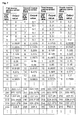
- the second to fourth inverse gamma control units 52B to 52D can generate the gamma tables by adding a constant value to the 2.2 gamma table or subtracting a constant value from the 2.2 gamma table.
- the gamma table of the second inverse gamma control unit 52B can be generated by adding a value of 0.1 to the 2.2 gamma table.
- the gamma table of the third inverse gamma control unit 52C can be generated by adding a value of 0.01 to the 2.2 gamma table.
- the gamma table of the fourth inverse gamma control unit 52D can be generated by adding a value of 0.2 to the 2.2 gamma table.
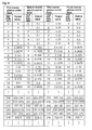
- the gamma table is generated by adding a constant value to the 2.2 gamma table, the capability of represent a low gray scale is improved, as shown in FIG. 5.
- the gray scale of '0' to '5' received from the outside outputs a gray scale value of '0'.
- a given gray scale value is outputted even in a gray scale. It is thus possible to improve the capability for representing the low gray scale.
- the gamma table of each of the second to fourth inverse gamma control units 52B to 52D can be generated by shifting the 2.2 gamma table up and down, as shown in FIG. 6.
- the gamma table of the second inverse gamma control unit 52B is generated by upwardly shifting the 2.2 gamma table every 3 gray levels.
- the gamma table of the third inverse gamma control unit 52C is generated by upwardly shifting the 2.2 gamma table every 6 gray levels.
- the gamma table of the fourth inverse gamma control unit 52D is generated by upwardly shifting the 2.2 gamma table every 4 gray levels. In this time, if the gamma table is generated by shifting the 2.2 gamma table, the capability to represent the gray scale can be improved, as shown in FIG. 6.
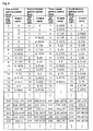
- the gamma table of each of the second to fourth inverse gamma control units 52B to 52D can be generated by modifying some gray scales of the 2.2 gamma table, as shown in FIG. 7.
- the gamma table of each of the second to fourth inverse gamma control units 52B to 52D can be generated by modifying a low gray scale region (for example, below 16 gray scales) of the 2.2 gamma table.
- the gamma tables of the second to fourth inverse gamma control units 52B to 52D can be generated by a variety of methods.
- the gamma tables of the second to fourth inverse gamma control units 52B to 52D can be generated by multiplying the 2.2 gamma table by a constant value to or dividing the 2.2 gamma table by a constant value.
- the gamma tables of the second to fourth inverse gamma control units 52B to 52D can be generated by mixing the methods shown in FIG. 5 and FIG. 7.
- an inverse gamma table of the second inverse gamma control unit 52B can be generated by adding a constant value to the 2.2 gamma table or subtracting a constant value from the 2.2 gamma table.
- An inverse gamma table of the third inverse gamma control unit 52C can be generated by changing some regions of the 2.2 gamma table.
- an inverse gamma table of the fourth inverse gamma control unit 52D can be generated by shifting the 2.2 gamma table.
- the gamma tables of the second to fourth inverse gamma control units 52B to 52D are determined to have a value in which an optimum image is displayed experimentally.
- the select unit 54 outputs any one of the gray scale values which are received from the first to fourth inverse gamma control units 52A to 52D. To this end, the select unit 54 receives a pixel clock P, a horizontal sync signal H and a vertical sync signal V from the outside. The select unit 54 that received the pixel clock P, the horizontal sync signal H and the vertical sync signal V selects any one of the gray scale values received from the first to fourth inverse gamma control units 52A to 52D by using one of the pixel clock P, the horizontal sync signal H and the vertical sync signal V.
- the select unit 54 alternately displays first output gray scales A of the first inverse gamma control unit 52A and second output gray scales B of the second inverse gamma control unit 52B corresponding to the pixel clock P and the horizontal sync signal H in an i th (i is natural number) frame, as shown in FIG. 8a.
- two of the four output gray scale values are alternately displayed corresponding to the pixel clock P and the horizontal sync signal H.
- the select unit 54 then alternately displays third output gray scales C of the third inverse gamma control unit 52C and fourth output gray scales D of the fourth inverse gamma control unit 52D corresponding to the pixel clock P and the horizontal sync signal H, in an (i+1) th frame separated by the vertical sync signal V.
- the gray scale can be expanded on average.
- the gray scales that can be represented are limited.
- an image is displayed using data on which an inverse gamma correction operation is performed by using two or more different gamma tables. Therefore, a variety of gray scales can be displayed on average.
- Error diffusion is performed by using output gray scale values (i.e., output data) outputted from the select unit 54.
- An error diffusion pattern is prevented from occurring. That is, the error diffusion pattern is generated since the error diffusion coefficients are repeated constantly.
- data on which an inverse gamma correction operation is performed by using different gamma tables is outputted from the select unit 54 every pixel, line and frame. There occurs a difference in a gray scale value every pixel. Accordingly, although error diffusion is performed by using error diffusion coefficients having a constant weight, the error diffusion pattern is not generated.
- the outputs of the select unit 54 can be set variously corresponding to one or more of the pixel clock P, the horizontal sync signal H and the vertical sync signal V.
- the select unit 54 alternately outputs the first to fourth output gray scales A to D corresponding to the pixel clock P, and also alternately outputs the first to fourth output gray scales A to D every line corresponding to the horizontal sync signal H, as shown in FIG. 8b.
- the select unit 54 alternately outputs the first to fourth output gray scales A to D every frame corresponding to the vertical sync signal V.
- the output in the select unit 54 is experimentally decided to have a value in which an optimum image can be displayed.
Landscapes
- Engineering & Computer Science (AREA)
- Physics & Mathematics (AREA)
- Computer Hardware Design (AREA)
- General Physics & Mathematics (AREA)
- Theoretical Computer Science (AREA)
- Plasma & Fusion (AREA)
- Power Engineering (AREA)
- Control Of Indicators Other Than Cathode Ray Tubes (AREA)
- Transforming Electric Information Into Light Information (AREA)
- Control Of Gas Discharge Display Tubes (AREA)
Applications Claiming Priority (2)
| Application Number | Priority Date | Filing Date | Title |
|---|---|---|---|
| KR2003086380 | 2003-12-01 | ||
| KR10-2003-0086380A KR100533727B1 (ko) | 2003-12-01 | 2003-12-01 | 플라즈마 디스플레이 패널의 구동 장치 |
Publications (2)
| Publication Number | Publication Date |
|---|---|
| EP1538592A2 true EP1538592A2 (de) | 2005-06-08 |
| EP1538592A3 EP1538592A3 (de) | 2006-09-20 |
Family
ID=34464788
Family Applications (1)
| Application Number | Title | Priority Date | Filing Date |
|---|---|---|---|
| EP04257465A Withdrawn EP1538592A3 (de) | 2003-12-01 | 2004-12-01 | Gerät und Verfahren zur Ansteuerung einer Plasmaanzeigetafel |
Country Status (6)
| Country | Link |
|---|---|
| US (1) | US7414598B2 (de) |
| EP (1) | EP1538592A3 (de) |
| JP (1) | JP4925576B2 (de) |
| KR (1) | KR100533727B1 (de) |
| CN (1) | CN100421138C (de) |
| TW (1) | TWI298863B (de) |
Cited By (2)
| Publication number | Priority date | Publication date | Assignee | Title |
|---|---|---|---|---|
| US7414598B2 (en) | 2003-12-01 | 2008-08-19 | Lg Electronics Inc. | Apparatus and method for driving plasma display panel |
| WO2011097059A2 (en) | 2010-02-02 | 2011-08-11 | Microsoft Corporation | Enhancement of images for display on liquid crystal displays |
Families Citing this family (13)
| Publication number | Priority date | Publication date | Assignee | Title |
|---|---|---|---|---|
| US8305301B1 (en) | 2003-02-04 | 2012-11-06 | Imaging Systems Technology | Gamma correction |
| US8289233B1 (en) | 2003-02-04 | 2012-10-16 | Imaging Systems Technology | Error diffusion |
| US7595773B2 (en) * | 2005-05-18 | 2009-09-29 | Chunghwa Picture Tubes, Ltd. | Brightness correction method for plasma display and device thereof |
| CN100372362C (zh) * | 2005-10-14 | 2008-02-27 | 四川世纪双虹显示器件有限公司 | 一种重建等离子显示器暗区灰度级的实时图像处理器 |
| JP4198720B2 (ja) * | 2006-05-17 | 2008-12-17 | Necエレクトロニクス株式会社 | 表示装置、表示パネルドライバ、及び表示パネルの駆動方法 |
| TWI342532B (en) * | 2006-07-10 | 2011-05-21 | Himax Tech Inc | Method for generating a gamma table |
| KR100815755B1 (ko) * | 2006-11-09 | 2008-03-20 | 삼성에스디아이 주식회사 | 감마 보정 장치 및 이를 구비한 유기 전계발광 표시장치 |
| US8248328B1 (en) | 2007-05-10 | 2012-08-21 | Imaging Systems Technology | Plasma-shell PDP with artifact reduction |
| KR100970883B1 (ko) * | 2008-10-08 | 2010-07-20 | 한국과학기술원 | 영역 특성을 고려한 영상 보정 장치 및 그 방법 |
| KR20150081174A (ko) * | 2014-01-03 | 2015-07-13 | 삼성디스플레이 주식회사 | 액정표시장치 및 이의 구동방법 |
| CN107331338B (zh) | 2017-08-28 | 2021-08-17 | 京东方科技集团股份有限公司 | 一种阵列基板、显示装置及其检测方法 |
| WO2019123632A1 (ja) * | 2017-12-22 | 2019-06-27 | Necディスプレイソリューションズ株式会社 | 映像処理装置、映像表示装置及び映像処理方法 |
| KR20250010433A (ko) * | 2023-07-12 | 2025-01-21 | 삼성전자주식회사 | 표시 장치 및 이미지 표시 방법 |
Family Cites Families (11)
| Publication number | Priority date | Publication date | Assignee | Title |
|---|---|---|---|---|
| JP3440814B2 (ja) * | 1998-03-20 | 2003-08-25 | 日本電気株式会社 | 映像信号処理装置 |
| JP4016493B2 (ja) * | 1998-08-05 | 2007-12-05 | 三菱電機株式会社 | ディスプレイ装置及びその多階調化回路 |
| AU739565B2 (en) * | 1998-10-06 | 2001-10-18 | Matsushita Electric Industrial Co., Ltd. | Gamma correction circuit and gamma correction method |
| WO2000043979A1 (en) * | 1999-01-22 | 2000-07-27 | Matsushita Electric Industrial Co., Ltd. | Apparatus and method for making a gray scale display with subframes |
| CN1160681C (zh) * | 1999-04-12 | 2004-08-04 | 松下电器产业株式会社 | 图象显示装置 |
| US6965389B1 (en) | 1999-09-08 | 2005-11-15 | Victor Company Of Japan, Ltd. | Image displaying with multi-gradation processing |
| JP2001075521A (ja) * | 1999-09-08 | 2001-03-23 | Victor Co Of Japan Ltd | 表示装置の誤差拡散処理方法 |
| JP2001092407A (ja) * | 1999-09-24 | 2001-04-06 | Victor Co Of Japan Ltd | 画像表示装置 |
| TW508560B (en) | 2001-04-03 | 2002-11-01 | Chunghwa Picture Tubes Ltd | Method for performing different anti-compensation processes by segments on image gray levels inputted to plasma flat display |
| TW582006B (en) * | 2002-06-14 | 2004-04-01 | Chunghwa Picture Tubes Ltd | Brightness correction apparatus and method for plasma display |
| KR100533727B1 (ko) * | 2003-12-01 | 2005-12-06 | 엘지전자 주식회사 | 플라즈마 디스플레이 패널의 구동 장치 |
-
2003
- 2003-12-01 KR KR10-2003-0086380A patent/KR100533727B1/ko not_active Expired - Fee Related
-
2004
- 2004-11-30 JP JP2004347490A patent/JP4925576B2/ja not_active Expired - Fee Related
- 2004-12-01 TW TW093137039A patent/TWI298863B/zh not_active IP Right Cessation
- 2004-12-01 US US11/000,519 patent/US7414598B2/en not_active Expired - Fee Related
- 2004-12-01 CN CNB2004100982853A patent/CN100421138C/zh not_active Expired - Fee Related
- 2004-12-01 EP EP04257465A patent/EP1538592A3/de not_active Withdrawn
Cited By (7)
| Publication number | Priority date | Publication date | Assignee | Title |
|---|---|---|---|---|
| US7414598B2 (en) | 2003-12-01 | 2008-08-19 | Lg Electronics Inc. | Apparatus and method for driving plasma display panel |
| CN100421138C (zh) * | 2003-12-01 | 2008-09-24 | Lg电子株式会社 | 驱动等离子显示面板的装置和方法 |
| WO2011097059A2 (en) | 2010-02-02 | 2011-08-11 | Microsoft Corporation | Enhancement of images for display on liquid crystal displays |
| CN102726036A (zh) * | 2010-02-02 | 2012-10-10 | 微软公司 | 用于在液晶显示器上显示的图像的增强 |
| EP2532152A4 (de) * | 2010-02-02 | 2013-08-14 | Microsoft Corp | Erweiterung von bildern zur anzeige auf flüssigkristallanzeigen |
| US8866837B2 (en) | 2010-02-02 | 2014-10-21 | Microsoft Corporation | Enhancement of images for display on liquid crystal displays |
| CN102726036B (zh) * | 2010-02-02 | 2015-06-24 | 微软公司 | 用于在液晶显示器上显示的图像的增强 |
Also Published As
| Publication number | Publication date |
|---|---|
| JP2005165327A (ja) | 2005-06-23 |
| CN1624745A (zh) | 2005-06-08 |
| KR20050052815A (ko) | 2005-06-07 |
| TW200523851A (en) | 2005-07-16 |
| TWI298863B (en) | 2008-07-11 |
| CN100421138C (zh) | 2008-09-24 |
| JP4925576B2 (ja) | 2012-04-25 |
| US7414598B2 (en) | 2008-08-19 |
| US20050162352A1 (en) | 2005-07-28 |
| KR100533727B1 (ko) | 2005-12-06 |
| EP1538592A3 (de) | 2006-09-20 |
Similar Documents
| Publication | Publication Date | Title |
|---|---|---|
| EP1536400B1 (de) | Verfahren zur Verarbeitung eines Grautons in einer Plamaanzeigetafel und dieses benutzendes Gerät | |
| EP1531451A2 (de) | Verfahren und Gerät zur Steuerung der Initialisierung in einer Plasmaanzeigetafel | |
| US7414598B2 (en) | Apparatus and method for driving plasma display panel | |
| US20050127846A1 (en) | Apparatus and method for driving plasma display panel | |
| US7256794B2 (en) | Method and apparatus for processing video data of display device | |
| US7408530B2 (en) | Apparatus and method of driving a plasma display panel | |
| JP2005092221A (ja) | プラズマディスプレイパネルの駆動装置及び方法 | |
| US20020175922A1 (en) | Method and apparatus for eliminating flicker in plasma display panel | |
| EP1526499B1 (de) | Verfahren und Vorrichtung zur Ansteuerung einer Plasmaanzeigetafel | |
| US20050134615A1 (en) | Method and apparatus for driving plasma display panel | |
| JP4160575B2 (ja) | プラズマディスプレイ装置及びその駆動方法 | |
| US20070024609A1 (en) | Apparatus and method of driving plasma display panel | |
| KR100733881B1 (ko) | 플라즈마 디스플레이 패널의 구동장치 및 구동방법 | |
| US7486260B2 (en) | Plasma display panel having a driving apparatus and method for displaying pictures | |
| KR100514259B1 (ko) | 플라즈마 디스플레이 패널의 구동 장치 및 방법 | |
| US7164396B2 (en) | Method and apparatus of driving plasma display panel | |
| WO2005057540A1 (en) | Method and apparatus of processing video data for plasma display panel | |
| KR100514260B1 (ko) | 플라즈마 디스플레이 패널의 구동장치 | |
| KR100719033B1 (ko) | 플라즈마 디스플레이 패널의 구동장치 및 구동 방법 | |
| KR20050111007A (ko) | 플라즈마 디스플레이 패널의 구동방법 및 장치 | |
| KR20070027664A (ko) | 플라즈마 디스플레이 패널의 구동장치 및 구동 방법 | |
| KR20030090812A (ko) | 플라즈마 디스플레이 패널 및 그의 구동방법 | |
| KR20050012466A (ko) | 플라즈마 디스플레이 패널의 구동장치 및 구동방법 | |
| KR20040085740A (ko) | 플라즈마 디스플레이 패널의 오차확산방법 및 장치 |
Legal Events
| Date | Code | Title | Description |
|---|---|---|---|
| PUAI | Public reference made under article 153(3) epc to a published international application that has entered the european phase |
Free format text: ORIGINAL CODE: 0009012 |
|
| AK | Designated contracting states |
Kind code of ref document: A2 Designated state(s): AT BE BG CH CY CZ DE DK EE ES FI FR GB GR HU IE IS IT LI LT LU MC NL PL PT RO SE SI SK TR |
|
| AX | Request for extension of the european patent |
Extension state: AL BA HR LV MK YU |
|
| PUAL | Search report despatched |
Free format text: ORIGINAL CODE: 0009013 |
|
| AK | Designated contracting states |
Kind code of ref document: A3 Designated state(s): AT BE BG CH CY CZ DE DK EE ES FI FR GB GR HU IE IS IT LI LT LU MC NL PL PT RO SE SI SK TR |
|
| AX | Request for extension of the european patent |
Extension state: AL BA HR LV MK YU |
|
| 17P | Request for examination filed |
Effective date: 20060905 |
|
| 17Q | First examination report despatched |
Effective date: 20070216 |
|
| AKX | Designation fees paid |
Designated state(s): DE FR GB NL |
|
| STAA | Information on the status of an ep patent application or granted ep patent |
Free format text: STATUS: THE APPLICATION IS DEEMED TO BE WITHDRAWN |
|
| 18D | Application deemed to be withdrawn |
Effective date: 20130702 |