EP1538339B1 - Radialpumpe - Google Patents
Radialpumpe Download PDFInfo
- Publication number
- EP1538339B1 EP1538339B1 EP20040450193 EP04450193A EP1538339B1 EP 1538339 B1 EP1538339 B1 EP 1538339B1 EP 20040450193 EP20040450193 EP 20040450193 EP 04450193 A EP04450193 A EP 04450193A EP 1538339 B1 EP1538339 B1 EP 1538339B1
- Authority
- EP
- European Patent Office
- Prior art keywords
- radial
- flow pump
- covering ring
- housing
- impeller
- Prior art date
- Legal status (The legal status is an assumption and is not a legal conclusion. Google has not performed a legal analysis and makes no representation as to the accuracy of the status listed.)
- Expired - Lifetime
Links
- 238000002485 combustion reaction Methods 0.000 description 5
- 239000000498 cooling water Substances 0.000 description 3
- 230000006835 compression Effects 0.000 description 2
- 238000007906 compression Methods 0.000 description 2
- 239000002826 coolant Substances 0.000 description 2
- 238000006073 displacement reaction Methods 0.000 description 2
- XLYOFNOQVPJJNP-UHFFFAOYSA-N water Substances O XLYOFNOQVPJJNP-UHFFFAOYSA-N 0.000 description 2
- 230000002411 adverse Effects 0.000 description 1
- 230000015572 biosynthetic process Effects 0.000 description 1
- 125000004122 cyclic group Chemical group 0.000 description 1
- 230000001627 detrimental effect Effects 0.000 description 1
- 239000000446 fuel Substances 0.000 description 1
- 238000005086 pumping Methods 0.000 description 1
Images

Classifications
-
- F—MECHANICAL ENGINEERING; LIGHTING; HEATING; WEAPONS; BLASTING
- F04—POSITIVE - DISPLACEMENT MACHINES FOR LIQUIDS; PUMPS FOR LIQUIDS OR ELASTIC FLUIDS
- F04D—NON-POSITIVE-DISPLACEMENT PUMPS
- F04D29/00—Details, component parts, or accessories
- F04D29/08—Sealings
- F04D29/16—Sealings between pressure and suction sides
- F04D29/165—Sealings between pressure and suction sides especially adapted for liquid pumps
- F04D29/167—Sealings between pressure and suction sides especially adapted for liquid pumps of a centrifugal flow wheel
-
- F—MECHANICAL ENGINEERING; LIGHTING; HEATING; WEAPONS; BLASTING
- F04—POSITIVE - DISPLACEMENT MACHINES FOR LIQUIDS; PUMPS FOR LIQUIDS OR ELASTIC FLUIDS
- F04D—NON-POSITIVE-DISPLACEMENT PUMPS
- F04D15/00—Control, e.g. regulation, of pumps, pumping installations or systems
- F04D15/0027—Varying behaviour or the very pump
- F04D15/0033—By-passing by increasing clearance between impeller and its casing
Definitions
- the invention relates to a radial pump with a housing in which a driven by a shaft impeller is rotatably mounted with a on the suction side of the impeller in the housing axially in the direction of the impeller between two end positions slidably mounted cover ring, wherein by moving the cover ring from a through a housing stop limited first end position between a wheel and housing formed gap is releasable, wherein the cover ring is automatically adjustable depending on the pressure difference between the pressure and suction side of the impeller, wherein the cover ring in at least one defined position, preferably at least in the first end position, by a positioning element preferably formed by at least one latching device can be positioned.
- cooling water pumps of internal combustion engines are designed so that even at relatively low engine speeds high coolant flows can be provided.
- the delivered volume flow, but also the power consumption of the pump is much higher than necessary, which adversely affects fuel consumption. Apart from that, it can come in the high speed range to cavitation phenomena.
- a cooling water pump for an internal combustion engine is known.
- a displaceable in the axial direction cover ring is inserted.
- the cover ring is adjustable by an actuator having a pressure cell depending on parameters of the internal combustion engine. Due to the displacement of the cover ring, the width of a gap between the ring and the impeller of the water pump is variable, so that the cooling water flow rate is variable. This makes it possible to shorten the warm-up phase of the internal combustion engine and to reduce the amount of harmful exhaust gas components.
- US Pat. No. 2,786,420 A also describes a radial pump in which a cover ring can be adjusted by means of a pressure cell as a function of the pressure difference between the pressure and suction side.
- FR 2 681 906 A1 describes a radial pump for coolant for internal combustion engines, wherein a housing wall adjoining the main pumping chamber of the pump can be displaced so that an impeller gap between the housing wall and the impeller and thus the delivery flow of the pump can be adapted to one or more engine parameters.
- the object of the invention is to reduce as much as possible the flow rate and the power consumption at high speeds while ensuring a stable operation.
- the positioning element has at least one approximately radially with respect to the impeller axis spring-loaded pressure body, which cooperates in the defined position with a reciprocally shaped locking element and is slidably disposed along a guide surface and that the pressure body is formed by a spring ring.
- the latching element is preferably formed by a recess in the guide surface.
- the guide surface is formed by a suction-side inner surface of the housing and the pressure body is arranged in the jacket region of the cover ring.
- the guide surface is formed by the jacket region of the cover ring and that the pressure body is arranged in the region of an inner surface of the housing on the suction chamber side.
- the guide surface is inclined with respect to the wheel axis by an angle less than about 20 °, preferably less than about 10 °.
- a pressure spring acting on the pressure body can be arranged in a radial bore of the cover ring or of the housing.
- the pressure body has a convex surface.
- At least one short-circuit channel is arranged in the region of the cover ring.
- the short-circuit channel can be formed by at least one formation in the housing and / or in the cover ring.
- the short-circuit channel is opened by the cover ring and is designed so that the flow cross-section increases with the deflection of the cover ring. This ensures that in the upper speed range relatively large flow rates are diverted, causing the Power consumption of the radial pump can be significantly reduced in this operating range.
- the gap between the impeller and housing is independently adapted to the current impeller speed, thereby consuming actuators can be omitted.
- the cover ring formed at least by a restoring element restoring force in the direction of the first end position.
- the restoring element is formed by a resilient biasing means, preferably a return spring, which acts in the direction of the impeller axis on the cover ring.
- the radial pump 1 has a housing 2, in which a shaft 3 for driving an impeller 4 by means of a bearing 5 is rotatably mounted.
- the suction side of the radial pump 1 is denoted by reference numeral 6, the pressure side by reference numeral 7.
- the impeller 4 around the housing 2 forms a spiral channel 8.
- a cover ring 9 is slidably disposed in the housing 2 in the direction of the impeller axis 10 between a first and a second end position. In the first end position shown in FIG. 1, a gap 11 formed between impeller 4 and housing 2 is covered by cover ring 9, so that leakage flows between pressure side 7 and suction side 6 are prevented.
- the cover ring 9 is moved by at least one return element 12 in the first end position or held in this.
- the return element 12 shown in FIG. 2 consists of a restoring spring 14 formed by a spring plate, which acts in the axial direction on the cover ring 9.
- the positioning element 13 shown in Fig. 3 is disposed in the jacket portion 15 of the cover ring 9 and has a spring-loaded by a compression spring 16 pressure body 17, wherein the compression spring 16 is disposed in a radial bore 18 in the jacket portion 15 of the cover ring 9.
- the pressure body 17 may be formed, for example, by a ball or hemisphere 17a.
- the pressure body 17 rests on a guide surface 19 formed by a suction-side inner surface 2a of the housing 2 and slides along the axial deflection of the cover ring along this, wherein the pressure body 17 engages in the first end position in a formed by a recess 20 form element and thus the position stabilized the cover ring 9.
- the guide surface 19 is slightly inclined relative to the impeller axis 10, wherein the angle ⁇ between the guide surface 19 and the impeller axis 10 is less than about 10 °.
- the cover ring 9 rests against a stop 21 formed by the housing 2.
- the cover ring 9 is moved in response to the pressure difference between the pressure p 2 of the pressure side 7 and the pressure p 1 of the suction side 6 from the first end position determining a rest position in the second end position.
- the cover ring 9 Up to a predefined speed of the impeller 4, which is associated with a certain flow, the cover ring 9 is positioned in the first end position shown in Fig. 1 with a very small gap 11 with respect to the impeller 4, so that an optimum efficiency is achieved.
- This position is defined on the one hand by the stop 21 in the housing, on the other hand by the return element 12 and the positioning element 13.
- the return element 12 and the positioning element 13 can also be used in combination in order to ensure a demand-oriented control characteristic.
- the reset and positioning elements 12, 13 are designed so that at a certain pressure difference p 2 - p 1, an axial displacement of the cover ring 9 takes place away from the impeller 4. Depending on the design of the reset and positioning elements 12, 13, this axial adjustment can take place continuously or abruptly above a certain speed.
- the increasing axial gap 11 between the impeller 4 and cover ring 9 causes a reduction in the flow rate and thereby also a reduction in power consumption at high speeds. Furthermore, the cavitation occurring in the high speed range is prevented.
- the housing 2 has at least one short-circuit channel 23, which enables the flow connection according to the arrow S between the pressure side 7 and suction side 6 of the radial pump 1 in the deflection of the cover ring 9 shown in FIG.
- the short-circuit channel 23 is opened by an edge 24 of the cover ring 9 and is designed so that the flow cross-section increases with the size of the deflection of the cover ring 9. As a result, relatively large quantities of the pumped medium are deactivated at high speeds.
Landscapes
- Engineering & Computer Science (AREA)
- Mechanical Engineering (AREA)
- General Engineering & Computer Science (AREA)
- Structures Of Non-Positive Displacement Pumps (AREA)
Description
- Die Erfindung betrifft eine Radialpumpe mit einem Gehäuse, in welchem ein durch eine Welle angetriebenes Laufrad drehbar gelagert ist, mit einem auf der Saugseite des Laufrades im Gehäuse axial in Richtung der Laufradachse zwischen zwei Endlagen verschiebbar gelagerten Deckring, wobei durch Verschieben des Deckringes aus einer durch einen Gehäuseanschlag begrenzten ersten Endlage ein zwischen Laufrad und Gehäuse ausgebildeter Spalt freigebbar ist, wobei der Deckring selbsttätig in Abhängigkeit der Druckdifferenz zwischen Druck- und Saugseite des Laufrades verstellbar ist, wobei der Deckring in zumindest einer definierten Lage, vorzugsweise zumindest in der ersten Endlage, durch ein vorzugsweise durch zumindest eine Rasteinrichtung gebildetes Positionierelement positionierbar ist.
- Insbesondere Kühlwasserpumpen von Brennkraftmaschinen sind so konzipiert, dass bereits bei relativ niedrigen Motordrehzahlen hohe Kühlmitteldurchflüsse bereitgestellt werden können. Bei hohen Motordrehzahlen ist der geförderte Volumenstrom, aber auch die Leistungsaufnahme der Pumpe viel höher als erforderlich, was sich nachteilig auf den Kraftstoffverbrauch auswirkt. Abgesehen davon, kann es im hohen Drehzahlbereich zu Kavitationserscheinungen kommen.
- Aus der DE 41 42 120 A1 ist eine Kühlwasserpumpe für eine Brennkraftmaschine bekannt. In eine zwischen einem wasserführenden Kanal und einem Wasserpumpengehäuse angeordnete Öffnung ist ein in axialer Richtung verschiebbarer Deckring eingesetzt. Der Deckring ist durch ein eine Druckdose aufweisendes Stellglied in Abhängigkeit von Parametern der Brennkraftmaschine verstellbar. Durch die Verschiebung des Deckringes ist die Breite eines Spaltes zwischen dem Ring und dem Laufrad der Wasserpumpe variabel, so dass der Kühlwasserdurchsatz veränderbar ist. Dies ermöglicht es, die Warmlaufphase der Brennkraftmaschine zu verkürzen und die Menge der schädlichen Abgasbestandteile zu verringern.
- Auch die US 2,786,420 A beschreibt eine Radialpumpe, bei der mittels einer Druckdose ein Deckring in Abhängigkeit der Druckdifferenz zwischen Druck- und Saugseite verstellt werden kann.
- Die FR 2 681 906 A1 beschreibt eine Radialpumpe für Kühlmittel für Brennkraftmaschinen, wobei eine an die Hauptpumpkammer der Pumpe grenzende Gehäusewand so verschoben werden kann, dass ein Laufradspalt zwischen Gehäusewand und Laufrad und damit der Förderstrom der Pumpe an einen oder mehrere Motorparameter angepasst werden kann.
- Durch Druckfluktuationen kann es aber in bestimmten Drehzahlbereichen zu zylindrischen Verstellbewegungen des Deckringes kommen, was sich nachteilig auf den stabilen Betrieb auswirkt.
- Aufgabe der Erfindung ist es, auf möglichst einfache Weise die Durchflussmenge und die Leistungsaufnahme bei hohen Drehzahlen zu vermindern und dabei einen stabilen Betrieb zu gewährleisten.
- Erfindungsgemäß wird dies dadurch erreicht, dass das Positionierelement zumindest einen etwa radial bezüglich der Laufradachse federbelasteten Druckkörper aufweist, welcher in der definierten Lage mit einem reziprok geformten Rastelement zusammenwirkt und entlang einer Führungsfläche gleitbar angeordnet ist und dass der Druckkörper durch einen Federring gebildet ist. Dadurch können Flattererscheinungen des Deckringes in bestimmten Drehzahlbereichen, welche ein zyklisches Öffnen und Schließen des Spaltes zwischen Gehäuse und Laufrad bewirken würden, verhindert werden. Vorteilhafter Weise ist dabei vorgesehen sein, dass das Rastelement vorzugsweise durch eine Einbuchtung in der Führungsfläche gebildet ist.
- In einer besonders vorteilhaften Ausführungsvariante ist vorgesehen, dass die Führungsfläche durch eine saugseitige Innenfläche des Gehäuses gebildet ist und der Druckkörper im Mantelbereich des Deckringes angeordnet ist. Gemäß einer dazu reziproken Ausführungsvariante ist vorgesehen, dass die Führungsfläche durch den Mantelbereich des Deckringes gebildet ist und dass der Druckkörper im Bereich einer saugraumseitigen Innenfläche des Gehäuses angeordnet ist.
- Um die Rückstellbewegung des Deckringes zu unterstützen, ist es vorteilhaft, wenn die Führungsfläche bezüglich der Laufradachse um einen Winkel kleiner als etwa 20°, vorzugsweise kleiner als etwa 10° geneigt ist.
- Eine auf den Druckkörper einwirkende Druckfeder kann in einer radialen Bohrung des Deckringes oder des Gehäuses angeordnet sein.
- Gemäß einer einfachen Ausführungsvariante der Erfindung ist vorgesehen, dass der Druckkörper eine konvexe Oberfläche aufweist.
- In einer besonders bevorzugten Ausführungsvariante der Erfindung ist vorgesehen, dass im Bereich des Deckringes zumindest ein Kurzschlusskanal angeordnet ist. Der Kurzschlusskanal kann durch zumindest eine Ausformung im Gehäuse und/oder im Deckring gebildet sein. Der Kurzschlusskanal wird dabei durch den Deckring aufgesteuert und ist so gestaltet, dass der Durchflussquerschnitt mit der Auslenkung des Deckringes zunimmt. Dadurch wird erreicht, dass im oberen Drehzahlbereich relativ große Fördermengen abgesteuert werden, wodurch die Leistungsaufnahme der Radialpumpe in diesem Betriebsbereich wesentlich vermindert werden kann.
- Durch den durch die Druckdifferenz zwischen Druck- und Saugseite verschiebbaren Deckring wird der Spalt zwischen Laufrad und Gehäuse selbständig der aktuellen Laufraddrehzahl angepasst, wodurch aufwendige Stellglieder entfallen können.
- Gemäß der Erfindung ist weiters vorgesehen, dass auf den Deckring eine zumindest durch ein Rückstellelement gebildete Rückstellkraft in Richtung der ersten Endlage einwirkt. Vorzugsweise ist dabei vorgesehen, dass das Rückstellelement durch eine elastische Vorspanneinrichtung, vorzugsweise eine Rückstellfeder, gebildet ist, welche in Richtung der Laufradachse auf den Deckring einwirkt.
- Die Erfindung wird im Folgenden anhand der Figuren näher erläutert. Es zeigen
- Fig. 1
- eine erfindungsgemäße Radialpumpe in einem Längsschnitt in einer ersten Ausführungsvariante,
- Fig. 2
- das Detail II aus Fig. 1,
- Fig. 3
- das Detail III aus Fig. 1,
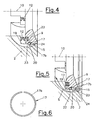
- Fig. 4
- eine erfindungsgemäße Radialpumpe gemäß dem Detail aus Fig. 3 in einer zweiten Ausführungsvariante in einer Ruhstellung des Deckringes,
- Fig. 5
- ein Detail gemäß Fig. 4 in einer Auslenkstellung des Deckringes, und
- Fig. 6
- ein Positionselement in einer Ausführungsvariante.
- In den Figuren sind funktionsgleiche Teile mit gleichen Bezugszeichen versehen.
- Die Radialpumpe 1 weist ein Gehäuse 2 auf, in welchem eine Welle 3 zum Antrieb eines Laufrades 4 mittels eines Lagers 5 drehbar gelagert ist. Die Saugseite der Radialpumpe 1 ist mit Bezugszeichen 6, die Druckseite mit Bezugszeichen 7 bezeichnet. Um das Laufrad 4 herum bildet das Gehäuse 2 einen Spiralkanal 8 aus. Auf der Saugseite 6 des Laufrades 4 ist im Gehäuse 2 ein Deckring 9 in Richtung der Laufradachse 10 zwischen einer ersten und einer zweiten Endlage verschiebbar angeordnet. In der in Fig. 1 dargestellten ersten Endlage wird ein zwischen Laufrad 4 und Gehäuse 2 ausgebildeter Spalt 11 durch den Deckring 9 verdeckt, so dass Leckageströme zwischen Druckseite 7 und Saugseite 6 unterbunden werden.
- Der Deckring 9 wird durch zumindest ein Rückstellelement 12 in die erste Endlage bewegt bzw. in dieser festgehalten. Das in Fig. 2 dargestellte Rückstellelement 12 besteht aus einer durch ein Federblech gebildeten Rückstellfeder 14, welche in axialer Richtung auf den Deckring 9 einwirkt.
- Durch ein Positionierelement 13 wird der Deckring 9 in einer vordefinierten Lage, etwa der ersten Endlage, gehalten. Dadurch wird ein Flattern des Deckringes 9 bei kritischen Drehzahlen verhindert. Das in Fig. 3 dargestellte Positionierelement 13 ist im Mantelbereich 15 des Deckringes 9 angeordnet und weist einen durch eine Druckfeder 16 federbelasteten Druckkörper 17 auf, wobei die Druckfeder 16 in einer radialen Bohrung 18 im Mantelbereich 15 des Deckringes 9 angeordnet ist. Der Druckkörper 17 kann beispielsweise durch eine Kugel oder Halbkugel 17a gebildet sein. Der Druckkörper 17 liegt auf einer durch eine saugseitige Innenfläche 2a des Gehäuses 2 gebildeten Führungsfläche 19 auf und gleitet bei axialer Auslenkung des Deckringes an dieser entlang, wobei der Druckkörper 17 in der ersten Endlage in ein durch eine Einbuchtung 20 gebildetes Formelement einrastet und somit die Position des Deckringes 9 stabilisiert. Um die Rückstellbewegung des Deckringes 9 in Richtung der ersten Endlage zu unterstützen, ist die Führungsfläche 19 bezüglich der Laufradachse 10 leicht geneigt ausgebildet, wobei der Winkel α zwischen der Führungsfläche 19 und der Laufradachse 10 kleiner als etwa 10° ist. In der ersten Endlage liegt der Deckring 9 an einem durch das Gehäuse 2 gebildeten Anschlag 21 an.
- Der Deckring 9 wird in Abhängigkeit der Druckdifferenz zwischen dem Druck p2 der Druckseite 7 und dem Druck p1 der Saugseite 6 aus der eine Ruhelage bestimmenden ersten Endlage in die zweite Endlage bewegt. Bis zu einer vordefinierten Drehzahl des Laufrades 4, welcher eine bestimmte Durchflussmenge zugeordnet ist, ist der Deckring 9 in der in Fig. 1 dargestellten ersten Endlage mit sehr geringem Spalt 11 bezüglich dem Laufrad 4 positioniert, so dass ein optimaler Wirkungsgrad erreicht wird. Diese Position wird einerseits durch den Anschlag 21 im Gehäuse, andererseits durch das Rückstellelement 12 und das Positionierelement 13 definiert. Je nach Auslegung können Rückstellelement 12 und Positionierelement 13 auch kombiniert angewendet werden, um eine bedarfsgerechte Regelcharakteristik zu gewährleisten.
- Die Rückstell- und Positionierelemente 12, 13 sind so ausgelegt, dass bei einer bestimmten Druckdifferenz p2 - p1 eine axiale Verschiebung des Deckringes 9 vom Laufrad 4 weg stattfindet. Je nach Auslegung der Rückstell- und Positionierelemente 12, 13 kann diese axiale Verstellung kontinuierlich oder ab einer bestimmten Drehzahl abrupt erfolgen.
- Der sich vergrößernde axiale Spalt 11 zwischen Laufrad 4 und Deckring 9 bewirkt eine Reduzierung der Durchflussmenge und dadurch auch eine Reduzierung der Leistungsaufnahme bei hohen Drehzahlen. Weiters wird die im hohen Drehzahlbereich auftretende Kavitation verhindert.
- Fig. 4 und Fig. 5 zeigen ein Ausführungsbeispiel bei dem der Druckkörper 17 durch einen Federring 17b (Fig. 6) gebildet ist, welcher in einer umlaufenden Ringnut 22 des Deckringes 9 angeordnet ist. Im Bereich des Mantels 15 des Deckringes 9 weist das Gehäuse 2 zumindest einen Kurzschlusskanal 23 auf, welcher bei der in Fig. 5 gezeigten Auslenkung des Deckringes 9 die Strömungsverbindung gemäß dem Pfeil S zwischen Druckseite 7 und Saugseite 6 der Radialpumpe 1 ermöglicht. Der Kurzschlusskanal 23 wird von einer Kante 24 des Deckringes 9 aufgesteuert und ist so gestaltet, dass der Durchflussquerschnitt mit der Größe der Auslenkung des Deckringes 9 zunimmt. Dadurch werden bei hohen Drehzahlen relativ große Mengen des Fördermediums abgesteuert.
Claims (12)
- Radialpumpe (1) mit einem Gehäuse (2), in welchem ein durch eine Welle (3) angetriebenes Laufrad (4) drehbar gelagert ist, mit einem auf der Saugseite (6) des Laufrades (4) im Gehäuse (2) axial in Richtung der Laufradachse (10) zwischen zwei Endlagen verschiebbar gelagerten Deckring (9), wobei durch Verschieben des Deckringes (9) aus einer durch einen Gehäuseanschlag (21) begrenzten ersten Endlage ein zwischen Laufrad (4) und Gehäuse (2) ausgebildeter Spalt (11) freigebbar ist, wobei der Deckring (9) selbsttätig in Abhängigkeit der Druckdifferenz zwischen Druck- und Saugseite (7, 6) des Laufrades (4) verstellbar ist, wobei der Deckring (9) in zumindest einer definierten Lage, vorzugsweise zumindest in der ersten Endlage, durch ein vorzugsweise durch zumindest eine Rasteinrichtung gebildetes Positionierelement (13) positionierbar ist, dadurch gekennzeichnet, dass das Positionierelement (13) zumindest einen etwa radial bezüglich der Laufradachse (10) federbelasteten Druckkörper (17) aufweist, welcher in der definierten Lage mit einem reziprok geformten Rastelement zusammenwirkt und entlang einer Führungsfläche (19) gleitbar angeordnet ist und dass der Druckkörper (17) durch einen Federring (17b) gebildet ist.
- Radialpumpe (1) nach Anspruch 1, dadurch gekennzeichnet, dass auf den Deckring (9) eine zumindest durch ein Rückstellelement (12) gebildete Rückstellkraft in Richtung der ersten Endlage einwirkt.
- Radialpumpe (1) nach Anspruch 2, dadurch gekennzeichnet, dass das Rückstellelement (12) durch eine elastische Vorspanneinrichtung, vorzugsweise eine Rückstellfeder (14), gebildet ist, welche in Richtung der Laufradachse (10) auf den Deckring (9) einwirkt.
- Radialpumpe (1) nach einem der Ansprüche 1 bis 3, dadurch gekennzeichnet, dass das Rastelement durch eine Einbuchtung (20) in der Führungsfläche (19) gebildet ist.
- Radialpumpe (1) nach einem der Ansprüche 1 bis 4, dadurch gekennzeichnet, dass zumindest eine auf den Druckkörper (17) einwirkende Druckfeder (16) in einer radialen Bohrung (18) des Deckringes (9) oder des Gehäuses (2) angeordnet ist.
- Radialpumpe (1) nach einem der Ansprüche 1 bis 5, dadurch gekennzeichnet, dass der Druckkörper (17) eine konvexe Oberfläche aufweist.
- Radialpumpe (1) nach einem der Ansprüche 1 bis 6, dadurch gekennzeichnet, dass die Führungsfläche (19) durch eine saugseitige Innenfläche (2a) des Gehäuses (2) gebildet ist und der Druckkörper (17) im Mantelbereich (15) des Deckringes (9) angeordnet ist.
- Radialpumpe (1) nach Anspruch 1 bis 6, dadurch gekennzeichnet, dass die Führungsfläche (19) durch den Mantelbereich (15) des Deckringes (9) gebildet ist und dass der Druckkörper (17) im Bereich einer saugraumseitigen Innenfläche (2a) des Gehäuses (2) angeordnet ist.
- Radialpumpe (1) nach Anspruch 7 oder 8, dadurch gekennzeichnet, dass die Führungsfläche (19) bezüglich der Laufradachse (10) um einen Winkel (α) kleiner als etwa 20°, vorzugsweise kleiner als etwa 10° geneigt ist.
- Radialpumpe (1) nach einem der Ansprüche 1 bis 9, dadurch gekennzeichnet, dass im Bereich des Deckringes (9) zumindest ein Kurzschlusskanal (23) angeordnet ist.
- Radialpumpe (1) nach Anspruch 10, dadurch gekennzeichnet, dass der Kurzschlusskanal (23) durch zumindest eine Ausformung im Gehäuse (2) und/oder im Deckring (9) gebildet ist.
- Radialpumpe (1) nach Anspruch 10, dadurch gekennzeichnet, dass der Kurzschlusskanal (23) durch den Deckring (9) aufgesteuert wird und so gestaltet ist, dass der Durchflussquerschnitt mit der Auslenkung des Deckringes (9) zunimmt.
Priority Applications (1)
| Application Number | Priority Date | Filing Date | Title |
|---|---|---|---|
| EP20040450193 EP1538339B1 (de) | 2003-12-04 | 2004-10-14 | Radialpumpe |
Applications Claiming Priority (3)
| Application Number | Priority Date | Filing Date | Title |
|---|---|---|---|
| EP03450273A EP1538338B1 (de) | 2003-12-04 | 2003-12-04 | Radialpumpe |
| EP03450273 | 2003-12-04 | ||
| EP20040450193 EP1538339B1 (de) | 2003-12-04 | 2004-10-14 | Radialpumpe |
Publications (2)
| Publication Number | Publication Date |
|---|---|
| EP1538339A1 EP1538339A1 (de) | 2005-06-08 |
| EP1538339B1 true EP1538339B1 (de) | 2006-11-22 |
Family
ID=34466362
Family Applications (1)
| Application Number | Title | Priority Date | Filing Date |
|---|---|---|---|
| EP20040450193 Expired - Lifetime EP1538339B1 (de) | 2003-12-04 | 2004-10-14 | Radialpumpe |
Country Status (1)
| Country | Link |
|---|---|
| EP (1) | EP1538339B1 (de) |
Families Citing this family (2)
| Publication number | Priority date | Publication date | Assignee | Title |
|---|---|---|---|---|
| WO2009026322A1 (en) * | 2007-08-22 | 2009-02-26 | Mp Pumps Inc. | Self priming centrifugal pump |
| DE102012023734A1 (de) * | 2012-12-05 | 2014-06-05 | Wilo Se | Kreiselpumpe insbesondere für Abwasser oder Schmutzwasser |
Family Cites Families (4)
| Publication number | Priority date | Publication date | Assignee | Title |
|---|---|---|---|---|
| US2470565A (en) * | 1945-10-09 | 1949-05-17 | Ingersoll Rand Co | Surge preventing device for centrifugal compressors |
| US2786420A (en) * | 1952-03-27 | 1957-03-26 | Stanley G Harwood | Pressure controlled pump |
| FR2681906B1 (fr) * | 1991-09-27 | 1995-01-20 | Renault Vehicules Ind | Pompe centrifuge pour circuit de liquide de refroidissement de moteur a combustion. |
| DE4142120A1 (de) * | 1991-12-20 | 1993-06-24 | Porsche Ag | Kuehlwasserpumpe fuer eine brennkraftmaschine |
-
2004
- 2004-10-14 EP EP20040450193 patent/EP1538339B1/de not_active Expired - Lifetime
Also Published As
| Publication number | Publication date |
|---|---|
| EP1538339A1 (de) | 2005-06-08 |
Similar Documents
| Publication | Publication Date | Title |
|---|---|---|
| DE102013018205B3 (de) | Regelbare Kühlmittelpumpe | |
| EP2981699B1 (de) | Brennkraftmaschine | |
| DE2423707C3 (de) | Pumpeneinheit für die Brennstoff-Versorgungsanlage eines Gasturbinentriebwerks | |
| DE4203121C2 (de) | Zweistufige Kraftstoffpumpe | |
| DE10144641B4 (de) | Entspannungsventil | |
| DE102011083805A1 (de) | Regelbare Kühlmittelpumpe mit integriertem Druckraum | |
| EP2406498B1 (de) | Regelbare kühlmittelpumpe | |
| DE102015106612A1 (de) | Pumpenvorrichtung | |
| EP1538339B1 (de) | Radialpumpe | |
| DE102015119093B4 (de) | Kühlmittelpumpe für eine Verbrennungskraftmaschine | |
| EP1538338B1 (de) | Radialpumpe | |
| DE102010005603B4 (de) | Nockenwellenverstellanordnung mit einem als Wälzlager ausgebildetem Nockenwellenlager | |
| DE102013015947B3 (de) | Regelbare Kühlmittelpumpe | |
| EP4034760B1 (de) | Zylinderkopf mit eingegossener wasserpumpe und integriertem thermostat | |
| WO2022129463A1 (de) | Magnetkupplungspumpenanordnung | |
| EP0877163B1 (de) | Brennstoffeinspritzpumpe | |
| DE102015106611A1 (de) | Pumpenvorrichtung | |
| DE102012200752A1 (de) | Flügelrad einer Kühlmittelpumpe | |
| WO2019174815A1 (de) | Filterelement für flüssiges medium und pumpe mit filterelement | |
| EP0153919B1 (de) | Kraftstoffeinspritzpumpe für Brennkraftmaschinen | |
| EP0263368B1 (de) | Vorrichtung zum Regeln der Leerlaufluft für Brennkraftmaschinen | |
| DE102016212253B3 (de) | Pumpenleitvorrichtung für eine Pumpe | |
| WO2019042530A1 (de) | Kühlmittelpumpe für eine verbrennungskraftmaschine | |
| CH672006A5 (de) | ||
| DE102021133447A1 (de) | Magnetkupplungspumpenanordnung |
Legal Events
| Date | Code | Title | Description |
|---|---|---|---|
| PUAI | Public reference made under article 153(3) epc to a published international application that has entered the european phase |
Free format text: ORIGINAL CODE: 0009012 |
|
| 17P | Request for examination filed |
Effective date: 20050217 |
|
| AK | Designated contracting states |
Kind code of ref document: A1 Designated state(s): AT BE BG CH CY CZ DE DK EE ES FI FR GB GR HU IE IT LI LU MC NL PL PT RO SE SI SK TR |
|
| AX | Request for extension of the european patent |
Extension state: AL HR LT LV MK |
|
| AKX | Designation fees paid |
Designated state(s): AT BE BG CH CY CZ DE DK EE ES FI FR GB GR HU IE IT LI LU MC NL PL PT RO SE SI SK TR |
|
| GRAP | Despatch of communication of intention to grant a patent |
Free format text: ORIGINAL CODE: EPIDOSNIGR1 |
|
| RIN1 | Information on inventor provided before grant (corrected) |
Inventor name: ATSCHREITER, FRITZ, DIPL.-ING. Inventor name: GOETSCHHOFER, ALFRED, ING. |
|
| GRAS | Grant fee paid |
Free format text: ORIGINAL CODE: EPIDOSNIGR3 |
|
| GRAA | (expected) grant |
Free format text: ORIGINAL CODE: 0009210 |
|
| AK | Designated contracting states |
Kind code of ref document: B1 Designated state(s): AT BE BG CH CY CZ DE DK EE ES FI FR GB GR HU IE IT LI LU MC NL PL PT RO SE SI SK TR |
|
| PG25 | Lapsed in a contracting state [announced via postgrant information from national office to epo] |
Ref country code: IE Free format text: LAPSE BECAUSE OF FAILURE TO SUBMIT A TRANSLATION OF THE DESCRIPTION OR TO PAY THE FEE WITHIN THE PRESCRIBED TIME-LIMIT Effective date: 20061122 Ref country code: FI Free format text: LAPSE BECAUSE OF FAILURE TO SUBMIT A TRANSLATION OF THE DESCRIPTION OR TO PAY THE FEE WITHIN THE PRESCRIBED TIME-LIMIT Effective date: 20061122 Ref country code: NL Free format text: LAPSE BECAUSE OF FAILURE TO SUBMIT A TRANSLATION OF THE DESCRIPTION OR TO PAY THE FEE WITHIN THE PRESCRIBED TIME-LIMIT Effective date: 20061122 Ref country code: PL Free format text: LAPSE BECAUSE OF FAILURE TO SUBMIT A TRANSLATION OF THE DESCRIPTION OR TO PAY THE FEE WITHIN THE PRESCRIBED TIME-LIMIT Effective date: 20061122 Ref country code: SK Free format text: LAPSE BECAUSE OF FAILURE TO SUBMIT A TRANSLATION OF THE DESCRIPTION OR TO PAY THE FEE WITHIN THE PRESCRIBED TIME-LIMIT Effective date: 20061122 Ref country code: RO Free format text: LAPSE BECAUSE OF FAILURE TO SUBMIT A TRANSLATION OF THE DESCRIPTION OR TO PAY THE FEE WITHIN THE PRESCRIBED TIME-LIMIT Effective date: 20061122 Ref country code: SI Free format text: LAPSE BECAUSE OF FAILURE TO SUBMIT A TRANSLATION OF THE DESCRIPTION OR TO PAY THE FEE WITHIN THE PRESCRIBED TIME-LIMIT Effective date: 20061122 Ref country code: CZ Free format text: LAPSE BECAUSE OF FAILURE TO SUBMIT A TRANSLATION OF THE DESCRIPTION OR TO PAY THE FEE WITHIN THE PRESCRIBED TIME-LIMIT Effective date: 20061122 |
|
| REG | Reference to a national code |
Ref country code: GB Ref legal event code: FG4D Free format text: NOT ENGLISH |
|
| REG | Reference to a national code |
Ref country code: CH Ref legal event code: EP |
|
| REG | Reference to a national code |
Ref country code: IE Ref legal event code: FG4D Free format text: LANGUAGE OF EP DOCUMENT: GERMAN |
|
| REF | Corresponds to: |
Ref document number: 502004002076 Country of ref document: DE Date of ref document: 20070104 Kind code of ref document: P |
|
| PG25 | Lapsed in a contracting state [announced via postgrant information from national office to epo] |
Ref country code: DK Free format text: LAPSE BECAUSE OF FAILURE TO SUBMIT A TRANSLATION OF THE DESCRIPTION OR TO PAY THE FEE WITHIN THE PRESCRIBED TIME-LIMIT Effective date: 20070222 Ref country code: SE Free format text: LAPSE BECAUSE OF FAILURE TO SUBMIT A TRANSLATION OF THE DESCRIPTION OR TO PAY THE FEE WITHIN THE PRESCRIBED TIME-LIMIT Effective date: 20070222 Ref country code: BG Free format text: LAPSE BECAUSE OF FAILURE TO SUBMIT A TRANSLATION OF THE DESCRIPTION OR TO PAY THE FEE WITHIN THE PRESCRIBED TIME-LIMIT Effective date: 20070222 |
|
| PG25 | Lapsed in a contracting state [announced via postgrant information from national office to epo] |
Ref country code: ES Free format text: LAPSE BECAUSE OF FAILURE TO SUBMIT A TRANSLATION OF THE DESCRIPTION OR TO PAY THE FEE WITHIN THE PRESCRIBED TIME-LIMIT Effective date: 20070305 |
|
| PG25 | Lapsed in a contracting state [announced via postgrant information from national office to epo] |
Ref country code: PT Free format text: LAPSE BECAUSE OF FAILURE TO SUBMIT A TRANSLATION OF THE DESCRIPTION OR TO PAY THE FEE WITHIN THE PRESCRIBED TIME-LIMIT Effective date: 20070423 |
|
| NLV1 | Nl: lapsed or annulled due to failure to fulfill the requirements of art. 29p and 29m of the patents act | ||
| GBV | Gb: ep patent (uk) treated as always having been void in accordance with gb section 77(7)/1977 [no translation filed] |
Effective date: 20061122 |
|
| ET | Fr: translation filed | ||
| REG | Reference to a national code |
Ref country code: IE Ref legal event code: FD4D |
|
| PLBE | No opposition filed within time limit |
Free format text: ORIGINAL CODE: 0009261 |
|
| STAA | Information on the status of an ep patent application or granted ep patent |
Free format text: STATUS: NO OPPOSITION FILED WITHIN TIME LIMIT |
|
| 26N | No opposition filed |
Effective date: 20070823 |
|
| PG25 | Lapsed in a contracting state [announced via postgrant information from national office to epo] |
Ref country code: GB Free format text: LAPSE BECAUSE OF FAILURE TO SUBMIT A TRANSLATION OF THE DESCRIPTION OR TO PAY THE FEE WITHIN THE PRESCRIBED TIME-LIMIT Effective date: 20061122 |
|
| BERE | Be: lapsed |
Owner name: TCG UNITECH SYSTEMTECHNIK GMBH Effective date: 20071031 |
|
| PG25 | Lapsed in a contracting state [announced via postgrant information from national office to epo] |
Ref country code: GR Free format text: LAPSE BECAUSE OF FAILURE TO SUBMIT A TRANSLATION OF THE DESCRIPTION OR TO PAY THE FEE WITHIN THE PRESCRIBED TIME-LIMIT Effective date: 20070223 |
|
| PGFP | Annual fee paid to national office [announced via postgrant information from national office to epo] |
Ref country code: FR Payment date: 20071029 Year of fee payment: 4 |
|
| PG25 | Lapsed in a contracting state [announced via postgrant information from national office to epo] |
Ref country code: MC Free format text: LAPSE BECAUSE OF NON-PAYMENT OF DUE FEES Effective date: 20071031 |
|
| PG25 | Lapsed in a contracting state [announced via postgrant information from national office to epo] |
Ref country code: BE Free format text: LAPSE BECAUSE OF NON-PAYMENT OF DUE FEES Effective date: 20071031 |
|
| PG25 | Lapsed in a contracting state [announced via postgrant information from national office to epo] |
Ref country code: EE Free format text: LAPSE BECAUSE OF FAILURE TO SUBMIT A TRANSLATION OF THE DESCRIPTION OR TO PAY THE FEE WITHIN THE PRESCRIBED TIME-LIMIT Effective date: 20061122 |
|
| REG | Reference to a national code |
Ref country code: CH Ref legal event code: PL |
|
| REG | Reference to a national code |
Ref country code: FR Ref legal event code: ST Effective date: 20090630 |
|
| PG25 | Lapsed in a contracting state [announced via postgrant information from national office to epo] |
Ref country code: LU Free format text: LAPSE BECAUSE OF NON-PAYMENT OF DUE FEES Effective date: 20071014 Ref country code: CY Free format text: LAPSE BECAUSE OF FAILURE TO SUBMIT A TRANSLATION OF THE DESCRIPTION OR TO PAY THE FEE WITHIN THE PRESCRIBED TIME-LIMIT Effective date: 20061122 |
|
| PG25 | Lapsed in a contracting state [announced via postgrant information from national office to epo] |
Ref country code: TR Free format text: LAPSE BECAUSE OF FAILURE TO SUBMIT A TRANSLATION OF THE DESCRIPTION OR TO PAY THE FEE WITHIN THE PRESCRIBED TIME-LIMIT Effective date: 20061122 Ref country code: HU Free format text: LAPSE BECAUSE OF FAILURE TO SUBMIT A TRANSLATION OF THE DESCRIPTION OR TO PAY THE FEE WITHIN THE PRESCRIBED TIME-LIMIT Effective date: 20070523 |
|
| PG25 | Lapsed in a contracting state [announced via postgrant information from national office to epo] |
Ref country code: LI Free format text: LAPSE BECAUSE OF NON-PAYMENT OF DUE FEES Effective date: 20081031 Ref country code: FR Free format text: LAPSE BECAUSE OF NON-PAYMENT OF DUE FEES Effective date: 20081031 Ref country code: CH Free format text: LAPSE BECAUSE OF NON-PAYMENT OF DUE FEES Effective date: 20081031 |
|
| PGFP | Annual fee paid to national office [announced via postgrant information from national office to epo] |
Ref country code: AT Payment date: 20091029 Year of fee payment: 6 Ref country code: DE Payment date: 20091028 Year of fee payment: 6 |
|
| PG25 | Lapsed in a contracting state [announced via postgrant information from national office to epo] |
Ref country code: AT Free format text: LAPSE BECAUSE OF NON-PAYMENT OF DUE FEES Effective date: 20101014 |
|
| REG | Reference to a national code |
Ref country code: DE Ref legal event code: R119 Ref document number: 502004002076 Country of ref document: DE Effective date: 20110502 |
|
| PGFP | Annual fee paid to national office [announced via postgrant information from national office to epo] |
Ref country code: IT Payment date: 20071031 Year of fee payment: 4 |
|
| PG25 | Lapsed in a contracting state [announced via postgrant information from national office to epo] |
Ref country code: DE Free format text: LAPSE BECAUSE OF NON-PAYMENT OF DUE FEES Effective date: 20110502 |