EP1538292A2 - Wegklappbare Abdeckung einer Öffnung - Google Patents
Wegklappbare Abdeckung einer Öffnung Download PDFInfo
- Publication number
- EP1538292A2 EP1538292A2 EP20040025011 EP04025011A EP1538292A2 EP 1538292 A2 EP1538292 A2 EP 1538292A2 EP 20040025011 EP20040025011 EP 20040025011 EP 04025011 A EP04025011 A EP 04025011A EP 1538292 A2 EP1538292 A2 EP 1538292A2
- Authority
- EP
- European Patent Office
- Prior art keywords
- railing
- sheet
- stopping member
- hinge pin
- along
- Prior art date
- Legal status (The legal status is an assumption and is not a legal conclusion. Google has not performed a legal analysis and makes no representation as to the accuracy of the status listed.)
- Withdrawn
Links
Images
Classifications
-
- E—FIXED CONSTRUCTIONS
- E05—LOCKS; KEYS; WINDOW OR DOOR FITTINGS; SAFES
- E05D—HINGES OR SUSPENSION DEVICES FOR DOORS, WINDOWS OR WINGS
- E05D15/00—Suspension arrangements for wings
- E05D15/56—Suspension arrangements for wings with successive different movements
- E05D15/58—Suspension arrangements for wings with successive different movements with both swinging and sliding movements
-
- E—FIXED CONSTRUCTIONS
- E05—LOCKS; KEYS; WINDOW OR DOOR FITTINGS; SAFES
- E05D—HINGES OR SUSPENSION DEVICES FOR DOORS, WINDOWS OR WINGS
- E05D15/00—Suspension arrangements for wings
- E05D15/06—Suspension arrangements for wings for wings sliding horizontally more or less in their own plane
- E05D15/0604—Suspension arrangements for wings for wings sliding horizontally more or less in their own plane allowing an additional movement
-
- E—FIXED CONSTRUCTIONS
- E05—LOCKS; KEYS; WINDOW OR DOOR FITTINGS; SAFES
- E05D—HINGES OR SUSPENSION DEVICES FOR DOORS, WINDOWS OR WINGS
- E05D15/00—Suspension arrangements for wings
- E05D15/56—Suspension arrangements for wings with successive different movements
- E05D15/58—Suspension arrangements for wings with successive different movements with both swinging and sliding movements
- E05D2015/586—Suspension arrangements for wings with successive different movements with both swinging and sliding movements with travelling hinge parts
-
- E—FIXED CONSTRUCTIONS
- E05—LOCKS; KEYS; WINDOW OR DOOR FITTINGS; SAFES
- E05Y—INDEXING SCHEME ASSOCIATED WITH SUBCLASSES E05D AND E05F, RELATING TO CONSTRUCTION ELEMENTS, ELECTRIC CONTROL, POWER SUPPLY, POWER SIGNAL OR TRANSMISSION, USER INTERFACES, MOUNTING OR COUPLING, DETAILS, ACCESSORIES, AUXILIARY OPERATIONS NOT OTHERWISE PROVIDED FOR, APPLICATION THEREOF
- E05Y2201/00—Constructional elements; Accessories therefor
- E05Y2201/20—Brakes; Disengaging means; Holders; Stops; Valves; Accessories therefor
- E05Y2201/218—Holders
- E05Y2201/22—Locks
-
- E—FIXED CONSTRUCTIONS
- E05—LOCKS; KEYS; WINDOW OR DOOR FITTINGS; SAFES
- E05Y—INDEXING SCHEME ASSOCIATED WITH SUBCLASSES E05D AND E05F, RELATING TO CONSTRUCTION ELEMENTS, ELECTRIC CONTROL, POWER SUPPLY, POWER SIGNAL OR TRANSMISSION, USER INTERFACES, MOUNTING OR COUPLING, DETAILS, ACCESSORIES, AUXILIARY OPERATIONS NOT OTHERWISE PROVIDED FOR, APPLICATION THEREOF
- E05Y2900/00—Application of doors, windows, wings or fittings thereof
- E05Y2900/10—Application of doors, windows, wings or fittings thereof for buildings or parts thereof
- E05Y2900/13—Type of wing
- E05Y2900/148—Windows
- E05Y2900/15—Balcony glazing
Definitions
- the present invention relates to a device for foldable covering of an opening comprising: a top railing intended to be mounted to an upper part of the opening, a bottom railing intended to be mounted to a lower part of the opening, a plurality of sheets arranged between the top railing and the bottom railing such that they together form a covering of the opening, wherein at least one of the sheets is arranged displaceable along the railings and turnable in relation to the railings such that the sheet is placeable at an angle to the railings, at least one hinge pin about which said sheet is turnable, the hinge pin comprising a first part fixedly connected to the sheet and a second part arranged in connection to one of said railings, a locking member arranged to lock said hinge pin in its position along the railing when turning the sheet about the hinge pin.
- Such a device is particularly useful for glazing of balconies and areas outdoors, in which one sometimes wishes to clear the opening by bringing the glazing to one side and fold it.
- the invention is also useful in other applications in which foldable covering of an opening is desired.
- Such a device for foldable covering is known from the patent document US 5 272 839.
- the glazing is folded by moving one sheet of glass at a time along the railing to one side of the opening and there turning them outwardly at an angle of about 90 degrees to the railings. While the sheets of glass are turned outwardly from the railing and when the sheets are folded out the locking member locks the hinge pin such that the sheet is held in its position along the railing. Thus it is prevented that the sheets are displaced along the railing after the sheets have been folded.
- the locking member shown in this document comprises a locking pawl arranged in connection to the hinge pin, a toothed rack arranged in connection to the railing and a spring keeping the locking pawl in place in the rack.
- the hinge pin When the sheet is turned outwardly the hinge pin is locked from movement along the railing by the locking pawl interfering with the rack. In the beginning of the turning, before the locking pawl has yet interfered with the rack, there is a risk that the sheet moves in the railing. To prevent this movement the sheet is provided with a wing-shaped supporting member having a surface arranged to, in the beginning of the turning, make contact with a protruding member mounted on the edge of the sheet. The surface of the wing-shaped member is convex in its shape.
- the patent document US5548926 shows a device for foldable covering of an opening comprising a railing, which in its upper end has been provided with a longitudinal groove in the form of an opening arranged along the railing.
- a number of expansions are arranged along the groove.
- the expansions are intended to receive a stopping member, when turning the sheet.
- the expansion has a radius, which is substantially larger than the width of the groove.
- the stopping member has a first and a second extension, wherein the first extension is substantially smaller than the second extension.
- the stopping member runs wit its first extension across the groove, when the sheet is displaced along the groove 1.
- the stopping member rotates in the expansion and in such a way ends up with its second extension across the groove and in such a way becomes locked from motion along the groove.
- the drawback of such a locking member is that the groove must be provided with expansions and that the stopping member must fit exactly into the expansion in order for it to be possible to turn the sheet. This can be experienced as laborious for a user since it may be difficult and time consuming to fit the stopping member exactly into the expansion.
- Another drawback is that the manufacture of the railing becomes more complicated.
- the patent document US5548926 shows a device for locking a window in an open position.
- the locking device comprises a cam provided with a springy finger.
- the cam has a first and a second extension, wherein the first extension is substantially smaller than the second extension.
- the cam is brought along a longitudinal notch in the window frame.
- the window is locked in a certain position by rotating the cam such that its second extension is across the notch and the springy finger is in contact with a wall of the notch.
- the springy finger thus acts with a force against the wall and locks in such a way the cam towards the wall.
- the drawback with such a locking member is that the cam and the springy finger are expensive and difficult to produce.
- the object of the present invention is to indicate a device for foldable covering of an opening having a locking member, which is simple to use, robust, durable, inexpensive and easy to manufacture.
- the locking member according to the invention comprises only one extra part, i.e. the stopping member, apart from the parts that are already present in the device.
- the stopping member has, in a cross section along the railing, a first extension along a first axis and a second extension along a second axis being perpendicular to the first axis, wherein the first extension is smaller than the second extension.
- Such a locking member is robust, durable and simple to produce and to mount.
- the stopping member comprises two opposite, substantially convex portions intended to bear against the railing when turning the sheet about the hinge pin.
- the convex portions have a substantially uniform radius and the distance between them constitute the second extension of the stopping member. Thanks to these convex portions the stopping member and thus the hinge pin may rotate about its own axis when turning the sheet.
- the railing and the stopping member are shaped such that the stopping member influences the shapes of the walls during the turning such that the groove widens and adapts to the shape of the stopping member. Thanks to that the railing adapts to the shape of the stopping member after some or a few turns, the railing does not need to be provided with any expansions. This means that the sheet may be turned outwardly anywhere along the railing, without the need of fitting the stopping member exactly into any expansion.
- the railing is formed in a material, which is softer than the material in which the stopping member is formed.
- the groove has a width, which is larger than the first extension of the stopping member and somewhat smaller than the second extension of the stopping member. It is an advantage to produce the railing in a softer material than the stopping member, such that the material in the railing can be shaped after the shape of the stopping member when the stopping member is turned in the railing. The first times the sheet is turned it is somewhat heavy but after a few turns the part of the railing cooperating with the stopping member has formed after the stopping member and it is easier to turn the sheet.
- said convex portions (29, 30) are provided with elongate, protruding elements arranged to cut into the railing during the turning.
- the convex portions are provided with threads or transverse notches. This in order to make it even easier for the railing to be shaped after the shape of the stopping member.
- the threads or the protruding portions between the notches cuts into the railing and in such a way widens the part of the railing in which the stopping member is rotated.
- the locking member comprises a guiding member protruding from the railing, which is arranged with one face turned towards the sheet, which face comprises at least one section having a concave surface arranged to cooperate with an edge of the sheet or with a part protruding from the edge, in order to prevent that the hinge pin moves along the railing during an initial phase of the turning of the sheet.
- the locking member In the beginning of the turning, i.e. when the angle between the railing and the sheet still is small, the locking member has not yet begun to lock the hinge pin in its position along the railing.
- the railing is provided with a guiding member with a concave surface.
- the concave surface makes that the guiding member and the edge of the sheet, or the part protruding from the edge, are in contact with each other for a longer part of the turning, in comparison with if the surface would be straight of convex. It is desirable that the guiding member and the edge of the sheet, or the part protruding from the edge, are in contact with each other until the locking member has locked the hinge pin in its position along the railing.
- the sheet comprise two hinge pins arranged in line with each other, about which said sheet is turnable, wherein one hinge pin is arranged in connection to the top railing and the second hinge pin is arranged in connection to the bottom railing, wherein both hinge pins comprises said stopping member.
- both ends of the sheet should be provided with hinge pins, each having a stopping member locking the hinge pin in a position along the railing during the turning of the sheet.
- the stopping member constitutes an elongation of the hinge tap.
- Such a device comprises no extra parts apart from those already present in the device, and is thus even more robust and durable.
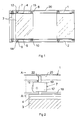
- Fig. 1 shows a device for removable covering of an opening according to a first embodiment of the invention.
- the opening is for example arranged in a building.
- the device comprises a top railing 1 intended to be mounted to an upper part of the opening and a bottom railing 2 intended to be mounted to a lower part of the opening.
- the top and the bottom railings 1, 2 are elongate and extend substantially horizontally along the opening.
- the railings 1, 2 are formed in some soft material, preferably some soft metal, for example aluminum.
- the sheets 3 are for example made of some transparent material such as glass or plastic, but can also be made by a non-transparent material such as a laminate.
- the sheets are arranged such that they together form a covering of the opening.
- the sheets form a wall together protecting against cold winds, rain and snow.
- the weather is sunny, it is desirable that the sheets of glass can be moved aside to let in sun and warmth.
- the sheet 3 is in its upper end provided with an upper supporting profile 4 carrying the sheet and the sheet is in its lower part provided with a lower supporting profile 5.
- the upper and the lower supporting profiles are fixedly mounted to the sheet and are preferably formed in aluminum.
- the upper supporting profile 4 is provided with a first and a second wheeling arrangement 7, 8 arranged to roll along the top railing 1.
- the lower supporting profile 5 is in the same way provided with two wheeling arrangements 9, 10 arranged to roll along the bottom railing.
- the first wheeling arrangement 7, 9 is arranged in one end of the supporting profile 4, 5.
- the second wheeling arrangement 8, 10 is fixedly mounted in the vicinity of the opposite end of the supporting profile. The distance between the end of the supporting profile and the second wheeling arrangement 8, 10 differ for different sheets 3.
- the sheet 3 is turnable about two hinge pins 12, 14 arranged in line with each other and perpendicular to the extension of the railings. The sheet 3 is thus turnable about an axis perpendicular to the length axis of the railings 1, 2.
- An upper hinge pin 12 extends from the upper supporting profile 4, through the wheeling arrangement 7 and into the top railing 1.
- a lower hinge pin 14 extends from the lower supporting profile 5, through the wheeling arrangement 9, and into the bottom railing 2.
- the top railing 1 is provided with an opening 15, through which the wheeling arrangement 8 can pass when turning the sheet 3.
- An analogous opening is arranged in the bottom railing 2.
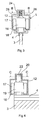
- Fig. 2 shows in closer detail the appearance of the wheeling arrangement 7 and the hinge pin 12.
- the wheeling arrangement 7 comprises two parallel wheels wherein one wheel 17 is visible in the figure. Further, the wheeling arrangement 7 comprises a body 19 upon which the wheels are suspended.
- the wheels run along a flange 18 extending along the top railing 1.
- a longitudinal groove 20 or a notch is arranged, extending along the entire length axis of the railing.
- the hinge pin 12 is pole shaped and is in its lower end fixed to the upper supporting profile 4 of the sheet 3 and comprises in its upper end a stopping member 22.
- the stopping member 22 extends into the groove 20 and is arranged to run along the groove when the sheet 3 is parallel to the railing 1.
- the body 19 is provided with a through-hole, intended to receive the hinge pin 12.
- the hinge pin 12 is arranged turnable in a relation to the body 19.
- the stopping member 22 constitutes the upper part of the hinge pin 12.
- the stopping member has a length axis coinciding with the length axis of the hinge pin.
- the stopping member is fixedly connected to or is a part of the hinge pin. Thus a turning of the hinge pin also causes a turning of the stopping member.
- the stopping member is made of a material, which is harder than the material of which the profile 1 is made, for example of steel.
- Fig. 3 shows a cross section through the profile 1 along a section A-A in fig. 2.
- the railing 1 comprises a protruding part 24, which extends along the entire length of the railing and has a substantially U-shaped cross section.
- the protruding part 24 comprises two parallel walls 26, 28, the insides of which are arranged to cooperate with the stopping member 22.
- the walls 26, 28 and the space between them form the groove 20.
- Fig. 4 shows how the stopping member 22 cooperates with the groove 20, when the sheet 3 stands at a 90 degrees angle in a relation to the top and bottom railings. Since the stopping member 22 is arranged fixedly in relation to the sheet 3, the stopping member is turned when the sheet 3 is turned.
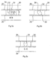
- Figs. 5a-5c show how the stopping member 22 is turned in relation to the groove 20 when the sheet is turned.
- Fig. 5a shows a section B-B through the protruding part 24 and the stopping member 22 in fig. 3.
- Fig. 5c shows a cross section C-C through the protruding part 24 and the stopping member 22 in fig. 4.
- the stopping member 22 has a first extension a along a first axis 32 through the stopping member and a second extension b along a second axis 34, which is perpendicular towards the first axis 32.
- the extension a is substantially smaller than the extension b.
- the extension a is about 4 mm and the extension b is about 6 mm.
- the groove 20 has a width c, which is larger than the first extension a of the stopping member and smaller than or equal to the second extension b of the stopping member.
- c is about 5,5 mm.
- the stopping member 22 is substantially cylinder shaped having two opposite, substantially planer faces and two opposite substantially convex faces.
- the hinge pin 12 and the stopping member is made from a screw, on which two opposite sides in the threaded end of the screw has been bevelled.
- the stopping member 22 comprises two opposite, substantially convex portions 29, 30, each of which having a convex surface intended to bear against the inside of the walls 26, 28 in the groove 20 when turning the sheet about the hinge pin 12.
- the convex portions 29, 30 are formed with a uniform radius, which is equal for both portions.
- the stopping member 22 is arranged such that it runs along the groove 20, with its first axis 22 substantially across the groove 20 when the sheet is substantially parallel with the railings.
- the stopping member 22 minimises the first extension a being smaller than the width c of the groove 20 the stopping member 22 and thus the sheet 3 runs easily along the railing 1, as long as the sheet is in parallel with the railings.
- the convex portions 28, 30 will contact the walls 26, 28.
- the stopping member 22 having a second extension b, which is equal to or somewhat larger than the width c of the groove 20 the stopping member 22 becomes locked from motion along the railing 20 when the sheet is turned in a relation to the railing.
- the convex portions 29, 30 being shaped with a uniform radius a turning about the length axis of the stopping member is allowed simultaneously and thus also about the length axis of the hinge pin.
- the convex portions 29, 30 are provided with threads in order for them to cut into the walls in the groove and to in such a way further lock the stopping member from motion along the railing.
- the convex portions may instead be provided with transverse notches.
- the stopping member 22 begins to lock when the convex portions 29, 30 makes contact with the walls 26, 28 of the railing 1. This means that the sheet 3 must be turned outwardly to a certain angle before the stopping member begins to lock from motion along the railing.
- the stopping member 22 will always be turned in relation to the railing in approximately the same position along the railing. This means that the walls in the groove at this position will at least partly be hollowed out and shaped by the turning motion of the stopping member. This means that it will be heavy the first times the sheet is turned but the more times the sheet has been turned the turning will be easier.
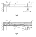
- the figures 6 and 7 show a device according to the invention seen from above.
- the railing 1 is provided with a guiding member 40 arranged with one face turned towards the sheet 3 during the beginning of the turning.
- the face comprises at least one section 42 having a concave surface, which is arranged to cooperate with some protruding part arranged on the upper part of the sheet.
- the face 42 cooperates with the wheeling arrangement 8.
- the guiding member 40 and the wheeling arrangement 8 are arranged in such a way that they are in contact with each other during the initial phase of the turning of the sheet and in such a way are prevented the sheet and the hinge pin from moving along the railing 1. Thanks to the concave surface 42 the guiding member 40 holds the sheet 3 in place during the entire initial phase of the turning.
Landscapes
- Engineering & Computer Science (AREA)
- Mechanical Engineering (AREA)
- Support Devices For Sliding Doors (AREA)
- Hinges (AREA)
- Tables And Desks Characterized By Structural Shape (AREA)
- Escalators And Moving Walkways (AREA)
Applications Claiming Priority (2)
| Application Number | Priority Date | Filing Date | Title |
|---|---|---|---|
| SE0302934A SE525730C2 (sv) | 2003-11-07 | 2003-11-07 | Hopfällbar täckning av en öppning |
| SE0302934 | 2003-11-07 |
Publications (1)
| Publication Number | Publication Date |
|---|---|
| EP1538292A2 true EP1538292A2 (de) | 2005-06-08 |
Family
ID=29707854
Family Applications (1)
| Application Number | Title | Priority Date | Filing Date |
|---|---|---|---|
| EP20040025011 Withdrawn EP1538292A2 (de) | 2003-11-07 | 2004-10-21 | Wegklappbare Abdeckung einer Öffnung |
Country Status (3)
| Country | Link |
|---|---|
| EP (1) | EP1538292A2 (de) |
| NO (1) | NO20044746L (de) |
| SE (1) | SE525730C2 (de) |
Cited By (3)
| Publication number | Priority date | Publication date | Assignee | Title |
|---|---|---|---|---|
| EP1889996A1 (de) | 2006-08-16 | 2008-02-20 | Lumon Oy | Paneelsystem und oberes Führungselement dafür |
| EP1892362A1 (de) | 2006-08-16 | 2008-02-27 | Lumon Oy | Paneelsystem und Steuerung der Verriegelung |
| SE541285C2 (en) * | 2016-11-09 | 2019-06-11 | Tbo Haglinds Ab | An opening device for a window in a glazed balcony and a window unit including the opening device |
-
2003
- 2003-11-07 SE SE0302934A patent/SE525730C2/sv not_active IP Right Cessation
-
2004
- 2004-10-21 EP EP20040025011 patent/EP1538292A2/de not_active Withdrawn
- 2004-11-02 NO NO20044746A patent/NO20044746L/no not_active Application Discontinuation
Cited By (4)
| Publication number | Priority date | Publication date | Assignee | Title |
|---|---|---|---|---|
| EP1889996A1 (de) | 2006-08-16 | 2008-02-20 | Lumon Oy | Paneelsystem und oberes Führungselement dafür |
| EP1892362A1 (de) | 2006-08-16 | 2008-02-27 | Lumon Oy | Paneelsystem und Steuerung der Verriegelung |
| EP1892362B1 (de) * | 2006-08-16 | 2014-09-17 | Lumon Invest Oy | Paneelsystem |
| SE541285C2 (en) * | 2016-11-09 | 2019-06-11 | Tbo Haglinds Ab | An opening device for a window in a glazed balcony and a window unit including the opening device |
Also Published As
| Publication number | Publication date |
|---|---|
| SE0302934L (sv) | 2005-04-12 |
| NO20044746L (no) | 2005-05-09 |
| SE525730C2 (sv) | 2005-04-12 |
| SE0302934D0 (sv) | 2003-11-07 |
Similar Documents
| Publication | Publication Date | Title |
|---|---|---|
| US5732756A (en) | Retractable awning with improved assembly features | |
| DE3605770A1 (de) | Trennwand, insbesondere fuer eine runddusche | |
| US10278547B2 (en) | Door assembly for a bathing enclosure | |
| CA2914942A1 (en) | Accordion shutter hinge assembly | |
| EP1498571A1 (de) | Sicherungsvorrichtung für eine Leiter | |
| EP0942141B1 (de) | Eckverbindung für einen Rahmen | |
| ES2355121T3 (es) | Inserto de cerradura para una cerradura de puerta de vidrio. | |
| US5419640A (en) | Adjustable support for journals and hinge pins, especially for use with doors and gates | |
| HU216417B (hu) | Vezetőszerkezettel rendelkező, eltolható elem | |
| EP2647780B1 (de) | Vorrichtung zum Befestigen von Platten mit einem gewissen Abstand von einer Struktur. | |
| US20180002948A1 (en) | Decorative railing with adjustable attaching block | |
| PT1060319E (pt) | Arranjo para a suspensão articulável e deslizável de parede | |
| EP1520955A2 (de) | Klemmträger für Sonnen- und Blickschutzeinrichtungen | |
| CA2265129A1 (en) | Corner assembly for a frame | |
| EP2160500A2 (de) | Umzäunungssystem | |
| EP1538283B1 (de) | Selbstrichtendes Zaunpanel mit Bügelbaluster | |
| DE102006019755A1 (de) | Freitragendes Vordach | |
| EP1889996B1 (de) | Paneelsystem und oberes Führungselement dafür | |
| JP3577251B2 (ja) | 伸縮門扉におけるキャスター受け金具のキャップ構造 | |
| CN2511518Y (zh) | 一种汽车遮阳帘 | |
| JP3786612B2 (ja) | フェンス | |
| EP2148030A1 (de) | Feststellvorrichtung für einen Fensterflügel | |
| SE525730C2 (sv) | Hopfällbar täckning av en öppning | |
| JPH0725431Y2 (ja) | 目隠し用部材 | |
| KR200447814Y1 (ko) | 곡률가변형 거울 |
Legal Events
| Date | Code | Title | Description |
|---|---|---|---|
| PUAI | Public reference made under article 153(3) epc to a published international application that has entered the european phase |
Free format text: ORIGINAL CODE: 0009012 |
|
| AK | Designated contracting states |
Kind code of ref document: A2 Designated state(s): AT BE BG CH CY CZ DE DK EE ES FI FR GB GR HU IE IT LI LU MC NL PL PT RO SE SI SK TR |
|
| AX | Request for extension of the european patent |
Extension state: AL HR LT LV MK |
|
| STAA | Information on the status of an ep patent application or granted ep patent |
Free format text: STATUS: THE APPLICATION IS DEEMED TO BE WITHDRAWN |
|
| 18D | Application deemed to be withdrawn |
Effective date: 20090505 |