EP1538286A1 - Schliesszylinder - Google Patents
Schliesszylinder Download PDFInfo
- Publication number
- EP1538286A1 EP1538286A1 EP04292835A EP04292835A EP1538286A1 EP 1538286 A1 EP1538286 A1 EP 1538286A1 EP 04292835 A EP04292835 A EP 04292835A EP 04292835 A EP04292835 A EP 04292835A EP 1538286 A1 EP1538286 A1 EP 1538286A1
- Authority
- EP
- European Patent Office
- Prior art keywords
- barrel
- key
- door
- lug
- front face
- Prior art date
- Legal status (The legal status is an assumption and is not a legal conclusion. Google has not performed a legal analysis and makes no representation as to the accuracy of the status listed.)
- Granted
Links
Images

Classifications
-
- E—FIXED CONSTRUCTIONS
- E05—LOCKS; KEYS; WINDOW OR DOOR FITTINGS; SAFES
- E05B—LOCKS; ACCESSORIES THEREFOR; HANDCUFFS
- E05B47/00—Operating or controlling locks or other fastening devices by electric or magnetic means
- E05B47/0038—Operating or controlling locks or other fastening devices by electric or magnetic means using permanent magnets
-
- E—FIXED CONSTRUCTIONS
- E05—LOCKS; KEYS; WINDOW OR DOOR FITTINGS; SAFES
- E05B—LOCKS; ACCESSORIES THEREFOR; HANDCUFFS
- E05B27/00—Cylinder locks or other locks with tumbler pins or balls that are set by pushing the key in
- E05B27/02—Cylinder locks or other locks with tumbler pins or balls that are set by pushing the key in operated by the edge of the key
- E05B27/08—Cylinder locks or other locks with tumbler pins or balls that are set by pushing the key in operated by the edge of the key arranged axially
-
- E—FIXED CONSTRUCTIONS
- E05—LOCKS; KEYS; WINDOW OR DOOR FITTINGS; SAFES
- E05B—LOCKS; ACCESSORIES THEREFOR; HANDCUFFS
- E05B35/00—Locks for use with special keys or a plurality of keys ; keys therefor
- E05B35/008—Locks for use with special keys or a plurality of keys ; keys therefor for simple tool-like keys
Definitions
- the invention relates to a lock cylinder.
- the invention also relates to a key adapted to such a cylinder, an assembly comprising such a cylinder and such a key and a door on which is adapted such a set. It finds application in the locks for doors, in particular for elevator landing doors and freight elevator.
- Elevator landing door locks are already known which locks and unlocks with a special key that adapts to a particular device called "European triangle” described in European standard EN81 in Annex A.
- European standard EN81 in Annex A European standard EN81 in Annex A.
- the rotation the "European triangle” makes it possible to lock / unlock the lock and thus condemn / unclamp the landing doors especially at the time of the maintenance of the elevator.
- Normally the use of this lock is reserved for maintenance technician who must use the special key to unlock the lock at the beginning of the intervention.
- the lock is replaced in the locking position. Indeed a spring recalls the "European triangle” or the lock in position of locking, which causes an automatic locking of the lock.
- An object of the present invention is to provide a lock cylinder which does not does not have the disadvantages of the prior art.
- a lock cylinder comprising a front face, a movable pin between a rest position and an operating position characterized in that in the rest position the lug is flush with the front face of the barrel and in the operating position the lug protrudes from the front face of the barrel.
- the barrel comprises a suitable device to pass and maintain the pin in operating position.
- the lug is constrained by a restoring force in the position of rest.
- the barrel comprises a device adapted to keep the pin in the rest position.
- the lug is constrained by a restoring force in the position of operation.
- the lug is partly made of a magnetic material and the device is a magnetic field generator.
- the rear face of the barrel is pierced with a hole adapted to a European triangle.
- the invention also proposes a key for the lock of a door comprising a barrel according to one of the preceding variants, characterized in that the key comprises a surface adapted to come into contact with the front face of the barrel and in that this surface is provided with housings adapted to receive the lug when it is in operating position.
- the key comprises a device adapted to pass and keep the pin in the operating position.
- the device is a magnetic field generator, such as a magnet or an electromagnet.
- the key includes a battery for powering the device.
- the battery is connected to a discharge circuit.
- the battery is rechargeable by an electric charger which delivers a specific pulse train
- the key is provided with charging stations, a pulse train recognition device and a device allowing the recharging the battery and if the recognition device identifies the train pulses, the device allowing the charging allows the battery to be recharged by the charger.
- the invention also proposes an assembly characterized in that it comprises a barrel and a key according to one of the preceding variants.
- the points of application of the forces exerted on the barrel by the key are distant from the axis X of rotation of the barrel.
- the device generates or cuts the magnetic field after a recognition phase without contact between the barrel and the key.
- the device generates the magnetic field during closure an electrical circuit between the key and the barrel.
- the closure of the electrical circuit is achieved by the implementation of contact of the terminals of the key and the terminals of the barrel.
- the shape and / or the position of the terminals makes a polarizer.
- the invention also proposes a door on which is adapted a barrel assembly and key according to one of the preceding variants, characterized in that the door is provided a hole whose diameter is the diameter of the barrel.
- the diameter of the bore is the diameter of the key.
- the front face of the barrel is flush or recessed by relative to the front surface of the door.
- the door is an elevator landing door.
- the rear face of the barrel is connected to a lock.
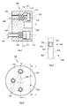
- Fig. 1 has a barrel 100 of generally cylindrical shape, which comprises a front face 102 and a rear face 104.
- the front face 102 is visible and turned towards the technician and the rear face 104 is not visible to the technician and is connected to a lock 504 for condemn / unlock the door.
- Erodes 106 have been placed in the recesses 112.
- the lugs 106 can move in translation parallel to the axis of the barrel 100 inside the recesses 112 between a rest position 108 and an operating position 110.
- the displacement pins 106 is limited by a shoulder 114 which abuts against the wall before 117 and the rear wall 116 of the recesses 112.
- the construction of the barrel 100 so is simple.
- the rear wall 116 may also be the wall of the door against which the cylinder 100 rests.
- FIG. 1 one of the lugs 106 has been shown in the rest position 108 and another in an operating position 110 to facilitate understanding.
- the lugs 106 are flush with the front face 102 of the barrel 100.
- the front face 102 is therefore smooth and has no possible catch in particular on the pins 106 to rotate the barrel 100.
- the security is therefore reinforced because it is necessary to have a key adapted to rotate the barrel 100.
- the use of a tool can not damage the cylinder 100 because no part can be hooked by the tool.
- the lugs 106 In the operating position 110, the lugs 106 partially come out of the barrel 100 and are therefore salient with respect to the face 102 of the cylinder 100.
- the lugs 106 When the lugs 106 are out of the barrel 100, it is possible to build on them to make turn the barrel 100 about an axis X perpendicular to the front face 102, which causes locking / unlocking of the lock 504.
- the X axis is preferably the axis of symmetry of the barrel 100.
- the technician can push the pins 106 by hand but it is advantageous to constrain the lugs 106 in rest position 108 by a recall force.
- the force can be created by helical springs 118 mounted concentric on the lugs 106 between the front wall 117 of the recesses 112 and the shoulders 114 of the lugs 106.
- the body 401 contains the other elements of key 400 which will be described later.
- a handle 403 At one end of the body 401 is disposed a handle 403 to facilitate the handling of the key 400 by the user, at the other end is disposed on a surface 402.
- the surface 402 is provided with housings 404 adapted to position and shaped to receive the pins 106 when in position operation 110.
- the method of locking / unlocking a door comprises a step contacting the surface 402 of the key 400 with the front face 102 of the barrel 100; a step of facing the lugs 106 with the housings 404; a step operating position 110 of the pins 106 and their penetration into dwellings 404; a 400 key rotation step to lock / unlock the door; a step of removing the key 400 and a return step in the rest position 108 pins.
- the step of facing the pins 106 with the housings 404 and the step of rotation of the key 400 to lock / unlock the door are made by rotation of the key 400 around the X axis.
- the drive of the cylinder 100 by the key 400 is ensured by the cooperation between the lugs 106 and the housings 404.
- the shape and / or the number of lugs 106 must therefore be adapted to allow the drive in rotation.
- To drive the barrel It is not necessary that the points of application of the forces exerted on the barrel 100 by key 400 are on the X axis.
- the setting in the operating position 110 of the lugs 106 can be done by any device 406 capable of attracting the pins 106 inside the housing 404 or the push out of the recesses 112.
- the device 406 may be a magnetic field device housed in the barrel or in the key, a suction device housed in the key, a mechanism to cams housed in the barrel and including a motor and cams to push the pins.
- the lugs 106 are at least partly made of a magnetic material.
- the key 400 is provided a magnetic field generator 406.
- the magnetic field must be adapted the magnetic properties of the pins 106 to be able to attract them.
- the generator 406 can be a magnet or an electromagnet.
- the magnetic field generator 406 can also be arranged in the barrel 100.
- the generator 406 can then be provided to attract the pins 106 or repel according to whether it is located on one side or the other of the lugs 106.
- the generator 406 housed in the barrel 100 can be provided to continuously generate a magnetic field that maintains the pins 106 in the rest position 108. The transition to the operating position 110 is then done by stopping the magnetic field, the springs 118 are then provided for create a restoring force that pushes the pins 106 out of the barrel 100.
- This mode allows doors to be opened when there is a power outage, making it easier to the intervention of helpers who can use a tool to unlock the doors.
- the magnetic field is generated again the pins 106 are replaced in rest position 108 by the magnetic field.
- the generator 406 only generates or cuts the magnetic field when the key 400 is in front of the barrel 100.
- the generator 406 When the generator 406 is an electromagnet, it is powered by a battery 408.
- the battery 408 can to be in fact a general power supply for all equipped doors or a charger to allow the door to open even in the event of a power failure.
- the battery 408 will also be housed in the key 400 to facilitate the use of the key 400 by a technician of maintenance.
- a conventional switch on the key 400 can be used to turn on the generator 406 and created the magnetic field.
- the generator 406 is a winding which under the action of the Current flowing through it creates a magnetic field.
- One of the winding terminals 406 is connected to one of the terminals of the battery 408 by a wire 407, the other terminal of the 408 battery is connected to a wire 409 whose free end 414 is flush with the surface 402 of key 400.
- the other terminal of winding 406 is connected to another wire 410 whose free end 412 also comes flush with the surface 402.
- the device forms then an open circuit between the two ends 412, 414 which form the terminals of the circuit.
- the generator 406 and the battery 408 are then in a configuration such that no current flows and therefore no magnetic field is generated.
- two terminals 301, 302 are disposed of flush with the front face 102 so as not to be able to serve as fulcrum to rotate the barrel 100.
- the terminals 301, 302 are connected between they by a wire 201 to form an open loop.
- the thread 201 is embedded in the barrel 100, but it can also be a material track conductor positioned on the front face 102 of the barrel 100.
- the terminals 301, 302 are arranged so that when the key 400 is put in vis-à-vis the barrel 100, they come in contact respectively with the terminals 412, 414 of the key 400, thus achieving a closed circuit.
- the 408 battery delivers current in the coil 406 creating a magnetic field that attracts the pins 106 placing them in the operating position 110.
- the positioning of the various terminals 412, 414, 301, 302 will be determined from so that the lugs 106 are in front of the recesses 404 to allow the penetration of the pins 106 in the key 400.
- the positioning of the terminals 412, 414, 301, 302 will be chosen to serve as visual key to the technician who will position the key 400 on the cylinder 100. On may for example position the terminals on the same side of the device relative to a diameter of the barrel 100.
- the shape of the terminals may also facilitate the installation of the key 400 and improve the contact between the terminals 412, 414, 301, 302. For example, making recesses or excrescences in the terminals 301, 302 of the barrel 100 and excrescences or complementary recesses in terminals 412, 414 of the key 400.
- the penetration of the growths in the recesses will facilitate the positioning of the barrel 100 and the key 400 and will avoid that the circuit that allows the power supply opens when the key 400 is turned.
- recesses and growths should be of sufficiently small size not to not be able to be used to rotate the barrel with a tool.
- the shape and / or the position of the terminals thus makes a polarizer which facilitates the positioning of the key 400 by the user.
- the battery 408 is then connected to a discharge circuit that slowly empties it and renders it inoperative after of a certain time.
- the battery 408 must be able to be recharged by the authorized technician.
- the key 400 is then provided with a pulse train recognition device and a device allowing the charging of the battery 408. If the recognition device identifies the pulse train, the device allowing the charging allows the battery 408 to recharge on the charger that has been identified as a charger authorized.
- transponder between the key 400 and the charger, or any other code device that enhances security.
- Fig. 5 shows a section of a door 500 equipped with a cylinder 100 according to the invention.
- the barrel 100 is mounted free to rotate on the leaf or on the frame Door.
- the door 500 comprises a front surface 502 directed outwards and accessible from the outside and a rear surface 503 directed inwards and inaccessible from the outside as long as the door is closed.
- the door 500 also comprises a bore 501 of generally cylindrical shape in which the barrel 100 is put in place.
- the diameter of the bore 501 is greater or equal to the diameter of the cylinder 100 to allow a correct placement of the barrel 100.
- the front face 102 remains visible from the outside and the rear face 104 is connected to the lock 504.
- the diameter of the bore 501 is such that there is no space sufficient between the edges of the barrel 100 and the bore 501 to allow the rotation of the barrel by a tool.
- the front face 102 of the cylinder 100 is flush or recessed relative to the surface 102 of the door 500 to prevent the cylinder 100 has a surface can be used to fix a tool and make it possible to turn the barrel 100 and thus to lock / unlock lock 504.
- the diameter of the bore 501 is greater than or equal to the diameter of the key 400 to allow the insertion of the latter into the bore.
- the diameter of the bore 501 is equal to the diameter of the key 400 to help guide the the latter during its implementation and its rotation.
- the door can be an elevator landing door which must remain closed as long as the cabin is not positioned in front of the door, to prevent the door from opening the void.
- the barrel 100 is an element that can be mounted originally, that is to say that the lock 504 is adapted to the cylinder 100, but the barrel 100 can also be used to doors already in use that are locked / unlocked by a "triangle" "The rear face 104 of the barrel 100 is then pierced with a hole 200, represented in dotted line in FIG. 3, adapted to the shape of the "European triangle". During the introduction of the cylinder 100, the "European triangle” sinks into the hole 200 and the rotation of the barrel 100 then drives the rotation of the "European triangle”. Of the glue can be applied between hole 200 of barrel 100 and the European triangle for enhance security and prevent the cylinder 100 can be easily removed.
- a keying element can be made between the key 400 and the piercing 501 of the door or the cylinder 100 by all forms that facilitate the positioning lugs 106 opposite the recesses 404.
- the steps of contacting the surface 402 with the front face 102 and facing the pins 106 with the 404 housing by rotation will then simultaneously. Shapes must not allow a tool to build on them to turn the barrel 100.
- the magnetic field generator 406 can be implanted in the lugs 106 and the magnet can be in the key 400 or in the barrel 100.
- the generation or the cutting of the magnetic field of the pins 106 drives their displacement because the magnet is fixed.
- the pins 106 do not need to be made in a magnetic material, this helps to enhance safety because even the use a very powerful magnet can not attract the lugs 106 out of the barrel 100, the power supply of the generator 406 can then be done only after a phase of recognition between the barrel 100 and the key 400.
Landscapes
- Lock And Its Accessories (AREA)
- Centrifugal Separators (AREA)
- Confectionery (AREA)
- Fluid-Damping Devices (AREA)
- Lubrication Of Internal Combustion Engines (AREA)
Applications Claiming Priority (2)
| Application Number | Priority Date | Filing Date | Title |
|---|---|---|---|
| FR0314314A FR2863296B1 (fr) | 2003-12-05 | 2003-12-05 | Barillet pour serrure |
| FR0314314 | 2003-12-05 |
Publications (2)
| Publication Number | Publication Date |
|---|---|
| EP1538286A1 true EP1538286A1 (de) | 2005-06-08 |
| EP1538286B1 EP1538286B1 (de) | 2008-04-16 |
Family
ID=34451732
Family Applications (1)
| Application Number | Title | Priority Date | Filing Date |
|---|---|---|---|
| EP04292835A Expired - Lifetime EP1538286B1 (de) | 2003-12-05 | 2004-11-30 | Schliesszylinder |
Country Status (5)
| Country | Link |
|---|---|
| EP (1) | EP1538286B1 (de) |
| AT (1) | ATE392523T1 (de) |
| DE (1) | DE602004013109T2 (de) |
| ES (1) | ES2305689T3 (de) |
| FR (1) | FR2863296B1 (de) |
Citations (7)
| Publication number | Priority date | Publication date | Assignee | Title |
|---|---|---|---|---|
| DE2200517A1 (de) * | 1972-01-05 | 1973-07-12 | Mrt Magnet Regeltechnik Gmbh | Magnetisch arbeitende sperr- oder steuervorrichtung |
| US3837195A (en) * | 1973-02-08 | 1974-09-24 | E Pelto | Magnetic pin lock |
| WO1987003923A1 (en) * | 1985-12-17 | 1987-07-02 | Krister Juntunen | Cylinder lock |
| US5033696A (en) * | 1989-12-15 | 1991-07-23 | Rockwell International Corporation | Flush mounted hatch opener |
| US5605065A (en) * | 1993-07-07 | 1997-02-25 | Lopez-Casals; Jesus | Magnetic controlled locking apparatus |
| FR2763084A1 (fr) * | 1997-05-07 | 1998-11-13 | Metallurg Haut Marnaise Soc | Dispositif d'inviolabilite pour les carres de manoeuvre des poteaux ou bouches a incendie et poteau d'incendie, bouche d'incendie et coffre de poteau d'incendie ainsi equipes |
| US20020029596A1 (en) * | 2000-04-28 | 2002-03-14 | Antonio Tallarico | Safety pin to be actuated by a magnetic key |
-
2003
- 2003-12-05 FR FR0314314A patent/FR2863296B1/fr not_active Expired - Fee Related
-
2004
- 2004-11-30 EP EP04292835A patent/EP1538286B1/de not_active Expired - Lifetime
- 2004-11-30 ES ES04292835T patent/ES2305689T3/es not_active Expired - Lifetime
- 2004-11-30 AT AT04292835T patent/ATE392523T1/de not_active IP Right Cessation
- 2004-11-30 DE DE602004013109T patent/DE602004013109T2/de not_active Expired - Fee Related
Patent Citations (7)
| Publication number | Priority date | Publication date | Assignee | Title |
|---|---|---|---|---|
| DE2200517A1 (de) * | 1972-01-05 | 1973-07-12 | Mrt Magnet Regeltechnik Gmbh | Magnetisch arbeitende sperr- oder steuervorrichtung |
| US3837195A (en) * | 1973-02-08 | 1974-09-24 | E Pelto | Magnetic pin lock |
| WO1987003923A1 (en) * | 1985-12-17 | 1987-07-02 | Krister Juntunen | Cylinder lock |
| US5033696A (en) * | 1989-12-15 | 1991-07-23 | Rockwell International Corporation | Flush mounted hatch opener |
| US5605065A (en) * | 1993-07-07 | 1997-02-25 | Lopez-Casals; Jesus | Magnetic controlled locking apparatus |
| FR2763084A1 (fr) * | 1997-05-07 | 1998-11-13 | Metallurg Haut Marnaise Soc | Dispositif d'inviolabilite pour les carres de manoeuvre des poteaux ou bouches a incendie et poteau d'incendie, bouche d'incendie et coffre de poteau d'incendie ainsi equipes |
| US20020029596A1 (en) * | 2000-04-28 | 2002-03-14 | Antonio Tallarico | Safety pin to be actuated by a magnetic key |
Also Published As
| Publication number | Publication date |
|---|---|
| EP1538286B1 (de) | 2008-04-16 |
| ES2305689T3 (es) | 2008-11-01 |
| DE602004013109T2 (de) | 2009-06-10 |
| DE602004013109D1 (de) | 2008-05-29 |
| ATE392523T1 (de) | 2008-05-15 |
| FR2863296B1 (fr) | 2006-03-03 |
| FR2863296A1 (fr) | 2005-06-10 |
Similar Documents
| Publication | Publication Date | Title |
|---|---|---|
| EP0619628B1 (de) | Elektrische Verbinder insbesondere Verbinder zum Laden von Akkus | |
| EP1820722B2 (de) | Automatische System zur Speicherung von Fahrrädern | |
| FR2785638A1 (fr) | Serrure de porte a condamnation/decondamnation electrique exterieure et/ou interieur pour vehicule automobile | |
| EP0290330A1 (de) | Elektronisches Schloss | |
| EP4112855B1 (de) | Verfahren zum auswerfen eines flush-griffs unter frostbedingungen | |
| EP3220362B1 (de) | Anornung zum entriegeln einer zugangstür zu einem raum | |
| FR2918695A1 (fr) | Trappe equipee d'au moins une gache de verrouillage capable d'etre actionnee de chaque cote de la trappe. | |
| EP3477023A1 (de) | Schloss und schlüssel für dieses schloss | |
| FR2761396A1 (fr) | Serrure a commande electronique | |
| EP1538286B1 (de) | Schliesszylinder | |
| EP0811738A1 (de) | Verriegelungsvorrichtung | |
| EP0085690A1 (de) | Panikschloss mit elektrischer verriegelung | |
| EP2526244A1 (de) | Fahrzeugaussenhülle und vorrichtung zum verschliessen der tür in geschlossener stellung | |
| CH666369A5 (fr) | Appareil interrupteur d'urgence commandant un interrupteur electrique. | |
| EP2148027A1 (de) | Elektromechanische Verriegelungsvorrichtung | |
| FR2808552A1 (fr) | Serrure a deverrouillage mecanique et electrique | |
| FR2998102A1 (fr) | Prise electrique femelle, notamment destinee a la charge de vehicules electriques | |
| EP1460018A1 (de) | Steuerung für das Notentriegelungsgerät einer Aufzugsschachttür | |
| EP1040243B1 (de) | Elektrische steuerungsvorrichtung zur entriegelung einer drehenden welle, insbesondere eines schlosses und schloss mit solcher vorrichtung | |
| EP4410653B1 (de) | Abnehmbare stromversorgungseinheit und fahrzeug mit geschützten verbindungsanschlüssen | |
| WO2021116346A1 (fr) | Dispositif d'accès de secours d'ouvrant de véhicule à bobine de détection de position | |
| FR2767853A1 (fr) | Ensemble de cles et de serrures et applications a des antivols urbains pour cycles | |
| EP3477027A1 (de) | Einheit aus einem elektronischen schloss und einem elektronischen schlüssel | |
| FR2903447A1 (fr) | Ensemble a moteur d'entrainement en translation d'un portail coulissant pourvu de moyens de desacouplement des crabots entrainant le portail en translation | |
| EP1672746B1 (de) | Steckdose ausgerüstet mit zusätzlichem Sicherungsmittel |
Legal Events
| Date | Code | Title | Description |
|---|---|---|---|
| PUAI | Public reference made under article 153(3) epc to a published international application that has entered the european phase |
Free format text: ORIGINAL CODE: 0009012 |
|
| AK | Designated contracting states |
Kind code of ref document: A1 Designated state(s): AT BE BG CH CY CZ DE DK EE ES FI FR GB GR HU IE IS IT LI LU MC NL PL PT RO SE SI SK TR |
|
| AX | Request for extension of the european patent |
Extension state: AL HR LT LV MK YU |
|
| 17P | Request for examination filed |
Effective date: 20051021 |
|
| AKX | Designation fees paid |
Designated state(s): AT BE BG CH CY CZ DE DK EE ES FI FR GB GR HU IE IS IT LI LU MC NL PL PT RO SE SI SK TR |
|
| 17Q | First examination report despatched |
Effective date: 20060908 |
|
| GRAP | Despatch of communication of intention to grant a patent |
Free format text: ORIGINAL CODE: EPIDOSNIGR1 |
|
| GRAS | Grant fee paid |
Free format text: ORIGINAL CODE: EPIDOSNIGR3 |
|
| GRAA | (expected) grant |
Free format text: ORIGINAL CODE: 0009210 |
|
| AK | Designated contracting states |
Kind code of ref document: B1 Designated state(s): AT BE BG CH CY CZ DE DK EE ES FI FR GB GR HU IE IS IT LI LU MC NL PL PT RO SE SI SK TR |
|
| REG | Reference to a national code |
Ref country code: CH Ref legal event code: NV Representative=s name: ROTTMANN, ZIMMERMANN + PARTNER AG Ref country code: CH Ref legal event code: EP |
|
| REG | Reference to a national code |
Ref country code: IE Ref legal event code: FG4D Free format text: LANGUAGE OF EP DOCUMENT: FRENCH |
|
| REF | Corresponds to: |
Ref document number: 602004013109 Country of ref document: DE Date of ref document: 20080529 Kind code of ref document: P |
|
| PG25 | Lapsed in a contracting state [announced via postgrant information from national office to epo] |
Ref country code: SI Free format text: LAPSE BECAUSE OF FAILURE TO SUBMIT A TRANSLATION OF THE DESCRIPTION OR TO PAY THE FEE WITHIN THE PRESCRIBED TIME-LIMIT Effective date: 20080416 |
|
| PG25 | Lapsed in a contracting state [announced via postgrant information from national office to epo] |
Ref country code: PT Free format text: LAPSE BECAUSE OF FAILURE TO SUBMIT A TRANSLATION OF THE DESCRIPTION OR TO PAY THE FEE WITHIN THE PRESCRIBED TIME-LIMIT Effective date: 20080916 Ref country code: FI Free format text: LAPSE BECAUSE OF FAILURE TO SUBMIT A TRANSLATION OF THE DESCRIPTION OR TO PAY THE FEE WITHIN THE PRESCRIBED TIME-LIMIT Effective date: 20080416 Ref country code: BG Free format text: LAPSE BECAUSE OF FAILURE TO SUBMIT A TRANSLATION OF THE DESCRIPTION OR TO PAY THE FEE WITHIN THE PRESCRIBED TIME-LIMIT Effective date: 20080716 |
|
| REG | Reference to a national code |
Ref country code: ES Ref legal event code: FG2A Ref document number: 2305689 Country of ref document: ES Kind code of ref document: T3 |
|
| PG25 | Lapsed in a contracting state [announced via postgrant information from national office to epo] |
Ref country code: PL Free format text: LAPSE BECAUSE OF FAILURE TO SUBMIT A TRANSLATION OF THE DESCRIPTION OR TO PAY THE FEE WITHIN THE PRESCRIBED TIME-LIMIT Effective date: 20080416 |
|
| REG | Reference to a national code |
Ref country code: IE Ref legal event code: FD4D |
|
| PG25 | Lapsed in a contracting state [announced via postgrant information from national office to epo] |
Ref country code: IS Free format text: LAPSE BECAUSE OF FAILURE TO SUBMIT A TRANSLATION OF THE DESCRIPTION OR TO PAY THE FEE WITHIN THE PRESCRIBED TIME-LIMIT Effective date: 20080816 |
|
| PG25 | Lapsed in a contracting state [announced via postgrant information from national office to epo] |
Ref country code: DK Free format text: LAPSE BECAUSE OF FAILURE TO SUBMIT A TRANSLATION OF THE DESCRIPTION OR TO PAY THE FEE WITHIN THE PRESCRIBED TIME-LIMIT Effective date: 20080416 Ref country code: CZ Free format text: LAPSE BECAUSE OF FAILURE TO SUBMIT A TRANSLATION OF THE DESCRIPTION OR TO PAY THE FEE WITHIN THE PRESCRIBED TIME-LIMIT Effective date: 20080416 Ref country code: IE Free format text: LAPSE BECAUSE OF FAILURE TO SUBMIT A TRANSLATION OF THE DESCRIPTION OR TO PAY THE FEE WITHIN THE PRESCRIBED TIME-LIMIT Effective date: 20080416 Ref country code: SE Free format text: LAPSE BECAUSE OF FAILURE TO SUBMIT A TRANSLATION OF THE DESCRIPTION OR TO PAY THE FEE WITHIN THE PRESCRIBED TIME-LIMIT Effective date: 20080716 |
|
| PLBE | No opposition filed within time limit |
Free format text: ORIGINAL CODE: 0009261 |
|
| STAA | Information on the status of an ep patent application or granted ep patent |
Free format text: STATUS: NO OPPOSITION FILED WITHIN TIME LIMIT |
|
| PG25 | Lapsed in a contracting state [announced via postgrant information from national office to epo] |
Ref country code: RO Free format text: LAPSE BECAUSE OF FAILURE TO SUBMIT A TRANSLATION OF THE DESCRIPTION OR TO PAY THE FEE WITHIN THE PRESCRIBED TIME-LIMIT Effective date: 20080416 Ref country code: SK Free format text: LAPSE BECAUSE OF FAILURE TO SUBMIT A TRANSLATION OF THE DESCRIPTION OR TO PAY THE FEE WITHIN THE PRESCRIBED TIME-LIMIT Effective date: 20080416 |
|
| 26N | No opposition filed |
Effective date: 20090119 |
|
| PG25 | Lapsed in a contracting state [announced via postgrant information from national office to epo] |
Ref country code: EE Free format text: LAPSE BECAUSE OF FAILURE TO SUBMIT A TRANSLATION OF THE DESCRIPTION OR TO PAY THE FEE WITHIN THE PRESCRIBED TIME-LIMIT Effective date: 20080416 |
|
| BERE | Be: lapsed |
Owner name: THYSSENKRUPP ELEVATOR MANUFACTURING FRANCE S.A.S. Effective date: 20081130 |
|
| PG25 | Lapsed in a contracting state [announced via postgrant information from national office to epo] |
Ref country code: MC Free format text: LAPSE BECAUSE OF NON-PAYMENT OF DUE FEES Effective date: 20081130 |
|
| REG | Reference to a national code |
Ref country code: CH Ref legal event code: PL |
|
| GBPC | Gb: european patent ceased through non-payment of renewal fee |
Effective date: 20081130 |
|
| PG25 | Lapsed in a contracting state [announced via postgrant information from national office to epo] |
Ref country code: NL Free format text: LAPSE BECAUSE OF NON-PAYMENT OF DUE FEES Effective date: 20090601 |
|
| NLV4 | Nl: lapsed or anulled due to non-payment of the annual fee |
Effective date: 20090601 |
|
| PG25 | Lapsed in a contracting state [announced via postgrant information from national office to epo] |
Ref country code: IT Free format text: LAPSE BECAUSE OF NON-PAYMENT OF DUE FEES Effective date: 20081130 |
|
| PG25 | Lapsed in a contracting state [announced via postgrant information from national office to epo] |
Ref country code: CY Free format text: LAPSE BECAUSE OF FAILURE TO SUBMIT A TRANSLATION OF THE DESCRIPTION OR TO PAY THE FEE WITHIN THE PRESCRIBED TIME-LIMIT Effective date: 20080416 Ref country code: BE Free format text: LAPSE BECAUSE OF NON-PAYMENT OF DUE FEES Effective date: 20081130 |
|
| PG25 | Lapsed in a contracting state [announced via postgrant information from national office to epo] |
Ref country code: CH Free format text: LAPSE BECAUSE OF NON-PAYMENT OF DUE FEES Effective date: 20081130 Ref country code: DE Free format text: LAPSE BECAUSE OF NON-PAYMENT OF DUE FEES Effective date: 20090603 Ref country code: LI Free format text: LAPSE BECAUSE OF NON-PAYMENT OF DUE FEES Effective date: 20081130 |
|
| PG25 | Lapsed in a contracting state [announced via postgrant information from national office to epo] |
Ref country code: GB Free format text: LAPSE BECAUSE OF NON-PAYMENT OF DUE FEES Effective date: 20081130 |
|
| REG | Reference to a national code |
Ref country code: ES Ref legal event code: FD2A Effective date: 20081201 |
|
| PG25 | Lapsed in a contracting state [announced via postgrant information from national office to epo] |
Ref country code: AT Free format text: LAPSE BECAUSE OF NON-PAYMENT OF DUE FEES Effective date: 20081130 |
|
| PG25 | Lapsed in a contracting state [announced via postgrant information from national office to epo] |
Ref country code: ES Free format text: LAPSE BECAUSE OF NON-PAYMENT OF DUE FEES Effective date: 20081201 |
|
| PG25 | Lapsed in a contracting state [announced via postgrant information from national office to epo] |
Ref country code: LU Free format text: LAPSE BECAUSE OF NON-PAYMENT OF DUE FEES Effective date: 20081130 Ref country code: HU Free format text: LAPSE BECAUSE OF FAILURE TO SUBMIT A TRANSLATION OF THE DESCRIPTION OR TO PAY THE FEE WITHIN THE PRESCRIBED TIME-LIMIT Effective date: 20081017 |
|
| PG25 | Lapsed in a contracting state [announced via postgrant information from national office to epo] |
Ref country code: TR Free format text: LAPSE BECAUSE OF FAILURE TO SUBMIT A TRANSLATION OF THE DESCRIPTION OR TO PAY THE FEE WITHIN THE PRESCRIBED TIME-LIMIT Effective date: 20080416 |
|
| PG25 | Lapsed in a contracting state [announced via postgrant information from national office to epo] |
Ref country code: GR Free format text: LAPSE BECAUSE OF FAILURE TO SUBMIT A TRANSLATION OF THE DESCRIPTION OR TO PAY THE FEE WITHIN THE PRESCRIBED TIME-LIMIT Effective date: 20080717 |
|
| PGFP | Annual fee paid to national office [announced via postgrant information from national office to epo] |
Ref country code: FR Payment date: 20111214 Year of fee payment: 8 |
|
| REG | Reference to a national code |
Ref country code: FR Ref legal event code: ST Effective date: 20130731 |
|
| PG25 | Lapsed in a contracting state [announced via postgrant information from national office to epo] |
Ref country code: FR Free format text: LAPSE BECAUSE OF NON-PAYMENT OF DUE FEES Effective date: 20121130 |