EP0811738A1 - Verriegelungsvorrichtung - Google Patents
Verriegelungsvorrichtung Download PDFInfo
- Publication number
- EP0811738A1 EP0811738A1 EP97490017A EP97490017A EP0811738A1 EP 0811738 A1 EP0811738 A1 EP 0811738A1 EP 97490017 A EP97490017 A EP 97490017A EP 97490017 A EP97490017 A EP 97490017A EP 0811738 A1 EP0811738 A1 EP 0811738A1
- Authority
- EP
- European Patent Office
- Prior art keywords
- blade
- projection
- locking
- housing
- fixed member
- Prior art date
- Legal status (The legal status is an assumption and is not a legal conclusion. Google has not performed a legal analysis and makes no representation as to the accuracy of the status listed.)
- Withdrawn
Links
Images


Classifications
-
- E—FIXED CONSTRUCTIONS
- E05—LOCKS; KEYS; WINDOW OR DOOR FITTINGS; SAFES
- E05B—LOCKS; ACCESSORIES THEREFOR; HANDCUFFS
- E05B47/00—Operating or controlling locks or other fastening devices by electric or magnetic means
-
- E—FIXED CONSTRUCTIONS
- E05—LOCKS; KEYS; WINDOW OR DOOR FITTINGS; SAFES
- E05B—LOCKS; ACCESSORIES THEREFOR; HANDCUFFS
- E05B47/00—Operating or controlling locks or other fastening devices by electric or magnetic means
- E05B47/0001—Operating or controlling locks or other fastening devices by electric or magnetic means with electric actuators; Constructional features thereof
- E05B47/0002—Operating or controlling locks or other fastening devices by electric or magnetic means with electric actuators; Constructional features thereof with electromagnets
-
- E—FIXED CONSTRUCTIONS
- E05—LOCKS; KEYS; WINDOW OR DOOR FITTINGS; SAFES
- E05B—LOCKS; ACCESSORIES THEREFOR; HANDCUFFS
- E05B47/00—Operating or controlling locks or other fastening devices by electric or magnetic means
- E05B47/06—Controlling mechanically-operated bolts by electro-magnetically-operated detents
- E05B47/0603—Controlling mechanically-operated bolts by electro-magnetically-operated detents the detent moving rectilinearly
-
- E—FIXED CONSTRUCTIONS
- E05—LOCKS; KEYS; WINDOW OR DOOR FITTINGS; SAFES
- E05B—LOCKS; ACCESSORIES THEREFOR; HANDCUFFS
- E05B63/00—Locks or fastenings with special structural characteristics
- E05B63/12—Locks or fastenings with special structural characteristics with means carried by the bolt for interlocking with the keeper
- E05B63/121—Locks or fastenings with special structural characteristics with means carried by the bolt for interlocking with the keeper using balls or the like cooperating with notches
-
- E—FIXED CONSTRUCTIONS
- E05—LOCKS; KEYS; WINDOW OR DOOR FITTINGS; SAFES
- E05B—LOCKS; ACCESSORIES THEREFOR; HANDCUFFS
- E05B47/00—Operating or controlling locks or other fastening devices by electric or magnetic means
- E05B47/0001—Operating or controlling locks or other fastening devices by electric or magnetic means with electric actuators; Constructional features thereof
- E05B47/0002—Operating or controlling locks or other fastening devices by electric or magnetic means with electric actuators; Constructional features thereof with electromagnets
- E05B47/0006—Operating or controlling locks or other fastening devices by electric or magnetic means with electric actuators; Constructional features thereof with electromagnets having a non-movable core; with permanent magnet
-
- E—FIXED CONSTRUCTIONS
- E05—LOCKS; KEYS; WINDOW OR DOOR FITTINGS; SAFES
- E05B—LOCKS; ACCESSORIES THEREFOR; HANDCUFFS
- E05B63/00—Locks or fastenings with special structural characteristics
- E05B63/0052—Locks mounted on the "frame" cooperating with means on the "wing"
-
- E—FIXED CONSTRUCTIONS
- E05—LOCKS; KEYS; WINDOW OR DOOR FITTINGS; SAFES
- E05B—LOCKS; ACCESSORIES THEREFOR; HANDCUFFS
- E05B65/00—Locks or fastenings for special use
- E05B65/0025—Locks or fastenings for special use for glass wings
-
- E—FIXED CONSTRUCTIONS
- E05—LOCKS; KEYS; WINDOW OR DOOR FITTINGS; SAFES
- E05C—BOLTS OR FASTENING DEVICES FOR WINGS, SPECIALLY FOR DOORS OR WINDOWS
- E05C19/00—Other devices specially designed for securing wings, e.g. with suction cups
- E05C19/18—Portable devices specially adapted for securing wings
- E05C19/184—Portable devices specially adapted for securing wings a portable member cooperating with a fixed member or an opening on the wing or the frame, for locking the wing
Definitions
- the present invention relates to a device for locking / unlocking the relative movement of two members with respect to each other. It also relates to a lock allowing the control of a locking / unlocking device such as, in particular, that previously mentioned.
- Said locking / unlocking device and said lock are intended in particular for removable wall supports, cabinet doors, candelabra gates or the like.
- the invention may also be used in all sectors of economic activity in which it is desired to block access and / or prevent the dismantling of an element and / or d 'an installation.
- said glass is generally of high cost.
- the object of the present invention is to provide a device for locking / unlocking the relative movement of two members relative to one another which overcomes the aforementioned drawbacks by preventing any dismantling and / or opening of the installations on which it is used. , untimely unauthorized.
- Another object of the present invention is to provide a device for locking / unlocking the relative movement of two members relative to each other which is easily accessible, simple to use, while offering a level of reliability and 'satisfactory inviolability.
- Another object of the present invention is to provide a locking / unlocking device whose size is small so that it can be housed in a space of reduced dimensions such as, for example, a support frame for glass walls.
- the object of the present invention is thus also to provide a lock which overcomes the aforementioned drawbacks and can have satisfactory reliability.
- Another object of the present invention is to propose a lock which is simple to use and to implement.
- Another object of the present invention is to provide a lock allowing the control by an electric current of a locking / unlocking device in which the energy source used is external to the installation equipped with said device.
- Another object of the present invention is to provide a lock allowing the electrical control of a device for locking / unlocking allowing remote triggering of the latter.
- Another object of the present invention is to provide a lock which can be fitted, in particular, with street furniture such as removable material supports, cabinet doors, candelabra gates or the like, notably bus shelters.
- the present invention relates first of all to a device for locking / unlocking the relative movement of two members relative to one another, in particular intended for removable wall supports, cabinet doors, candelabra gates or the like .
- locking / unlocking device can also be used in all sectors of economic activity in which it is desired to block access and / or prevent the dismantling of an installation.
- the device 1 for locking / unlocking the relative movement of two members 2; 102, 3; 103 relative to each other comprises a housing 4; 104 provided on one of the members 2; 102, said to be fixed, said housing 4; 104 being able to accommodate the other member 3; 103, says mobile.
- the device 1 also includes a projection 5; 105 retractable, able at least to open, through said fixed member 2; 102 in said housing 4; 104 to cooperate with said movable member 3; 103.
- the device 1 comprises electromagnetic means 6; 106 for blocking said projection 5; 105 in said housing 4; 104.
- said device 1 is housed in a tubular frame 7 and makes it possible to maintain a removable wall 8 such as, in particular, a window.
- a removable wall 8 such as, in particular, a window.
- said fixed member 2 and said movable member form, for example, in the locked position, a groove 9 at their end provided opposite to said tubular frame 7, in which groove 9 said removable wall 8 is suitable for be introduced.
- said movable member 3 can be moved, for example, in the direction of the arrow marked 10, so as to be removed from said housing 4.
- the removable wall 8 can then be installed or removed before putting said movable member 3 back into said housing 4 and thus ensuring the formation of the groove 9 after locking.
- FIGS. 7 and 8 there is another example of application of the device 1 according to the invention to a box or candelabra 11 of which it allows the blocking of the door or gate 12.
- the fixed member 2 is subject to the walls 13 of said box 11 while the movable member 3 is subject to said door 12 and can be moved, when the device is unlocked, in the direction of the arrow marked 14.
- said electromagnetic locking means 6; 106 are constituted at least by an electromagnet 15; 115, subject directly or indirectly to said fixed member 2; 102.
- Said electromagnet 15; 115 is able, in particular, to allow unlocking when it is traversed by a current, the device being kept locked in the opposite case. It consists, for example, of a coil 16 and a core 17.
- Said locking means 6 further comprise, in particular, a first blade 18; 118 mobile, subject directly or indirectly to said fixed member 2; 102.
- Said first blade 18; 118 is suitable, for example, for directly or indirectly blocking the projection 5; 105 in said housing 4; 104 in the locked position and / or under the effect of the magnetic field created by the electromagnet 15; 115, to leave free said projection 5; 105 in the opposite case.
- said locking means 6; 106 further comprises, optionally, a first spring 19; 119, subject directly or indirectly to said fixed member 2; 102 cooperating with said first blade 18; 118 for locking.
- Said spring 19; 119 thus makes it possible, for example, to repel said first blade 18; 118 of the electromagnet 15; 115 when the latter is no longer supplied.
- said blocking means 6; 106 further comprise a second blade, called the pressure blade 20; 120, movable, subject directly or indirectly to said fixed member 2; 102.
- Said pressure blade 20; 120 cooperates, for example, with said projection 5; 105.
- it is capable of being immobilized by bracing against said first blade 18; 118 when said device 1 is in the locked position.
- Said first blade 18; 118 and pressure blade 20; 120 are, for example, mobile in rotation, respectively, around a first 21; 121 and a second 22; 122 axes, subject to the fixed member 2; 102.
- Said pressure blade 20; 120 has, in particular, an end cooperating with said first blade 18; 118 provided with a spout 23; 123.
- the latter comprises, on the one hand, an edge 24; 124 in particular forming a steep slope favoring the bracing against said first blade 18; 118.
- said spout 23 therefore has, for example, an edge 25, forming a gentle slope, making it possible to avoid such untimely blocking of the device 1 in the unlocked position in the event of a power cut to the electromagnet 15 during said unlocking.
- the first blade 18; 118 has a shoulder 26; 126, able to cooperate with the steep edge 24; 124 of the pressure blade 20; 120 in order to also favor bracing.
- Said shoulder 26; 126 is provided on said first blade 18; 118, for example, facing said soft edge 25; 125 of the pressure blade 20; 120 when the latter is in the withdrawn position. This will avoid the possible risks of blockage mentioned above.
- said first blade 18 optionally consists of two separate elements 27, 28 secured to each other and moving together.
- the first element 27 is formed, for example, of a magnetic material and allows cooperation with the electromagnet 15 while the second element 28 is formed, for example, of a more robust material, capable of promoting the bracing against pressure blade 20.
- Said locking means 6; 106 further comprises, optionally, a second spring 29; 129, subject directly or indirectly to said fixed member 2; 102.
- Said second spring 29; 129 cooperates with said pressure blade 20; 120 so as to allow the return of said projection 5; 105 in said housing 4; 104.
- said second spring 29; 129 exerts a restoring force and repels said pressure blade 20; 120 towards said housing 4; 104 in the locked position. It is the same, possibly, when the movable member 3 has been removed from said housing 4.
- said movable member 3; 103 possibly has a recess 30; 130 wherein said projection 5; 105 is able to fit into the locked position.
- said projection 5; 105 it is constituted, in particular, by a pawl, sliding in an orifice 31; 131 provided on said fixed member 2; 102.
- Said pawl 5; 105 is formed, for example of a ball, capable of fitting as mentioned above, in said recess 30, 130 provided substantially hemispherical.
- the locking device described above may also include, possibly, additionally, a lever 53, articulated in rotation about an axis 54 subject to said fixed member 2.
- Said lever 53 provided suitable to cooperate with said movable member 3 allows, in particular, to be able to reintroduce the latter inside said housing 4 even when said first blade 18 is not attracted by the electromagnet 15, which was the case in the mode of embodiment illustrated in Figures 1 to 3 for which it was necessary to supply the coil to be able to relock.
- one of the ends 56 of said lever 53 is able to cooperate with the distal end 55 of said movable member 3, the other end 57 of said lever 53 then being able to unlock said first blade 18.
- said movable member 3 has a cutout 58 in which said end 56 of said lever 53 is able to be housed.
- a piston 60 could also be provided in said device 1 according to the invention in order to facilitate, by spring effect, the unlocking of the member blocked by said movable element 3.
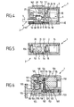
- FIG. 6 Another embodiment of the locking / unlocking device 1 according to the invention, illustrated in FIG. 6, can also, among others, be envisaged.
- the first blade 118 is in one piece. It is attracted to said electromagnet 115 by means of a rod, not shown, sliding in the core of said electromagnet 115.
- said first blade 118 is provided, for example, with an orifice through which said rod is capable of opening, a protuberance being provided at the end of said rod so as to entrain said first blade 118 towards the electri - magnet 115.
- the device according to the invention comprises means 160 to allow locking without power to the coil.
- the spring of said piston 152 is, in particular, provided compressed when the device 1 is in the locked position and able to relax, thus allowing the said first blade 118 to be kept in the unlocked position thanks, for example, to a ring 161 secured to said piston 152 under said first blade 118.
- Said piston 152 is possibly provided in the axis of the movable member 103 and then facilitates unlocking. In fact, said piston, when it relaxes, thus acts on said mobile member 3.
- said piston 152 facilitates the breaking of the bracing between said first blade 118 and said pressure blade 120 and thus authorizes the use of a lower power electromagnet.
- said movable member 103 has at its end a protrusion 155, substantially of the dimensions of said housing 104, extending a rod 156 of reduced size. Such an arrangement facilitates the introduction of said movable member 103 into said housing 104.
- said blocking means 6; 106 are integrated, for example, in a housing 32; 132 formed by said fixed member 2; 102.
- Said housing 32; 132 thus contains, in particular, the electromagnet 15; 115, the blades 18; 118, 20; 120 as well as their axis of articulation 21; 121, 22; 122 and / or the first and second springs 19; 119, 29; 129.
- the reduction in the size of the locking device 1, according to the invention, is thus favored.
- said housing 32; 132 is in particular provided with a removable cover, for example transparent.
- the walls of said housing 32; 132 have, in particular, one or more orifices 33 allowing, for example, the fixing of said housing 32; 132 on its support, such as the tubular frame 7; 107 and / or the fixing, in its internal cavity, of the various elements of the locking means 6; 106.
- Said housing 4; 104 has, for example, the shape of a groove inside which said projection 5; 105 has a transverse opening.
- emergency unlocking means may possibly be provided in the event of a malfunction of the electromagnetic locking means 6. They consist, for example, of a metal rod intended to be introduced by percussion with the inside the housing 32 to unlock the bracing, an imprint on the external surface of said housing 32 can be provided, in particular to facilitate the guiding of said metal rod.
- the present invention also relates to a lock allowing the control by an electric current of a lock or locking / unlocking device such as, in particular, that described above, equipping, in particular removable wall supports, cabinet doors, gates candelables or others.
- said lock may be used, in general, in all sectors of economic activity in which it is necessary to use locks controlled by an electric current.
- the lock according to the invention comprises at least one barrel 201; 301 and a key 202; 302 able to cooperate so as to allow control by an electric current of a lock.
- said barrel 201; 301 and said key 202; 302 are each provided with at least two connection terminals 243; 304, 244; 305, 241; 306, 242; 307, one being connectable to ground, said connection terminals 241; 306, 242; 307 of key 202; 302 being able to be brought into contact with the connection strips 243; 304, 244; 305 of barrel 201; 301.
- said lock comprises an energy source 208, 308 capable of supplying the connection strips of the key 2; 302 or barrel 201; 301 as well as coding means 209; 309 for controlling the lock, said coding relating to bringing said connection terminals 243 into contact; 304, 244; 305, 241; 306, 242; 307 which is only possible in the event of nesting in the barrel 201; 301 of key 202; 302 corresponding to him.
- connection terminals consist, in particular, of flexible blades, capable of establishing contact by deformation one against the other and / or by plugs cooperating with orifices, each provided on the barrel 201; 301 or on the key 202; 302, or vice versa.
- said energy source 208, 308 is provided in the key 202; 302, for example at the level of its gripping zone 210. It consists, for example, of a battery 211, 311.
- said key 202 thus comprises, for example, an electric battery 237, capable of constituting the source of electricity supply necessary here for actuation of the locking / unlocking device 1.
- the fact of providing said battery 237 in said key 202 makes it possible to place the energy source authorizing unlocking at exterior of the installation on which said device 1 according to the invention is fixed and reinforces security.
- said key 202 is provided, for example, with a rod 238 comprising two electrical plugs 239, 240, connected at one end to the terminals of said battery 237, and having, at their opposite end, said two terminals 241, 242, arranged so as to be able to come into contact with said two terminals 243, 244, of given spacing, provided inside said lock 201.
- the spacing that it will therefore be necessary to confer on said terminals 241, 242, provided at the end of said rod 238 in order to actuate said device 1, thus reinforces the reliability of the locking and constitutes coding means 209.
- the housing 32; 132 of the device 1 and said lock can be separated and provided at two different levels in the installations which are equipped with it.
- said lock and said electromagnet 15; 115 are connected, in particular, as mentioned above, by electric cables 45.
- Such a solution also makes it possible to reinforce the reliability of the locking offered by the device according to the invention.
- said socket 301 and said key 302 have, optionally, a longitudinal axis 312 of symmetry.
- Said barrel 301 consists, in particular, of a sleeve 313 and a protuberance 314, provided inside said sleeve 313, said sleeve 313 and said protuberance 314 defining between them a gap 315, by annular example, opening on the side opposite the bottom of said socket 313.
- said lock does not consist of a stator and a rotor movable relative to each other. It therefore has a less complex structure and its implementation is simplified.
- Said key 302 comprises at least, in particular a barrel 316, having a tubular structure, capable of being fitted into said interstice 315.
- Said protuberance 314 is, in particular, made up of a cylinder, the cavity of the sleeve 313 inside which it is provided, being itself, for example, cylindrical. Said protuberance 314 and said cavity are, optionally, coaxial and / or of substantially circular section.
- said barrel 316 has a tubular structure, also possibly cylindrical, in particular of substantially circular section, its thickness being less than that of the gap 315.
- said protuberance 314 may also be hollow, the barrel 316 of the key 302 then having, in correspondence, projections in its own cavity 317.
- connection terminals 304, 305, 306, 307 are provided, in particular, on said barrel 316 and / or in said interstice 315, for example in said cavity 317 and on said protuberance 314.
- Said coding means 309 are constituted, for example, by the relative positioning of the connection terminals 304, 305, 306, 307 on the key 302 and on the socket 301.
- keying pins can also be provided opposite on said key 302 and said lock 301 to indicate the direction of interlocking.
- Said coding means 309 can also be constituted, for example, by the relative dimensions of the barrel 316 and the gap 315, in particular their thickness and / or their depth.
- said coding means 309 can also, for example, consist of cutouts 319, provided on said barrel 316, and extra thicknesses of material 320 provided in correspondence in said interstice 315, or vice versa.
- Said cutouts are constituted, in particular, by slots 319, provided at the end of the barrel 316 and oriented parallel to the longitudinal axis 312, while said extra thicknesses of material are constituted by rods 320, provided at the bottom of said interstice 315 and oriented parallel to the longitudinal axis 312, the dimensions of said cutouts 319 and said rods 320 corresponding to each other, in particular as regards their length.
- said cutouts 319 are provided, in particular, in the thickness of the barrel 316.
- the lock according to the invention may possibly be provided at the level of the barrel 201; 301 and / or the key 202; 302 of a spring element, capable of expelling at least partially, said key 202; 302 of said barrel 201; 301 so as to prevent the electrical connection from lasting too long and running the risk of unnecessarily discharging the energy source.
- the lock controlled by the lock described above may also be constituted, for example, according to embodiments not illustrated, by an electric or electronic component playing the role, in particular, of switch in an electric or electronic circuit .
- Said component is connected, in particular, to the terminals of the barrel.
Landscapes
- Engineering & Computer Science (AREA)
- Structural Engineering (AREA)
- Physics & Mathematics (AREA)
- Electromagnetism (AREA)
- Lock And Its Accessories (AREA)
Applications Claiming Priority (2)
| Application Number | Priority Date | Filing Date | Title |
|---|---|---|---|
| FR9607244A FR2749606B1 (fr) | 1996-06-06 | 1996-06-06 | Dispositif de verrouillage du mouvement relatif de deux organes l'un par rapport a l'autre, notamment destine a des supports de parois amovibles, des portes de coffrets, des portillons de candelabres ou autres |
| FR9607244 | 1996-06-06 |
Publications (1)
| Publication Number | Publication Date |
|---|---|
| EP0811738A1 true EP0811738A1 (de) | 1997-12-10 |
Family
ID=9492945
Family Applications (1)
| Application Number | Title | Priority Date | Filing Date |
|---|---|---|---|
| EP97490017A Withdrawn EP0811738A1 (de) | 1996-06-06 | 1997-06-06 | Verriegelungsvorrichtung |
Country Status (2)
| Country | Link |
|---|---|
| EP (1) | EP0811738A1 (de) |
| FR (1) | FR2749606B1 (de) |
Cited By (10)
| Publication number | Priority date | Publication date | Assignee | Title |
|---|---|---|---|---|
| DE19801752C1 (de) * | 1998-01-20 | 1999-05-12 | Dorma Gmbh & Co Kg | Verriegelungseinrichtung für Notausgangstüren |
| WO2007034474A1 (en) * | 2005-09-19 | 2007-03-29 | Meteoronics Ltd | Electric locks with release hammer |
| WO2011023187A3 (de) * | 2009-08-27 | 2011-05-19 | Tap Ltd. | Schloss |
| US20140338408A1 (en) * | 2013-05-14 | 2014-11-20 | Asustek Computer Inc. | Electronic system with locking function by electronically controlled |
| US20150021926A1 (en) * | 2013-07-19 | 2015-01-22 | Amsafe Commercial Products, Inc. | Latch device and anchor with swivel coupling |
| FR3036421A1 (fr) * | 2015-05-20 | 2016-11-25 | Kendrion Kuhnke Automation Gmbh | Dispositif de verrouillage d'un doigt de retenue relie a un couvercle |
| US20170254119A1 (en) * | 2016-03-03 | 2017-09-07 | Dan Raz Ltd. | Latch arrangement having a stop latch |
| US10480213B2 (en) | 2015-11-29 | 2019-11-19 | Dan Raz Ltd. | Door or other closable panel with lock-actuating linkage |
| US10822837B2 (en) | 2017-09-03 | 2020-11-03 | Dan Raz Ltd. | Obliquely-engaging locking mechanism |
| US10865588B2 (en) | 2015-08-24 | 2020-12-15 | Dan Raz Ltd. | Securing mechanism for a sliding panel |
Citations (6)
| Publication number | Priority date | Publication date | Assignee | Title |
|---|---|---|---|---|
| FR15078E (fr) * | 1909-07-16 | 1912-04-20 | Gustave Sahmer | Dispositif électrique de verrouillage et de déverrouillage pour serrures à pene dormant |
| DE284194C (de) * | 1914-02-13 | 1915-05-14 | Beckmann Albert | Schlosssicherung mit einer in den riegel eingreifenden, auf elektrischem wege auslösbaren sperrklinke |
| DE386544C (de) * | 1921-06-19 | 1923-12-11 | Hugo Klostermann | Elektromagnetische Tuersicherung |
| DE433321C (de) * | 1923-08-31 | 1926-09-01 | Internationales Handelsbuero F | Elektrische Schlosssicherung |
| EP0096400A2 (de) * | 1982-06-07 | 1983-12-21 | ELEKTRONIKBAU Krippner & Kletzmaier Gesellschaft m.b.H. & Co. | Schlossanlage zur Sicherung von Türen |
| FR2624904A1 (fr) * | 1987-12-16 | 1989-06-23 | Vesnitch Yves | Verrou simplifie pour fermeture coulissante ou pivotante avec securite incendie |
-
1996
- 1996-06-06 FR FR9607244A patent/FR2749606B1/fr not_active Expired - Fee Related
-
1997
- 1997-06-06 EP EP97490017A patent/EP0811738A1/de not_active Withdrawn
Patent Citations (6)
| Publication number | Priority date | Publication date | Assignee | Title |
|---|---|---|---|---|
| FR15078E (fr) * | 1909-07-16 | 1912-04-20 | Gustave Sahmer | Dispositif électrique de verrouillage et de déverrouillage pour serrures à pene dormant |
| DE284194C (de) * | 1914-02-13 | 1915-05-14 | Beckmann Albert | Schlosssicherung mit einer in den riegel eingreifenden, auf elektrischem wege auslösbaren sperrklinke |
| DE386544C (de) * | 1921-06-19 | 1923-12-11 | Hugo Klostermann | Elektromagnetische Tuersicherung |
| DE433321C (de) * | 1923-08-31 | 1926-09-01 | Internationales Handelsbuero F | Elektrische Schlosssicherung |
| EP0096400A2 (de) * | 1982-06-07 | 1983-12-21 | ELEKTRONIKBAU Krippner & Kletzmaier Gesellschaft m.b.H. & Co. | Schlossanlage zur Sicherung von Türen |
| FR2624904A1 (fr) * | 1987-12-16 | 1989-06-23 | Vesnitch Yves | Verrou simplifie pour fermeture coulissante ou pivotante avec securite incendie |
Cited By (16)
| Publication number | Priority date | Publication date | Assignee | Title |
|---|---|---|---|---|
| DE19801752C1 (de) * | 1998-01-20 | 1999-05-12 | Dorma Gmbh & Co Kg | Verriegelungseinrichtung für Notausgangstüren |
| WO2007034474A1 (en) * | 2005-09-19 | 2007-03-29 | Meteoronics Ltd | Electric locks with release hammer |
| WO2011023187A3 (de) * | 2009-08-27 | 2011-05-19 | Tap Ltd. | Schloss |
| US10301845B2 (en) * | 2013-05-14 | 2019-05-28 | Asustek Computer Inc. | Electronic system with locking function by electronically controlled |
| US20140338408A1 (en) * | 2013-05-14 | 2014-11-20 | Asustek Computer Inc. | Electronic system with locking function by electronically controlled |
| US20150021926A1 (en) * | 2013-07-19 | 2015-01-22 | Amsafe Commercial Products, Inc. | Latch device and anchor with swivel coupling |
| US9718427B2 (en) * | 2013-07-19 | 2017-08-01 | Shield Restraint Sytems, Inc. | Latch device and anchor with swivel coupling |
| FR3036421A1 (fr) * | 2015-05-20 | 2016-11-25 | Kendrion Kuhnke Automation Gmbh | Dispositif de verrouillage d'un doigt de retenue relie a un couvercle |
| US10865588B2 (en) | 2015-08-24 | 2020-12-15 | Dan Raz Ltd. | Securing mechanism for a sliding panel |
| US10480213B2 (en) | 2015-11-29 | 2019-11-19 | Dan Raz Ltd. | Door or other closable panel with lock-actuating linkage |
| US20170254119A1 (en) * | 2016-03-03 | 2017-09-07 | Dan Raz Ltd. | Latch arrangement having a stop latch |
| US10487545B2 (en) * | 2016-03-03 | 2019-11-26 | Dan Raz Ltd. | Latch arrangement having a stop latch |
| US11359412B2 (en) | 2016-03-03 | 2022-06-14 | Dan Raz Ltd. | Latch arrangement having a stop latch |
| US11371263B2 (en) | 2016-03-03 | 2022-06-28 | Dan Raz Ltd. | Latch arrangement having a stop latch |
| US10822837B2 (en) | 2017-09-03 | 2020-11-03 | Dan Raz Ltd. | Obliquely-engaging locking mechanism |
| US11598125B2 (en) | 2017-09-03 | 2023-03-07 | Dan Raz Ltd. | Latch arrangement |
Also Published As
| Publication number | Publication date |
|---|---|
| FR2749606B1 (fr) | 1999-07-23 |
| FR2749606A1 (fr) | 1997-12-12 |
Similar Documents
| Publication | Publication Date | Title |
|---|---|---|
| EP3477023B1 (de) | Schloss und schlüssel für dieses schloss | |
| EP2412901B1 (de) | Elektronisches Schloss | |
| EP3431684A1 (de) | Elektronisches schloss | |
| EP0811738A1 (de) | Verriegelungsvorrichtung | |
| EP1732174A1 (de) | Steckdose mit beweglichem Schachtboden und versenkbarer Abdeckplatte | |
| EP2248971B1 (de) | Elektronisches Schloss | |
| FR2761396A1 (fr) | Serrure a commande electronique | |
| EP3477026B1 (de) | Elektronischer schlüssel für ein elektronisches schloss | |
| FR2511069A1 (fr) | Barre antipanique avec dispositif de blocage electrique | |
| CA1258382A (fr) | Dispositif de securite pour la fermeture et l'ouverture de portes, fenetres et similaires | |
| EP3477027B1 (de) | Einheit aus einem elektronischen schloss und einem elektronischen schlüssel | |
| EP2148027A1 (de) | Elektromechanische Verriegelungsvorrichtung | |
| EP3844358A1 (de) | Mechanismus zum verriegeln eines flügels gegen einen rahmen | |
| EP2071105A1 (de) | Schlüssel mit versenkbarem Einsatz | |
| EP1040243B1 (de) | Elektrische steuerungsvorrichtung zur entriegelung einer drehenden welle, insbesondere eines schlosses und schloss mit solcher vorrichtung | |
| EP1854942A1 (de) | Vorrichtung zur Zugangsbeschränkung zum Schloss eines Verriegelungsmechanismus, insbesondere einer Drehsperre | |
| FR3001751A1 (fr) | Serrure electronique | |
| WO2022053746A1 (fr) | Système de fermeture compose d une serrure a goupilles avec verrou tournant servant d interrupteur a une ou plusieurs serrrures electriques et cette ou ces serrures electriques | |
| EP1538286B1 (de) | Schliesszylinder | |
| EP1672746B1 (de) | Steckdose ausgerüstet mit zusätzlichem Sicherungsmittel | |
| FR3134593A1 (fr) | Boîtier comprenant une porte et muni de deux dispositifs de verrouillage | |
| FR3143222A1 (fr) | Système multi contacts électriques avec clef à zones isolantes | |
| FR3081483A1 (fr) | Ensemble de serrure automatique | |
| FR2766225A1 (fr) | Dispositif d'ouverture/fermeture des ouvrants d'un vehicule automobile | |
| FR3052473A3 (fr) | Structure de serrure electrique a pene piston |
Legal Events
| Date | Code | Title | Description |
|---|---|---|---|
| PUAI | Public reference made under article 153(3) epc to a published international application that has entered the european phase |
Free format text: ORIGINAL CODE: 0009012 |
|
| AK | Designated contracting states |
Kind code of ref document: A1 Designated state(s): BE CH DE ES FR GB IT LI |
|
| 17P | Request for examination filed |
Effective date: 19971027 |
|
| AKX | Designation fees paid |
Free format text: BE CH DE ES FR GB IT LI |
|
| RBV | Designated contracting states (corrected) |
Designated state(s): BE CH DE ES FR GB IT LI |
|
| 17Q | First examination report despatched |
Effective date: 19990702 |
|
| GRAP | Despatch of communication of intention to grant a patent |
Free format text: ORIGINAL CODE: EPIDOSNIGR1 |
|
| STAA | Information on the status of an ep patent application or granted ep patent |
Free format text: STATUS: THE APPLICATION IS DEEMED TO BE WITHDRAWN |
|
| 18D | Application deemed to be withdrawn |
Effective date: 20060308 |