EP1537926A1 - Verfahren zur Herstellung eines gegossenen Metallstranges hoher Reinheit - Google Patents
Verfahren zur Herstellung eines gegossenen Metallstranges hoher Reinheit Download PDFInfo
- Publication number
- EP1537926A1 EP1537926A1 EP04105685A EP04105685A EP1537926A1 EP 1537926 A1 EP1537926 A1 EP 1537926A1 EP 04105685 A EP04105685 A EP 04105685A EP 04105685 A EP04105685 A EP 04105685A EP 1537926 A1 EP1537926 A1 EP 1537926A1
- Authority
- EP
- European Patent Office
- Prior art keywords
- molten metal
- distribution vessel
- covering
- supply
- vessel
- Prior art date
- Legal status (The legal status is an assumption and is not a legal conclusion. Google has not performed a legal analysis and makes no representation as to the accuracy of the status listed.)
- Granted
Links
Images


Classifications
-
- B—PERFORMING OPERATIONS; TRANSPORTING
- B22—CASTING; POWDER METALLURGY
- B22D—CASTING OF METALS; CASTING OF OTHER SUBSTANCES BY THE SAME PROCESSES OR DEVICES
- B22D39/00—Equipment for supplying molten metal in rations
-
- B—PERFORMING OPERATIONS; TRANSPORTING
- B22—CASTING; POWDER METALLURGY
- B22D—CASTING OF METALS; CASTING OF OTHER SUBSTANCES BY THE SAME PROCESSES OR DEVICES
- B22D11/00—Continuous casting of metals, i.e. casting in indefinite lengths
- B22D11/10—Supplying or treating molten metal
- B22D11/11—Treating the molten metal
- B22D11/111—Treating the molten metal by using protecting powders
-
- B—PERFORMING OPERATIONS; TRANSPORTING
- B22—CASTING; POWDER METALLURGY
- B22D—CASTING OF METALS; CASTING OF OTHER SUBSTANCES BY THE SAME PROCESSES OR DEVICES
- B22D11/00—Continuous casting of metals, i.e. casting in indefinite lengths
- B22D11/16—Controlling or regulating processes or operations
-
- B—PERFORMING OPERATIONS; TRANSPORTING
- B22—CASTING; POWDER METALLURGY
- B22D—CASTING OF METALS; CASTING OF OTHER SUBSTANCES BY THE SAME PROCESSES OR DEVICES
- B22D37/00—Controlling or regulating the pouring of molten metal from a casting melt-holding vessel
-
- B—PERFORMING OPERATIONS; TRANSPORTING
- B22—CASTING; POWDER METALLURGY
- B22D—CASTING OF METALS; CASTING OF OTHER SUBSTANCES BY THE SAME PROCESSES OR DEVICES
- B22D39/00—Equipment for supplying molten metal in rations
- B22D39/02—Equipment for supplying molten metal in rations having means for controlling the amount of molten metal by volume
Definitions
- the invention relates to a method for producing a cast metal strand higher Purity from a molten metal, preferably a molten steel, wherein the Molten metal melt fed from a melt container is fed to a distribution vessel and regulated by this distribution vessel is discharged into a continuous casting mold and wherein the Metal melt at least in the distribution vessel during the stationary casting operation with Covering a cover is covered.
- the invention relates to a starting method for a continuous casting plant for Production of a cast high-purity metal strand from a molten metal, in particular a molten steel.
- the continuous casting plant can with a mold arbitrary Be equipped.
- the cross-sectional format of the metal strand to be cast can be arbitrary.
- special Requirements for the start phase of the casting process already after the first few meters Cast tape to be able to produce a tape, which high quality standards equivalent.
- the invention particularly, but not exclusively, relates to Strip casting with a two-roll caster after the vertical two-roll casting process.
- Continuous casting is usually the liquid metal from a ladle over at least one intermediate vessel or distributor vessel fed to a cooled mold, in the solidification process of the molten metal to a metal strand at least initiated becomes.
- the transfer of the molten metal from the ladle into the distribution vessel takes place predominantly through shadow tubes and from the distributor into the mold through dip tubes, the in the stationary casting operation in the melt pool of the respective downstream vessel immerse and so a calm and steady flow and forwarding as possible allow the molten metal into the mold.
- the intermediate vessel and optionally in the mold accumulated molten metal of covered by a layer of slag, through which the metal bath surface is protected from oxidation becomes.
- the more intensive the metal bath movement takes place in the individual melting vessels The more slag particles are covered by the molten metal Slag layer entered into the metal bath and the more particles of the Refractory material from the lining of the melting vessels are caused by erosion also fed to the metal bath.
- the deposition of foreign particles from the molten metal to the metal bath surface or into the slag layer through hampered intensive metal bath movement.
- the quality of the cast strand is reduced when Strong bath level fluctuations occur as they are in the startup phase of the casting process at the first filling of the distribution vessel are unavoidable, or as they during the Performing the pan change in sequence casting occur in the usual the changeover time of the ladle is bridged with the molten metal in the distributor and therefore is poured with continuously decreasing manifold bath level height.
- the Stability of the melt flow in the distribution vessel is thereby greatly impaired and the Molten metal is exposed to undesirable slag entry.
- the object of the invention is therefore these disadvantages and difficulties of the known To avoid prior art and a method of the type described above to propose, with the already directly at the beginning of the quasi-stationary casting phases a metal strand of high purity can be poured, at which the starting phase of the Casting process can be kept as short as possible and at least impact decay as quickly as possible from non-stationary casting phases.
- the term "distribution vessel” is here not only on the receptacle for molten metal limited by which the transfer or distribution of molten metal in a Mold is possible, thus a mold is arranged directly in front, but can all Include melt vessels between the ladle and the mold, in which the Molten metal can be covered with a covering.
- the at least approximately stationary Angussbadspiegel way reach and thus the time span expresses turbulent and uncontrolled bath movement in Passing through the distribution vessel quickly, it is appropriate that until reaching the At least approximately stationary Angussbadaptiere basically molten metal in the Supplied to the distribution vessel, but no molten metal removed from the distribution vessel becomes.
- the equivalent filling weight can also be used the molten metal in the distribution vessel can be used as the determining parameter for example, for the supply amount of molten metal with maximum filling rate.
- the reduced fill rate does not represent a constant value over the remaining fill time, but follows a continuously or gradually decreasing time course, whereby the Continuously calm flow conditions in the distribution vessel.
- the period of interruption of the melt supply is between 8 sec and 10 min, preferably between 60 and 270 sec.
- Covering agents usually consist of a covering powder and form a slag layer.
- a favorable time for the task of a covering agent is given, if within a time period which is the time of reaching the at least approximately stationary Angussbadaptaptproof Escape is upstream, set the lowest possible filling rate and is kept constant and within this period, especially in the second Half, the masking agent is applied to the melt bath.
- a further expedient possibility for the task of a covering agent is given, when first covering the free bath surface with a cover agent within the period of interruption of the supply of melt begins. This will be the Covering applied only at a time when already a substantial Calming of the bathroom mirror has occurred.
- an application of the Abdeckstoffs at maximum fill rate to a significant entry of foreign particles in the melt bath and an inhomogeneous distribution of the covering on the Melt bath lead, as the velocities of the liquid phase at the bath level quite 5 to 10 times higher than in the largely stationary mode of operation.
- the Intensity of surface turbulence increases with the square of the Surface speed.
- the flooding of the Abdeckstoffs favors in the metal bath.
- a Covering agent begins the first time covering the free bath surface with a Covering agent in a period of time from 30 seconds, preferably from 8 seconds before the Resumption of the supply of melt after the interruption of the supply of melt.
- a further advantageous embodiment results when the covering of the free Bath surface with a covering only after casting the continuous casting mold starts.
- the shade tube surrounding area of the free bath surface in the distribution vessel from a cover with a covering means is shielded.
- the amount of the molten metal supplied to the distribution vessel and the amount of the metal melt discharged from the distributor vessel amounts to when casting a steel strip, with a casting thickness of 1.0 - 5.0 mm and a casting width of 1.0 m to 2.0 m in the largely stationary casting operation between 0.5 t / min and 4.0 t / min, preferably between 0.8 t / min and 2.0 t / min.
- This information refers to the use of a Two-roll casting machine with the desired cast product and corresponding Interpretation.
- a case by case manual task of the cover means requires sufficient Accessibility of the distribution vessel for the operator and also brings the Disadvantage of additional slag inclusions due to the sudden local task of a larger amount of the covering with it.
- the covering is therefore in fine-grained Mold or powder, preferably with a semi or fully automatic Feeding device, applied.
- the interior of the distribution vessel is by a distributor cover against the free Atmosphere shielded, whereby it is expedient if during or before the Clearatmosphere an inerting of the distribution vessel takes place to the reactive oxygen in Interior of the distribution vessel largely eliminate.
- the adjustment and monitoring of Millg billador altar sit preferably takes place via a distributor weight measurement or with an equivalent measuring method for Level measurement.
- the Railg dirtytage Ousts, or at least approximately Stationary sprue mirror height can be measured using other direct or indirect measuring methods are also determined, e.g. with floats, optical observation of the BadLiteober Structure, sound level measurement, eddy current measurement and similar Measurement methods.
- the distribution vessel When restarting the casting plant, the distribution vessel is free at the beginning of Clearitzphase of molten metal and expediently also free of covering agents or slags, and Refractory residues.
- Fig. 1 shows a schematic representation of a Zweiwalzeng tellmaschine as a Possibility to carry out the process according to the invention with the essential structural components for feeding the molten metal in the opposite direction of two rotating casting rolls 1, 2 and pressed against the end faces of the casting rolls Side plates 3 formed continuous casting mold 4.
- the molten metal is from a Melt container 5, which is usually a replaceable on fork arms 6 of a Ladle turret supported ladle is formed by a shade tube 7 in a Manifold 8 passed over.
- the shade tube 7 is a slide closure 9 as Control element for the flow rate assigned.
- From the distribution vessel 8 flows Molten metal volume controlled by a Tauchgit beaumaschine 10 in the mold cavity 11 of Continuous casting mold 4.
- the immersion casting tube 10 is also a slide closure 12 for Control associated with the continuous casting mold 4 to be supplied amount of melt.
- the Closure organs can also be formed by plugs that, from above through the Melting bath projecting, the outflow opening of the respective melt container adjustable close.
- the amount of molten metal stored in the distribution vessel 8 during the stationary casting kept as constant as possible. This is achieved by that in the distribution vessel a predetermined G stealaptproof way h of the molten metal is adjusted and this G stealapt yet is largely maintained by an inflow control. A largely constant G stealaptains ensures a uniform Melt transfer into the continuous casting mold 4.
- the continuous casting mold prepared for the casting start wherein the casting gap between the casting rolls by a Anfahrstrang is closed or appropriate precautions for a casting start be taken without startup.
- Such a start-up method without use a Anfahrstranges is for example in the previously unpublished Austrian Patent Application A 1367/2002 described.
- a melt container filled with molten metal is introduced into its pouring position above the distributor vessel.
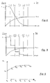
- the filling process of the distribution vessel takes place in a possible embodiment variant according to the filling curve course shown in FIG.
- the molten metal is introduced in the first filling phase (time t 0 -t 1 ) with the greatest possible opening of the slide closure in the distribution vessel, ie the molten metal enters the distribution vessel with approximately maximum filling rate m ⁇ fill, max , the slide closure closed on the output side of the distribution vessel is held.
- FIG. 3 shows a further embodiment variant of a possible filling curve progression, wherein the filling rate m ⁇ fill is gradually decreased in several stages after reaching about 40% of the at least approximately stationary sprue level at the time t 1 , the reduction of the filling rate in the individual times t 1 to t 5 is carried out so that a degressive approximation of the level of the bath level h pool to the AngussbadLite forgotten h pool, op takes place.
- Fig. 4 shows the increase of the distributor weight m v over the filling time, starting from the empty weight m 0 of the distributor vessel to the distributor weight m 5 , which is achieved upon reaching the at least approximately stationary Angussbadaptaptiere Little h pool, op .
- the distribution vessel 8 is covered with a distributor cover 16, with which the Interior of the distribution vessel is shielded from the atmosphere ( Figure 1). This also gives the possibility, even before the supply of molten metal To perform inerting of the interior.
- Substantially coinciding with the resumption of the supply of melt into the Distribution vessel begins the introduction of the molten metal in the continuous casting mold, or their filling and the initiation of the continuous casting operation.
- the Amount of the molten metal supplied to the distribution vessel as a function of the in the Continuous casting mold introduced melt quantity set.
- An operating bath level for the stationary casting operation may well differ from the Angussbadspiegel Little and is set in the first phase of the stationary casting operation or as needed.
- Deviations of the BadLite altar of the desired at least approximately stationary sprue bath level or operating bath level height are over one Distributor weight measurement detected.
- the distribution vessel 8 is this via measuring cells 17 on a support frame 18, for example a movable Distribution trolley, supported.
- FIG. 5 shows in analogy to FIG. 2 the filling process of the distribution vessel on the basis of the filling rate m ⁇ v and the level of the bath level h pool in a time-dependent course.
- the molten metal is introduced in a filling phase t 0 to t 1 at the maximum opening of the slide valve closure on the melt vessel in the manifold and the filling process then continued with decaying filling rate in the period t 1 to t 4 .
- op which extends in the time interval t 4 to t 5 , the supply of melt takes place at a filling rate which is substantially reduced compared with the maximum filling rate but largely kept constant.
- the task of covering means P on the melt bath in the distribution vessel begins. From the time t 5 of the casting operation begins with the filling of the continuous casting mold, wherein the filling rate of the mold m ⁇ m has a time course, as shown for example in Fig. 5 in the bottom diagram. At the same time, the filling rate in the distribution vessel m ⁇ v is adjusted to an operating bath level h pool, op .
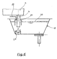
- Fig. 6 shows a possibility that the entry of the melt bath applied covering in the interior of the melt bath in the outer wall the shadow tube 7 should largely rule out.
- accumulated molten metal flows through the vertical immersed in the melt Shade tube 7 more molten metal from the melt container 5 to continuously.
- the inflowing molten metal creates a suction effect along the shadow tube 7 and pulls any slag / covering material collected in this area downwards the molten metal.
- a cover 21 which is cup-shaped, which is the Shadow tube at a radial distance to this surrounds and from above into the molten metal protrudes, the formed slag layer 20 from the critical area near the shade tube kept away.
- This upwardly closed cover 21 can over the Inert gas line 22 are rendered inert if necessary.
- the shade tube 7 is located in Outflow of the molten metal only a hint illustrated flow-damping element 23 (turbo-stop) firmly anchored in the distribution vessel, whereby the inflowing metal beam is strongly braked and diverted targeted.
- the starting method described has been particularly successful in connection with a distributor vessel, which is described in WO 03/051560 and a Geometry, the deposition of extraneous particles especially promotes.
Landscapes
- Engineering & Computer Science (AREA)
- Mechanical Engineering (AREA)
- Continuous Casting (AREA)
Abstract
Description
- Fig. 1
- eine schematische Darstellung einer Zweiwalzengießanlage mit einem Schmelzenbehälter und einem Verteilergefäß zur Durchführung des erfindungsgemäßen Verfahrens,
- Fig. 2
- den Verlauf einer Anfahrkurve für das Füllen des Verteilergefäßes (Füllrate) nach dem erfindungsgemäßen Verfahren in einer ersten Ausführungsform,
- Fig. 3
- den Verlauf einer Anfahrkurve für das Füllen des Verteilergefäßes (Füllrate) nach dem erfindungsgemäßen Verfahren in einer zweiten Ausführungsform,
- Fig. 4
- den zeitlichen Verlauf des Verteilergewichtes während des Füllens des Verteilergefäßes,
- Fig. 5
- den Verlauf von Anfahrkurven für das Füllen des Verteilergefäßes und der Stranggießkokille nach einer dritten Ausführungsform,
- Fig. 6
- ein Schattenrohr mit einer mechanischen Abschirmung gegen Kontakt mit Schlacke.
Claims (20)
- Verfahren zur Herstellung eines gegossenen Metallstranges hoher Reinheit aus einer Metallschmelze, vorzugsweise einer Stahlschmelze, wobei die Metallschmelze von einem Schmelzenbehälter (5) geregelt einem Verteilergefäß (8) zugeführt und von diesem Verteilergefäß geregelt in eine Stranggießkokille (4) abgeführt wird und wobei die Metallschmelze zumindest im Verteilergefäß während des stationären Gießbetriebes mit einem Abdeckmittel bedeckt ist, dadurch gekennzeichnet, dass die sich in einer Erstfüllphase im Verteilergefäß ausbildende freie Badoberfläche der Metallschmelze nach Erreichen einer vorbestimmten wenigstens annähernd stationären Angussbadspiegelhöhe (h pool,op) zumindest teilweise mit einem Abdeckmittel bedeckt wird.
- Verfahren nach Anspruch 1, dadurch gekennzeichnet, dass bis zum Erreichen der wenigstens annähernd stationären Angussbadspiegelhöhe Metallschmelze in das Verteilergefäß zugeführt, jedoch keine Metallschmelze aus dem Verteilergefäß abgeführt wird.
- Verfahren nach einem der vorhergehenden Ansprüche, dadurch gekennzeichnet, dass die Zufuhr der Metallschmelze in das Verteilergefäß bis zum Erreichen einer Badspiegelhöhe von 5% bis 50%, vorzugsweise von 10% bis 30%, der wenigstens annähernd stationären Angussbadspiegelhöhe mit annähernd maximaler Füllrate (m ˙ fill,max ) erfolgt und die Zufuhr der Metallschmelze in das Verteilergefäß anschließend bis zum Erreichen der wenigstens annähernd stationären Angussbadspiegelhöhe mit gegenüber der annähernd maximalen Füllrate reduzierten Füllrate erfolgt.
- Verfahren nach Anspruch 3, dadurch gekennzeichnet, dass die reduzierte Füllrate einem kontinuierlich oder schrittweise abnehmenden zeitlichen Verlauf folgt.
- Verfahren nach einem der Ansprüche 1 oder 2, dadurch gekennzeichnet, dass die Zufuhr der Metallschmelze in das Verteilergefäß bis zum Eintauchen des Schattenrohres in die in das Verteilergefäß eingebrachte Metallschmelze mit maximaler Füllrate erfolgt und die Zufuhr der Metallschmelze in das Verteilergefäß anschließend bis zum Erreichen der wenigstens annähernd stationären Angussbadspiegelhöhe mit einer gegenüber der annähernd maximalen Füllrate reduzierten Füllrate erfolgt.
- Verfahren nach einem der Ansprüche 3 bis 5, dadurch gekennzeichnet, dass innerhalb einer Zeitspanne, die dem Zeitpunkt des Erreichens der wenigstens annähernd stationären Angussbadspiegelhöhe vorgelagert ist, eine möglichst geringe Füllrate eingestellt und weitgehend konstant gehalten wird und innerhalb dieser Zeitspanne, insbesondere in deren zweiten Hälfte, das Abdeckmittel auf das Schmelzenbad aufgegeben wird.
- Verfahren nach einem der Ansprüche 1 bis 5, dadurch gekennzeichnet, dass die Zufuhr von Metallschmelze in das Verteilergefäß mit Erreichen der wenigstens annähernd stationären Angussbadspiegelhöhe für eine Zeitspanne unterbrochen wird.
- Verfahren nach Anspruch 7, dadurch gekennzeichnet, dass die Zeitspanne der Unterbrechung der Schmelzenzufuhr zwischen 8 sec und 10 min, vorzugsweise zwischen 60 und 270 sec beträgt.
- Verfahren nach einem der vorhergehenden Ansprüche, dadurch gekennzeichnet, dass das erstmalige Abdecken der freien Badoberfläche mit einem Abdeckmittel innerhalb der Zeitspanne der Unterbrechung der Schmelzenzufuhr beginnt.
- Verfahren nach einem der Ansprüche 1 bis 7, dadurch gekennzeichnet, dass das erstmalige Abdecken der freien Badoberfläche mit einem Abdeckmittel in einer Zeitspanne ab 30 sec, vorzugsweise ab 8 sec, vor der Wiederaufnahme der Schmelzenzufuhr nach der Unterbrechung der Schmelzenzufuhr beginnt.
- Verfahren nach einem der vorhergehenden Ansprüche 1 bis 7, dadurch gekennzeichnet, dass das Abdecken der freien Badoberfläche mit einem Abdeckmittel frühestens in einer Zeitspanne vor dem Beginn der Abführung von Metallschmelze aus dem Verteilergefäß beginnt, die vorzugsweise höchstens der Hälfte der Zeitspanne der Unterbrechung der Zufuhr von Metallschmelze entspricht.
- Verfahren nach einem der Ansprüche 1 bis 5, dadurch gekennzeichnet, dass das Abdecken der freien Badoberfläche mit einem Abdeckmittel erst nach dem Angießen der Stranggießkokille beginnt.
- Verfahren nach einem der vorhergehenden Ansprüche, dadurch gekennzeichnet, dass der das Schattenrohr umgebende Bereich der freien Badoberfläche im Verteilergefäß von einer Abdeckung mit einem Abdeckmittel freigehalten wird.
- Verfahren nach einem der vorhergehenden Ansprüche, dadurch gekennzeichnet, dass nach der Wiederaufnahme der Zufuhr von Metallschmelze in das Verteilergefäß diese Zufuhr von Metallschmelze in das Verteilergefäß mengenmäßig in Abhängigkeit von der Abfuhr der Metallschmelze aus dem Verteilergefäß geregelt wird.
- Verfahren nach einem der vorhergehenden Ansprüche, dadurch gekennzeichnet, dass die Menge der dem Verteilergefäß zugeführten Metallschmelze und die Menge der aus dem Verteilergefäß abgeführten Metallschmelze beim Gießen eines Stahlbandes auf einer Zweiwalzengießanlage im weitgehend stationärem Gießbetrieb zwischen 0,5 t/min und 4,0 t/min, vorzugsweise zwischen 0,8 t/min und 2,0 t/min, beträgt.
- Verfahren nach einem der vorhergehenden Ansprüche, dadurch gekennzeichnet, dass die Aufgabe des Abdeckmittels auf die Badoberfläche der Metallschmelze in einem Oberflächenbereich mit geringer Oberflächenströmungsgeschwindigkeit, Welligkeit der Badoberfläche und Turbulenzintensität erfolgt.
- Verfahren nach einen der vorhergehenden Ansprüche, dadurch gekennzeichnet, dass das Abdeckmittel in feinkörniger Form oder pulverförmig, vorzugsweise mit einer halb- oder vollautomatischen Aufgabeeinrichtung, aufgebracht wird.
- Verfahren nach einem der vorhergehenden Ansprüche, dadurch gekennzeichnet, dass während der Erstfüllphase eine Inertisierung des Verteilergefäßes erfolgt.
- Verfahren nach einem der vorhergehenden Ansprüche, dadurch gekennzeichnet, dass die Einstellung und Überwachung der Betriebsgießspiegelhöhe über eine Verteiler-Gewichtsmessung oder mit einem äquivalenten Messverfahren zur Füllstandsmessung erfolgt.
- Verfahren nach einem der vorhergehenden Ansprüche, dadurch gekennzeichnet, dass das Verteilergefäß bei Beginn der Erstfüllphase frei von Metallschmelze ist.
Priority Applications (1)
| Application Number | Priority Date | Filing Date | Title |
|---|---|---|---|
| AT04105685T ATE437710T1 (de) | 2003-12-02 | 2004-11-11 | Verfahren zur herstellung eines gegossenen metallstranges hoher reinheit |
Applications Claiming Priority (2)
| Application Number | Priority Date | Filing Date | Title |
|---|---|---|---|
| AT19262003 | 2003-12-02 | ||
| AT0192603A AT413196B (de) | 2003-12-02 | 2003-12-02 | Verfahren zur herstellung eines gegossenen metallstranges hoher reinheit |
Publications (2)
| Publication Number | Publication Date |
|---|---|
| EP1537926A1 true EP1537926A1 (de) | 2005-06-08 |
| EP1537926B1 EP1537926B1 (de) | 2009-07-29 |
Family
ID=34437852
Family Applications (1)
| Application Number | Title | Priority Date | Filing Date |
|---|---|---|---|
| EP04105685A Expired - Lifetime EP1537926B1 (de) | 2003-12-02 | 2004-11-11 | Verfahren zur Herstellung eines gegossenen Metallstranges hoher Reinheit |
Country Status (4)
| Country | Link |
|---|---|
| EP (1) | EP1537926B1 (de) |
| KR (1) | KR101148594B1 (de) |
| AT (2) | AT413196B (de) |
| DE (1) | DE502004009818D1 (de) |
Citations (3)
| Publication number | Priority date | Publication date | Assignee | Title |
|---|---|---|---|---|
| EP0035488A1 (de) * | 1980-03-05 | 1981-09-09 | VOEST-ALPINE Aktiengesellschaft | Verfahren zum Ermitteln der in einem Zwischengefäss befindlichen Schlackenmenge während des Stranggiessens einer Metallschmelze sowie Einrichtung zur Durchführung des Verfahrens |
| US5887647A (en) * | 1996-05-01 | 1999-03-30 | Weirton Steel Corporation | Decreasing contamination of molten metal prior to solidification casting |
| DE19922829A1 (de) * | 1999-05-19 | 2000-11-23 | Sms Demag Ag | Vorrichtung zur Reinigung von Stahlschmelzen |
Family Cites Families (1)
| Publication number | Priority date | Publication date | Assignee | Title |
|---|---|---|---|---|
| KR20010017275A (ko) * | 1999-08-10 | 2001-03-05 | 이구택 | 턴디쉬에서 타이어코드강의 청정도 향상방법 |
-
2003
- 2003-12-02 AT AT0192603A patent/AT413196B/de not_active IP Right Cessation
-
2004
- 2004-11-11 EP EP04105685A patent/EP1537926B1/de not_active Expired - Lifetime
- 2004-11-11 AT AT04105685T patent/ATE437710T1/de active
- 2004-11-11 DE DE502004009818T patent/DE502004009818D1/de not_active Expired - Lifetime
- 2004-11-29 KR KR1020040098612A patent/KR101148594B1/ko not_active Expired - Fee Related
Patent Citations (3)
| Publication number | Priority date | Publication date | Assignee | Title |
|---|---|---|---|---|
| EP0035488A1 (de) * | 1980-03-05 | 1981-09-09 | VOEST-ALPINE Aktiengesellschaft | Verfahren zum Ermitteln der in einem Zwischengefäss befindlichen Schlackenmenge während des Stranggiessens einer Metallschmelze sowie Einrichtung zur Durchführung des Verfahrens |
| US5887647A (en) * | 1996-05-01 | 1999-03-30 | Weirton Steel Corporation | Decreasing contamination of molten metal prior to solidification casting |
| DE19922829A1 (de) * | 1999-05-19 | 2000-11-23 | Sms Demag Ag | Vorrichtung zur Reinigung von Stahlschmelzen |
Also Published As
| Publication number | Publication date |
|---|---|
| ATA19262003A (de) | 2005-05-15 |
| KR101148594B1 (ko) | 2012-05-21 |
| KR20050053321A (ko) | 2005-06-08 |
| AT413196B (de) | 2005-12-15 |
| EP1537926B1 (de) | 2009-07-29 |
| ATE437710T1 (de) | 2009-08-15 |
| DE502004009818D1 (de) | 2009-09-10 |
Similar Documents
| Publication | Publication Date | Title |
|---|---|---|
| DE19512209C1 (de) | Verfahren und Vorrichtung zum Einfüllen metallischer Schmelze in eine Kokille | |
| DE3850464T2 (de) | Giessverfahren für eine Stranggiessvorrichtung mit reduzierter Bauhöhe und entsprechender Tauchausguss. | |
| DE2043882A1 (en) | Flat cast object formed with a spray of - atomised metal | |
| DE10042078A1 (de) | Verfahren und Vorrichtung zum kontinuierlichen Gießen von Stahlband aus Stahlschmelze | |
| DE69410688T2 (de) | Stranggiessverfahren mit Kokillen-Aufsatz und Kokille zur Anwendung | |
| DE19637402A1 (de) | Bandgießen | |
| AT413084B (de) | Sequenzgiessverfahren zur herstellung eines gegossenen metallstranges hoher reinheit | |
| EP1077782B1 (de) | Verfahren und vorrichtung zum endabmessungsnahen giessen von metall | |
| EP0005820B1 (de) | Verfahren und Vorrichtung zum Stranggiessen von Metall in Ein- oder Mehrstranganlagen | |
| AT413196B (de) | Verfahren zur herstellung eines gegossenen metallstranges hoher reinheit | |
| DE4203337C2 (de) | Verfahren zum Stranggießen von Metallen | |
| DE4403048C1 (de) | Stranggießanlage und Verfahren zur Erzeugung von Rechteck-Dünnbrammen | |
| EP3519124B1 (de) | Verfahren zum mehrfachgiessen von metallsträngen | |
| DE10195658B4 (de) | Vorrichtung und Verfahren zum Zuführen von geschmolzenem Metall in eine Form beim Stranggießen | |
| DE3002347A1 (de) | Neues gusstahlprodukt und verfahren zu seiner herstellung | |
| DE3032789A1 (de) | Verfahren zum kombinierten horizontalen giessen und walzen von baendern und profilen aus verschiedenen metallen zum verbundwerk | |
| DE2024747C3 (de) | Verfahren zum halbkontinuierllchen Stranggießen, insbesondere von Stahl, und Vorrichtung zur Durchführung des Verfahrens * | |
| DE2511282A1 (de) | Verfahren zur bestimmung der eignung von stranggussbrammen fuer die erzeugung von kaltgewalzten feinblechen | |
| DE3736956C2 (de) | ||
| DE4410511A1 (de) | Verfahren und Vorrichtung zum endabmessungsnahen Vergießen von Schmelzen | |
| DE3332349C2 (de) | Vorrichtung und Verfahren zum Horizontalstranggießen von Metallen | |
| DE69217521T2 (de) | Verfahren und Vorrichtung zum Stranggiessen einer Metallschmelze | |
| WO2011036060A1 (de) | Verfahren und vorrichtung zum vergiessen von metallischer schmelze in einer stranggiessmaschine | |
| DE2935840A1 (de) | Giesskopf fuer stranggiesskokillen | |
| CH639298A5 (en) | Continuous casting method |
Legal Events
| Date | Code | Title | Description |
|---|---|---|---|
| PUAI | Public reference made under article 153(3) epc to a published international application that has entered the european phase |
Free format text: ORIGINAL CODE: 0009012 |
|
| AK | Designated contracting states |
Kind code of ref document: A1 Designated state(s): AT BE BG CH CY CZ DE DK EE ES FI FR GB GR HU IE IS IT LI LU MC NL PL PT RO SE SI SK TR |
|
| AX | Request for extension of the european patent |
Extension state: AL HR LT LV MK YU |
|
| 17P | Request for examination filed |
Effective date: 20050711 |
|
| AKX | Designation fees paid |
Designated state(s): AT BE BG CH CY CZ DE DK EE ES FI FR GB GR HU IE IS IT LI LU MC NL PL PT RO SE SI SK TR |
|
| 17Q | First examination report despatched |
Effective date: 20071026 |
|
| RAP1 | Party data changed (applicant data changed or rights of an application transferred) |
Owner name: SIEMENS VAI METALS TECHNOLOGIES GMBH & CO |
|
| RIN1 | Information on inventor provided before grant (corrected) |
Inventor name: BRUMMAYER, MARKUS Inventor name: HOHENBICHLER, GERALD Inventor name: ECKERSTORFER, GERALD |
|
| GRAP | Despatch of communication of intention to grant a patent |
Free format text: ORIGINAL CODE: EPIDOSNIGR1 |
|
| GRAS | Grant fee paid |
Free format text: ORIGINAL CODE: EPIDOSNIGR3 |
|
| GRAA | (expected) grant |
Free format text: ORIGINAL CODE: 0009210 |
|
| AK | Designated contracting states |
Kind code of ref document: B1 Designated state(s): AT BE BG CH CY CZ DE DK EE ES FI FR GB GR HU IE IS IT LI LU MC NL PL PT RO SE SI SK TR |
|
| REG | Reference to a national code |
Ref country code: GB Ref legal event code: FG4D Free format text: NOT ENGLISH |
|
| REG | Reference to a national code |
Ref country code: CH Ref legal event code: EP |
|
| REG | Reference to a national code |
Ref country code: IE Ref legal event code: FG4D |
|
| REF | Corresponds to: |
Ref document number: 502004009818 Country of ref document: DE Date of ref document: 20090910 Kind code of ref document: P |
|
| REG | Reference to a national code |
Ref country code: SE Ref legal event code: TRGR |
|
| PG25 | Lapsed in a contracting state [announced via postgrant information from national office to epo] |
Ref country code: ES Free format text: LAPSE BECAUSE OF FAILURE TO SUBMIT A TRANSLATION OF THE DESCRIPTION OR TO PAY THE FEE WITHIN THE PRESCRIBED TIME-LIMIT Effective date: 20091109 Ref country code: IS Free format text: LAPSE BECAUSE OF FAILURE TO SUBMIT A TRANSLATION OF THE DESCRIPTION OR TO PAY THE FEE WITHIN THE PRESCRIBED TIME-LIMIT Effective date: 20091129 Ref country code: FI Free format text: LAPSE BECAUSE OF FAILURE TO SUBMIT A TRANSLATION OF THE DESCRIPTION OR TO PAY THE FEE WITHIN THE PRESCRIBED TIME-LIMIT Effective date: 20090729 |
|
| PG25 | Lapsed in a contracting state [announced via postgrant information from national office to epo] |
Ref country code: PL Free format text: LAPSE BECAUSE OF FAILURE TO SUBMIT A TRANSLATION OF THE DESCRIPTION OR TO PAY THE FEE WITHIN THE PRESCRIBED TIME-LIMIT Effective date: 20090729 Ref country code: SI Free format text: LAPSE BECAUSE OF FAILURE TO SUBMIT A TRANSLATION OF THE DESCRIPTION OR TO PAY THE FEE WITHIN THE PRESCRIBED TIME-LIMIT Effective date: 20090729 |
|
| REG | Reference to a national code |
Ref country code: IE Ref legal event code: FD4D |
|
| PG25 | Lapsed in a contracting state [announced via postgrant information from national office to epo] |
Ref country code: PT Free format text: LAPSE BECAUSE OF FAILURE TO SUBMIT A TRANSLATION OF THE DESCRIPTION OR TO PAY THE FEE WITHIN THE PRESCRIBED TIME-LIMIT Effective date: 20091129 Ref country code: BG Free format text: LAPSE BECAUSE OF FAILURE TO SUBMIT A TRANSLATION OF THE DESCRIPTION OR TO PAY THE FEE WITHIN THE PRESCRIBED TIME-LIMIT Effective date: 20091029 |
|
| PG25 | Lapsed in a contracting state [announced via postgrant information from national office to epo] |
Ref country code: DK Free format text: LAPSE BECAUSE OF FAILURE TO SUBMIT A TRANSLATION OF THE DESCRIPTION OR TO PAY THE FEE WITHIN THE PRESCRIBED TIME-LIMIT Effective date: 20090729 Ref country code: RO Free format text: LAPSE BECAUSE OF FAILURE TO SUBMIT A TRANSLATION OF THE DESCRIPTION OR TO PAY THE FEE WITHIN THE PRESCRIBED TIME-LIMIT Effective date: 20090729 Ref country code: EE Free format text: LAPSE BECAUSE OF FAILURE TO SUBMIT A TRANSLATION OF THE DESCRIPTION OR TO PAY THE FEE WITHIN THE PRESCRIBED TIME-LIMIT Effective date: 20090729 Ref country code: CZ Free format text: LAPSE BECAUSE OF FAILURE TO SUBMIT A TRANSLATION OF THE DESCRIPTION OR TO PAY THE FEE WITHIN THE PRESCRIBED TIME-LIMIT Effective date: 20090729 Ref country code: IE Free format text: LAPSE BECAUSE OF FAILURE TO SUBMIT A TRANSLATION OF THE DESCRIPTION OR TO PAY THE FEE WITHIN THE PRESCRIBED TIME-LIMIT Effective date: 20090729 |
|
| PG25 | Lapsed in a contracting state [announced via postgrant information from national office to epo] |
Ref country code: SK Free format text: LAPSE BECAUSE OF FAILURE TO SUBMIT A TRANSLATION OF THE DESCRIPTION OR TO PAY THE FEE WITHIN THE PRESCRIBED TIME-LIMIT Effective date: 20090729 |
|
| PLBE | No opposition filed within time limit |
Free format text: ORIGINAL CODE: 0009261 |
|
| STAA | Information on the status of an ep patent application or granted ep patent |
Free format text: STATUS: NO OPPOSITION FILED WITHIN TIME LIMIT |
|
| PG25 | Lapsed in a contracting state [announced via postgrant information from national office to epo] |
Ref country code: MC Free format text: LAPSE BECAUSE OF NON-PAYMENT OF DUE FEES Effective date: 20091130 |
|
| REG | Reference to a national code |
Ref country code: CH Ref legal event code: PL |
|
| 26N | No opposition filed |
Effective date: 20100503 |
|
| PG25 | Lapsed in a contracting state [announced via postgrant information from national office to epo] |
Ref country code: LI Free format text: LAPSE BECAUSE OF NON-PAYMENT OF DUE FEES Effective date: 20091130 Ref country code: GR Free format text: LAPSE BECAUSE OF FAILURE TO SUBMIT A TRANSLATION OF THE DESCRIPTION OR TO PAY THE FEE WITHIN THE PRESCRIBED TIME-LIMIT Effective date: 20091030 Ref country code: CH Free format text: LAPSE BECAUSE OF NON-PAYMENT OF DUE FEES Effective date: 20091130 |
|
| PG25 | Lapsed in a contracting state [announced via postgrant information from national office to epo] |
Ref country code: HU Free format text: LAPSE BECAUSE OF FAILURE TO SUBMIT A TRANSLATION OF THE DESCRIPTION OR TO PAY THE FEE WITHIN THE PRESCRIBED TIME-LIMIT Effective date: 20100130 |
|
| PG25 | Lapsed in a contracting state [announced via postgrant information from national office to epo] |
Ref country code: TR Free format text: LAPSE BECAUSE OF FAILURE TO SUBMIT A TRANSLATION OF THE DESCRIPTION OR TO PAY THE FEE WITHIN THE PRESCRIBED TIME-LIMIT Effective date: 20090729 |
|
| PG25 | Lapsed in a contracting state [announced via postgrant information from national office to epo] |
Ref country code: CY Free format text: LAPSE BECAUSE OF FAILURE TO SUBMIT A TRANSLATION OF THE DESCRIPTION OR TO PAY THE FEE WITHIN THE PRESCRIBED TIME-LIMIT Effective date: 20090729 |
|
| PGFP | Annual fee paid to national office [announced via postgrant information from national office to epo] |
Ref country code: LU Payment date: 20121126 Year of fee payment: 9 |
|
| PGFP | Annual fee paid to national office [announced via postgrant information from national office to epo] |
Ref country code: SE Payment date: 20121113 Year of fee payment: 9 Ref country code: GB Payment date: 20121115 Year of fee payment: 9 |
|
| PGFP | Annual fee paid to national office [announced via postgrant information from national office to epo] |
Ref country code: NL Payment date: 20121105 Year of fee payment: 9 Ref country code: FR Payment date: 20121214 Year of fee payment: 9 |
|
| PGFP | Annual fee paid to national office [announced via postgrant information from national office to epo] |
Ref country code: BE Payment date: 20121217 Year of fee payment: 9 |
|
| BERE | Be: lapsed |
Owner name: SIEMENS VAI METALS TECHNOLOGIES GMBH & CO Effective date: 20131130 |
|
| REG | Reference to a national code |
Ref country code: NL Ref legal event code: V1 Effective date: 20140601 |
|
| REG | Reference to a national code |
Ref country code: SE Ref legal event code: EUG |
|
| GBPC | Gb: european patent ceased through non-payment of renewal fee |
Effective date: 20131111 |
|
| REG | Reference to a national code |
Ref country code: FR Ref legal event code: ST Effective date: 20140731 |
|
| PG25 | Lapsed in a contracting state [announced via postgrant information from national office to epo] |
Ref country code: NL Free format text: LAPSE BECAUSE OF NON-PAYMENT OF DUE FEES Effective date: 20140601 Ref country code: SE Free format text: LAPSE BECAUSE OF NON-PAYMENT OF DUE FEES Effective date: 20131112 |
|
| PG25 | Lapsed in a contracting state [announced via postgrant information from national office to epo] |
Ref country code: BE Free format text: LAPSE BECAUSE OF NON-PAYMENT OF DUE FEES Effective date: 20131130 |
|
| PG25 | Lapsed in a contracting state [announced via postgrant information from national office to epo] |
Ref country code: GB Free format text: LAPSE BECAUSE OF NON-PAYMENT OF DUE FEES Effective date: 20131111 Ref country code: FR Free format text: LAPSE BECAUSE OF NON-PAYMENT OF DUE FEES Effective date: 20131202 |
|
| PG25 | Lapsed in a contracting state [announced via postgrant information from national office to epo] |
Ref country code: LU Free format text: LAPSE BECAUSE OF NON-PAYMENT OF DUE FEES Effective date: 20131111 |
|
| REG | Reference to a national code |
Ref country code: DE Ref legal event code: R082 Ref document number: 502004009818 Country of ref document: DE Representative=s name: HEYERHOFF GEIGER & PARTNER PATENTANWAELTE PART, DE |
|
| REG | Reference to a national code |
Ref country code: DE Ref legal event code: R082 Ref document number: 502004009818 Country of ref document: DE Representative=s name: HEYERHOFF GEIGER & PARTNER PATENTANWAELTE PART, DE Ref country code: DE Ref legal event code: R081 Ref document number: 502004009818 Country of ref document: DE Owner name: PRIMETALS TECHNOLOGIES AUSTRIA GMBH, AT Free format text: FORMER OWNER: SIEMENS VAI METALS TECHNOLOGIES GMBH & CO., LINZ, AT |
|
| REG | Reference to a national code |
Ref country code: AT Ref legal event code: PC Ref document number: 437710 Country of ref document: AT Kind code of ref document: T Owner name: PRIMETALS TECHNOLOGIES AUSTRIA GMBH, AT Effective date: 20200120 |
|
| PGFP | Annual fee paid to national office [announced via postgrant information from national office to epo] |
Ref country code: DE Payment date: 20211118 Year of fee payment: 18 Ref country code: AT Payment date: 20211119 Year of fee payment: 18 |
|
| PGFP | Annual fee paid to national office [announced via postgrant information from national office to epo] |
Ref country code: IT Payment date: 20211119 Year of fee payment: 18 |
|
| REG | Reference to a national code |
Ref country code: DE Ref legal event code: R119 Ref document number: 502004009818 Country of ref document: DE |
|
| REG | Reference to a national code |
Ref country code: AT Ref legal event code: MM01 Ref document number: 437710 Country of ref document: AT Kind code of ref document: T Effective date: 20221111 |
|
| PG25 | Lapsed in a contracting state [announced via postgrant information from national office to epo] |
Ref country code: AT Free format text: LAPSE BECAUSE OF NON-PAYMENT OF DUE FEES Effective date: 20221111 |
|
| PG25 | Lapsed in a contracting state [announced via postgrant information from national office to epo] |
Ref country code: IT Free format text: LAPSE BECAUSE OF NON-PAYMENT OF DUE FEES Effective date: 20221111 Ref country code: DE Free format text: LAPSE BECAUSE OF NON-PAYMENT OF DUE FEES Effective date: 20230601 |