EP1537914A1 - Honeycomb structure, and die for forming honeycomb structure - Google Patents
Honeycomb structure, and die for forming honeycomb structure Download PDFInfo
- Publication number
- EP1537914A1 EP1537914A1 EP03797548A EP03797548A EP1537914A1 EP 1537914 A1 EP1537914 A1 EP 1537914A1 EP 03797548 A EP03797548 A EP 03797548A EP 03797548 A EP03797548 A EP 03797548A EP 1537914 A1 EP1537914 A1 EP 1537914A1
- Authority
- EP
- European Patent Office
- Prior art keywords
- partition wall
- honeycomb structure
- intervals
- cell
- die
- Prior art date
- Legal status (The legal status is an assumption and is not a legal conclusion. Google has not performed a legal analysis and makes no representation as to the accuracy of the status listed.)
- Granted
Links
Images





Classifications
-
- B—PERFORMING OPERATIONS; TRANSPORTING
- B01—PHYSICAL OR CHEMICAL PROCESSES OR APPARATUS IN GENERAL
- B01D—SEPARATION
- B01D46/00—Filters or filtering processes specially modified for separating dispersed particles from gases or vapours
- B01D46/24—Particle separators, e.g. dust precipitators, using rigid hollow filter bodies
- B01D46/2403—Particle separators, e.g. dust precipitators, using rigid hollow filter bodies characterised by the physical shape or structure of the filtering element
- B01D46/2418—Honeycomb filters
- B01D46/2451—Honeycomb filters characterized by the geometrical structure, shape, pattern or configuration or parameters related to the geometry of the structure
- B01D46/2474—Honeycomb filters characterized by the geometrical structure, shape, pattern or configuration or parameters related to the geometry of the structure of the walls along the length of the honeycomb
-
- B—PERFORMING OPERATIONS; TRANSPORTING
- B01—PHYSICAL OR CHEMICAL PROCESSES OR APPARATUS IN GENERAL
- B01D—SEPARATION
- B01D46/00—Filters or filtering processes specially modified for separating dispersed particles from gases or vapours
- B01D46/0001—Making filtering elements
-
- B—PERFORMING OPERATIONS; TRANSPORTING
- B01—PHYSICAL OR CHEMICAL PROCESSES OR APPARATUS IN GENERAL
- B01D—SEPARATION
- B01D46/00—Filters or filtering processes specially modified for separating dispersed particles from gases or vapours
- B01D46/24—Particle separators, e.g. dust precipitators, using rigid hollow filter bodies
- B01D46/2403—Particle separators, e.g. dust precipitators, using rigid hollow filter bodies characterised by the physical shape or structure of the filtering element
- B01D46/2418—Honeycomb filters
- B01D46/2451—Honeycomb filters characterized by the geometrical structure, shape, pattern or configuration or parameters related to the geometry of the structure
- B01D46/247—Honeycomb filters characterized by the geometrical structure, shape, pattern or configuration or parameters related to the geometry of the structure of the cells
-
- B—PERFORMING OPERATIONS; TRANSPORTING
- B01—PHYSICAL OR CHEMICAL PROCESSES OR APPARATUS IN GENERAL
- B01D—SEPARATION
- B01D46/00—Filters or filtering processes specially modified for separating dispersed particles from gases or vapours
- B01D46/24—Particle separators, e.g. dust precipitators, using rigid hollow filter bodies
- B01D46/2403—Particle separators, e.g. dust precipitators, using rigid hollow filter bodies characterised by the physical shape or structure of the filtering element
- B01D46/2418—Honeycomb filters
- B01D46/2451—Honeycomb filters characterized by the geometrical structure, shape, pattern or configuration or parameters related to the geometry of the structure
- B01D46/2482—Thickness, height, width, length or diameter
-
- B—PERFORMING OPERATIONS; TRANSPORTING
- B01—PHYSICAL OR CHEMICAL PROCESSES OR APPARATUS IN GENERAL
- B01D—SEPARATION
- B01D46/00—Filters or filtering processes specially modified for separating dispersed particles from gases or vapours
- B01D46/24—Particle separators, e.g. dust precipitators, using rigid hollow filter bodies
- B01D46/2403—Particle separators, e.g. dust precipitators, using rigid hollow filter bodies characterised by the physical shape or structure of the filtering element
- B01D46/2418—Honeycomb filters
- B01D46/2451—Honeycomb filters characterized by the geometrical structure, shape, pattern or configuration or parameters related to the geometry of the structure
- B01D46/2486—Honeycomb filters characterized by the geometrical structure, shape, pattern or configuration or parameters related to the geometry of the structure characterised by the shapes or configurations
- B01D46/249—Quadrangular e.g. square or diamond
-
- B—PERFORMING OPERATIONS; TRANSPORTING
- B01—PHYSICAL OR CHEMICAL PROCESSES OR APPARATUS IN GENERAL
- B01D—SEPARATION
- B01D46/00—Filters or filtering processes specially modified for separating dispersed particles from gases or vapours
- B01D46/24—Particle separators, e.g. dust precipitators, using rigid hollow filter bodies
- B01D46/2403—Particle separators, e.g. dust precipitators, using rigid hollow filter bodies characterised by the physical shape or structure of the filtering element
- B01D46/2418—Honeycomb filters
- B01D46/2498—The honeycomb filter being defined by mathematical relationships
-
- B—PERFORMING OPERATIONS; TRANSPORTING
- B01—PHYSICAL OR CHEMICAL PROCESSES OR APPARATUS IN GENERAL
- B01D—SEPARATION
- B01D53/00—Separation of gases or vapours; Recovering vapours of volatile solvents from gases; Chemical or biological purification of waste gases, e.g. engine exhaust gases, smoke, fumes, flue gases, aerosols
- B01D53/34—Chemical or biological purification of waste gases
- B01D53/74—General processes for purification of waste gases; Apparatus or devices specially adapted therefor
- B01D53/86—Catalytic processes
- B01D53/88—Handling or mounting catalysts
- B01D53/885—Devices in general for catalytic purification of waste gases
-
- B—PERFORMING OPERATIONS; TRANSPORTING
- B01—PHYSICAL OR CHEMICAL PROCESSES OR APPARATUS IN GENERAL
- B01J—CHEMICAL OR PHYSICAL PROCESSES, e.g. CATALYSIS OR COLLOID CHEMISTRY; THEIR RELEVANT APPARATUS
- B01J35/00—Catalysts, in general, characterised by their form or physical properties
- B01J35/50—Catalysts, in general, characterised by their form or physical properties characterised by their shape or configuration
- B01J35/56—Foraminous structures having flow-through passages or channels, e.g. grids or three-dimensional [3D] monoliths
- B01J35/57—Honeycombs
-
- B—PERFORMING OPERATIONS; TRANSPORTING
- B28—WORKING CEMENT, CLAY, OR STONE
- B28B—SHAPING CLAY OR OTHER CERAMIC COMPOSITIONS; SHAPING SLAG; SHAPING MIXTURES CONTAINING CEMENTITIOUS MATERIAL, e.g. PLASTER
- B28B3/00—Producing shaped articles from the material by using presses; Presses specially adapted therefor
- B28B3/20—Producing shaped articles from the material by using presses; Presses specially adapted therefor wherein the material is extruded
- B28B3/26—Extrusion dies
- B28B3/269—For multi-channeled structures, e.g. honeycomb structures
-
- F—MECHANICAL ENGINEERING; LIGHTING; HEATING; WEAPONS; BLASTING
- F01—MACHINES OR ENGINES IN GENERAL; ENGINE PLANTS IN GENERAL; STEAM ENGINES
- F01N—GAS-FLOW SILENCERS OR EXHAUST APPARATUS FOR MACHINES OR ENGINES IN GENERAL; GAS-FLOW SILENCERS OR EXHAUST APPARATUS FOR INTERNAL-COMBUSTION ENGINES
- F01N3/00—Exhaust or silencing apparatus having means for purifying, rendering innocuous, or otherwise treating exhaust
- F01N3/02—Exhaust or silencing apparatus having means for purifying, rendering innocuous, or otherwise treating exhaust for cooling, or for removing solid constituents of, exhaust
- F01N3/021—Exhaust or silencing apparatus having means for purifying, rendering innocuous, or otherwise treating exhaust for cooling, or for removing solid constituents of, exhaust by means of filters
- F01N3/022—Exhaust or silencing apparatus having means for purifying, rendering innocuous, or otherwise treating exhaust for cooling, or for removing solid constituents of, exhaust by means of filters characterised by specially adapted filtering structure, e.g. honeycomb, mesh or fibrous
- F01N3/0222—Exhaust or silencing apparatus having means for purifying, rendering innocuous, or otherwise treating exhaust for cooling, or for removing solid constituents of, exhaust by means of filters characterised by specially adapted filtering structure, e.g. honeycomb, mesh or fibrous the structure being monolithic, e.g. honeycombs
-
- F—MECHANICAL ENGINEERING; LIGHTING; HEATING; WEAPONS; BLASTING
- F01—MACHINES OR ENGINES IN GENERAL; ENGINE PLANTS IN GENERAL; STEAM ENGINES
- F01N—GAS-FLOW SILENCERS OR EXHAUST APPARATUS FOR MACHINES OR ENGINES IN GENERAL; GAS-FLOW SILENCERS OR EXHAUST APPARATUS FOR INTERNAL-COMBUSTION ENGINES
- F01N3/00—Exhaust or silencing apparatus having means for purifying, rendering innocuous, or otherwise treating exhaust
- F01N3/08—Exhaust or silencing apparatus having means for purifying, rendering innocuous, or otherwise treating exhaust for rendering innocuous
- F01N3/10—Exhaust or silencing apparatus having means for purifying, rendering innocuous, or otherwise treating exhaust for rendering innocuous by thermal or catalytic conversion of noxious components of exhaust
- F01N3/24—Exhaust or silencing apparatus having means for purifying, rendering innocuous, or otherwise treating exhaust for rendering innocuous by thermal or catalytic conversion of noxious components of exhaust characterised by constructional aspects of converting apparatus
- F01N3/28—Construction of catalytic reactors
- F01N3/2803—Construction of catalytic reactors characterised by structure, by material or by manufacturing of catalyst support
- F01N3/2825—Ceramics
- F01N3/2828—Ceramic multi-channel monoliths, e.g. honeycombs
-
- F—MECHANICAL ENGINEERING; LIGHTING; HEATING; WEAPONS; BLASTING
- F01—MACHINES OR ENGINES IN GENERAL; ENGINE PLANTS IN GENERAL; STEAM ENGINES
- F01N—GAS-FLOW SILENCERS OR EXHAUST APPARATUS FOR MACHINES OR ENGINES IN GENERAL; GAS-FLOW SILENCERS OR EXHAUST APPARATUS FOR INTERNAL-COMBUSTION ENGINES
- F01N3/00—Exhaust or silencing apparatus having means for purifying, rendering innocuous, or otherwise treating exhaust
- F01N3/08—Exhaust or silencing apparatus having means for purifying, rendering innocuous, or otherwise treating exhaust for rendering innocuous
- F01N3/10—Exhaust or silencing apparatus having means for purifying, rendering innocuous, or otherwise treating exhaust for rendering innocuous by thermal or catalytic conversion of noxious components of exhaust
- F01N3/24—Exhaust or silencing apparatus having means for purifying, rendering innocuous, or otherwise treating exhaust for rendering innocuous by thermal or catalytic conversion of noxious components of exhaust characterised by constructional aspects of converting apparatus
- F01N3/28—Construction of catalytic reactors
- F01N3/2839—Arrangements for mounting catalyst support in housing, e.g. with means for compensating thermal expansion or vibration
- F01N3/2842—Arrangements for mounting catalyst support in housing, e.g. with means for compensating thermal expansion or vibration specially adapted for monolithic supports, e.g. of honeycomb type
-
- F—MECHANICAL ENGINEERING; LIGHTING; HEATING; WEAPONS; BLASTING
- F01—MACHINES OR ENGINES IN GENERAL; ENGINE PLANTS IN GENERAL; STEAM ENGINES
- F01N—GAS-FLOW SILENCERS OR EXHAUST APPARATUS FOR MACHINES OR ENGINES IN GENERAL; GAS-FLOW SILENCERS OR EXHAUST APPARATUS FOR INTERNAL-COMBUSTION ENGINES
- F01N2330/00—Structure of catalyst support or particle filter
- F01N2330/06—Ceramic, e.g. monoliths
-
- F—MECHANICAL ENGINEERING; LIGHTING; HEATING; WEAPONS; BLASTING
- F01—MACHINES OR ENGINES IN GENERAL; ENGINE PLANTS IN GENERAL; STEAM ENGINES
- F01N—GAS-FLOW SILENCERS OR EXHAUST APPARATUS FOR MACHINES OR ENGINES IN GENERAL; GAS-FLOW SILENCERS OR EXHAUST APPARATUS FOR INTERNAL-COMBUSTION ENGINES
- F01N2330/00—Structure of catalyst support or particle filter
- F01N2330/30—Honeycomb supports characterised by their structural details
- F01N2330/48—Honeycomb supports characterised by their structural details characterised by the number of flow passages, e.g. cell density
-
- F—MECHANICAL ENGINEERING; LIGHTING; HEATING; WEAPONS; BLASTING
- F01—MACHINES OR ENGINES IN GENERAL; ENGINE PLANTS IN GENERAL; STEAM ENGINES
- F01N—GAS-FLOW SILENCERS OR EXHAUST APPARATUS FOR MACHINES OR ENGINES IN GENERAL; GAS-FLOW SILENCERS OR EXHAUST APPARATUS FOR INTERNAL-COMBUSTION ENGINES
- F01N2340/00—Dimensional characteristics of the exhaust system, e.g. length, diameter or volume of the exhaust apparatus; Spatial arrangements of exhaust apparatuses
-
- F—MECHANICAL ENGINEERING; LIGHTING; HEATING; WEAPONS; BLASTING
- F01—MACHINES OR ENGINES IN GENERAL; ENGINE PLANTS IN GENERAL; STEAM ENGINES
- F01N—GAS-FLOW SILENCERS OR EXHAUST APPARATUS FOR MACHINES OR ENGINES IN GENERAL; GAS-FLOW SILENCERS OR EXHAUST APPARATUS FOR INTERNAL-COMBUSTION ENGINES
- F01N2350/00—Arrangements for fitting catalyst support or particle filter element in the housing
- F01N2350/02—Fitting ceramic monoliths in a metallic housing
- F01N2350/04—Fitting ceramic monoliths in a metallic housing with means compensating thermal expansion
-
- F—MECHANICAL ENGINEERING; LIGHTING; HEATING; WEAPONS; BLASTING
- F01—MACHINES OR ENGINES IN GENERAL; ENGINE PLANTS IN GENERAL; STEAM ENGINES
- F01N—GAS-FLOW SILENCERS OR EXHAUST APPARATUS FOR MACHINES OR ENGINES IN GENERAL; GAS-FLOW SILENCERS OR EXHAUST APPARATUS FOR INTERNAL-COMBUSTION ENGINES
- F01N2470/00—Structure or shape of exhaust gas passages, pipes or tubes
-
- Y—GENERAL TAGGING OF NEW TECHNOLOGICAL DEVELOPMENTS; GENERAL TAGGING OF CROSS-SECTIONAL TECHNOLOGIES SPANNING OVER SEVERAL SECTIONS OF THE IPC; TECHNICAL SUBJECTS COVERED BY FORMER USPC CROSS-REFERENCE ART COLLECTIONS [XRACs] AND DIGESTS
- Y02—TECHNOLOGIES OR APPLICATIONS FOR MITIGATION OR ADAPTATION AGAINST CLIMATE CHANGE
- Y02T—CLIMATE CHANGE MITIGATION TECHNOLOGIES RELATED TO TRANSPORTATION
- Y02T10/00—Road transport of goods or passengers
- Y02T10/10—Internal combustion engine [ICE] based vehicles
- Y02T10/12—Improving ICE efficiencies
-
- Y—GENERAL TAGGING OF NEW TECHNOLOGICAL DEVELOPMENTS; GENERAL TAGGING OF CROSS-SECTIONAL TECHNOLOGIES SPANNING OVER SEVERAL SECTIONS OF THE IPC; TECHNICAL SUBJECTS COVERED BY FORMER USPC CROSS-REFERENCE ART COLLECTIONS [XRACs] AND DIGESTS
- Y10—TECHNICAL SUBJECTS COVERED BY FORMER USPC
- Y10T—TECHNICAL SUBJECTS COVERED BY FORMER US CLASSIFICATION
- Y10T428/00—Stock material or miscellaneous articles
- Y10T428/24—Structurally defined web or sheet [e.g., overall dimension, etc.]
- Y10T428/24149—Honeycomb-like
-
- Y—GENERAL TAGGING OF NEW TECHNOLOGICAL DEVELOPMENTS; GENERAL TAGGING OF CROSS-SECTIONAL TECHNOLOGIES SPANNING OVER SEVERAL SECTIONS OF THE IPC; TECHNICAL SUBJECTS COVERED BY FORMER USPC CROSS-REFERENCE ART COLLECTIONS [XRACs] AND DIGESTS
- Y10—TECHNICAL SUBJECTS COVERED BY FORMER USPC
- Y10T—TECHNICAL SUBJECTS COVERED BY FORMER US CLASSIFICATION
- Y10T428/00—Stock material or miscellaneous articles
- Y10T428/24—Structurally defined web or sheet [e.g., overall dimension, etc.]
- Y10T428/24149—Honeycomb-like
- Y10T428/24157—Filled honeycomb cells [e.g., solid substance in cavities, etc.]
Definitions
- the present invention relates to a honeycomb structure and a die. More particularly, the present invention relates to a honeycomb structure provided with improved characteristics as a catalyst body, a filter, or the like by varying the partition wall intervals and a die therefor.
- honeycomb structure is held on the outer circumference surface and disposed in a casing.
- the honeycomb structure since the honeycomb structure is placed at a position, near an engine, at which the honeycomb structure is continuously subjected to a large amount of vibration, the honeycomb structure must be securely held so that it is not removed due to vibration (clamshell, stuffing, tourniquet, swaging, or the like is used as the holding method (canning method)).
- the honeycomb structure is used under high-temperature environment in which high-temperature exhaust gas is blown against the honeycomb structure.
- the honeycomb structure is subjected to a high-temperature regeneration treatment when a predetermined amount of soot has been deposited. Therefore, it is also important that the honeycomb structure have high isostatic strength and thermal shock resistance.
- JP61-47135B, JP60-78707A, JP62-114633A, and JP10-180915A disclose a "honeycomb structure and the like including cells having a rectangular cross-sectional shape" as a conventional honeycomb structure.
- honeycomb structures are provided at a uniform cell density in order to improve the thermal shock resistance or the heat exchange ratio, these honeycomb structures do not exhibit sufficient isostatic strength under practical environment in which vibration is continuously applied. Therefore, these honeycomb structures cannot withstand long-term use.
- JP57-110314A, JP-U59-47310A, and JP-U55-155742A disclose a honeycomb structure and the like including a low-cell-density region and a high-cell-density region.
- JP-U60-145216A discloses a "catalytic converter in which cells having a trapezoidal cross-sectional shape are provided in a state in which the open area of each cell is increased stepwise from the center section toward the outer circumference”
- JP-U62-163697A discloses a "honeycomb structure in which triangular cells formed by providing a partition wall which connects opposite angles of a square cell are provided near the outer circumference of the honeycomb structure”
- USP3853465 discloses a "honeycomb structure in which the number of partition walls provided between two opposite sides of an octagonal cell is increased stepwise from the outer circumferential section toward the center section of the honeycomb structure”.
- JP-U60-147711A discloses a "honeycomb structure in which all cells have a tetragonal cross-sectional shape and the sizes of the cells are gradually increased from the center section toward the outside”
- JP9-158720A discloses a "honeycomb structure in which a plurality of flow straightening plates are disposed in the shape of a lattice so that the intervals between the plates are decreased from the center section to the peripheral section of the casing”.
- the flattening ratio (long side length/short side length) of the cell is increased.
- the ratio of the cell side length to the partition wall thickness is not taken into consideration. Therefore, a honeycomb structure having thin partition walls cannot be properly subjected to canning due to extremely low isostatic strength.
- the raw material extrusion speed is increased in the area in which the slit interval is small and the raw material extrusion speed is decreased in the area in which the slit interval is large, whereby a forming failure of the resulting honeycomb structure tends to occur.
- the present invention has been achieved in view of the above-described problems.
- the present invention aims at providing a honeycomb structure which excels in isostatic strength and thermal shock resistance and has such a high industrial applicability that the honeycomb structure can be manufactured at low cost, and a die for forming a honeycomb structure which enables the honeycomb structure to be manufactured without causing a forming failure.
- the present invention has been made for the above issues, and provides a honeycomb structure, comprising: a cell structure section including a plurality of cells partitioned by a plurality of partition walls; and an outer circumferential wall section surrounding the cell structure section; wherein the cell structure section includes a first partition wall group having the partition walls positioned in parallel, and a second partition wall group having the partition walls which intersect the partition walls of the first partition wall group at right angles and are positioned in parallel, each of the partition walls connecting two different locations of the outer circumferential wall section through one continuous plane; wherein partition wall intervals of each of the partition wall groups positioned in parallel are varied stepwise in at least a part of the cell structure section, and at least some of the cells have a rectangular cross-sectional shape; and wherein all the partition walls have such a ratio of a cell side length to a partition wall thickness that the partition wall can withstand pressure during canning.
- partition wall interval used herein means the distance from the center (in a partition wall thickness direction) of one partition wall to the center (in a partition wall thickness direction) of the adjacent partition wall.
- partition wall intervals are varied stepwise used herein means that the partition wall interval of the first partition wall group or the second partition wall group is gradually changed.
- the number of steps of changes is not particularly limited, and the number of steps of changes may be one in addition to two or more.
- a square of a ratio of the cell side length to the partition wall thickness ((cell side length/partition wall thickness) 2 ) of the partition walls of the cell structure section be 1,000 or less. It is preferable that at least some of the cells in the cell structure section have a rectangular cross-sectional shape. In this case, it is preferable that a flattening ratio (long side length/short side length) of the cells be 2.0 or less.
- the partition wall intervals of the partition walls of the first partition wall group may be varied at a different pattern or size relative to the partition wall intervals of the partition walls of the second partition wall group.
- the partition wall intervals be varied geometrically or arithmetically in the region in which the partition wall intervals are varied stepwise.
- a partition wall interval variation ratio (
- materials for forming the partition wall and the outer circumferential wall are not particularly limited.
- a metal material, or at least one ceramic material selected from the group consisting of cordierite, alumina, mullite, lithium aluminum silicate, aluminum titanate, titania, zirconia, silicon nitride, aluminum nitride, and silicon carbide, or at least one adsorbent material such as activated carbon, silica gel, or zeolite can be given.
- a honeycomb structure a honeycomb structure of which the cross-sectional shape perpendicular to the axial direction is circular, elliptical, oval, or a non-symmetrical irregular shape can be given, for example.
- a honeycomb filter may be formed by alternately plugging the cells of the above honeycomb structure on either end face of the cells using a plugging material.
- a catalyst body may be formed by loading a catalyst on the surface of the partition wall and/or inside of the partition wall (surface of the pore inside the partition wall) of the honeycomb structure, and an adsorbent may be formed by loading a catalyst component and an adsorbent component on the surface of the partition wall and/or inside of the partition wall of the honeycomb structure.
- An exhaust gas purification converter may be formed by holding the honeycomb structure, the honeycomb filter, the catalyst body, or the adsorbent in a casing, and providing an exhaust gas introduction tube for introducing exhaust gas into the honeycomb structure, for example.
- the present invention also provides a die for forming a honeycomb structure (hereinafter may be simply referred to as "die"), the die comprising: lattice-shaped slits which are open on one face of a die substrate; and a plurality of holes which are open on an opposite face of the die substrate, each of the holes introducing a raw material into a specific region of the lattice-shaped slits; wherein open slit areas per unit lattice are varied stepwise in at least some of the lattice-shaped slits; the die including a structure which varies flow rates of the raw material introduced into regions having different open slit areas per unit lattice at a ratio substantially equal to a variation ratio of the open slit areas.
- die for a honeycomb structure
- the die comprising: lattice-shaped slits which are open on one face of a die substrate; and a plurality of holes which are open on an opposite face of the die substrate, each of the holes introducing a
- a structure in which at least one of intervals of the holes, inner diameters of the holes, and raw material path lengths of the holes is varied is preferable.
- a die comprising lattice-shaped slits which are open on one face of a die substrate, and a plurality of holes which are open on an opposite face of the die substrate, the holes communicating with intersections of the lattice-shaped slits
- open slit areas around the intersections of the lattice-shaped slits be varied stepwise in at least some of the lattice-shaped slits
- the die include a structure which, at a ratio substantially equal to a variation ratio of an open slit area around a next intersection adjacent to one intersection of the lattice-shaped slits to an open slit area around the one intersection (next intersection/one intersection), varies a flow rate of the raw material introduced into the next intersection from a flow rate of the raw material introduced into the one intersection.
- a structure in which at least one of intervals of the holes, inner diameters of the holes, and raw material path lengths of the holes is varied is preferable. In addition, a structure in which all of these are varied is also preferable.
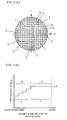
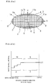
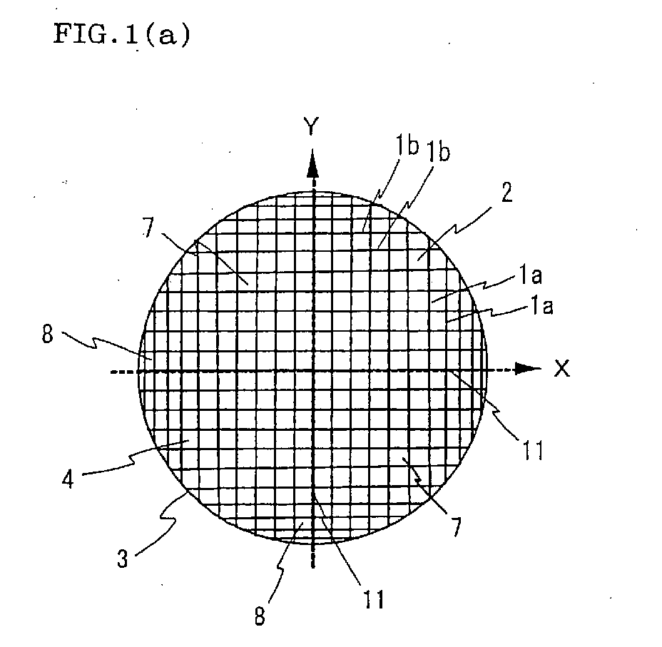
- a honeycomb structure of the present invention includes a cell structure section 3 including a plurality of cells 2 partitioned by a plurality of partition walls 1a and 1b, and an outer circumferential wall section 4 surrounding the cell structure section 3.
- a honeycomb structure of the present invention includes a cell structure section 3 including a plurality of cells 2 partitioned by a plurality of partition walls 1a and 1b, and an outer circumferential wall section 4 surrounding the cell structure section 3.
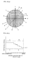
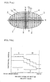
- the cell structure section 3 has a structure in which the partition wall 1 connects two different locations of the outer circumferential wall section 4 through one continuous plane, and includes a first partition wall group having the partition walls 1a positioned in parallel (hereinafter simply referred to as "first partition wall group”) and a second partition wall group having the partition walls 1b which intersect the partition walls of the first partition wall group at right angles and are positioned in parallel (hereinafter simply referred to as "second partition wall group”), in which all the partition walls preferably belong to either the first partition wall group or the second partition wall group (the extending direction of the partition walls 1a of the first partition wall group is indicated by X and the extending direction of the partition walls 1b of the second the partition wall group is indicated by Y in each drawing).
- first partition wall group having the partition walls 1a positioned in parallel
- second partition wall group having the partition walls 1b which intersect the partition walls of the first partition wall group at right angles and are positioned in parallel
- the partition wall intervals of the partition walls 1a and 1b of each partition wall group positioned in parallel are varied stepwise in at least a part of the cell structure section 3, and at least some of the cells 2 partitioned by the partition walls 1a and 1b of each partition wall group have a rectangular cross-sectional shape.
- the partition wall intervals may be varied corresponding to the shape of the honeycomb structure, use mode, required performance, and the like.
- the partition wall intervals of the first partition wall group and the second partition wall group may be varied at different patterns and/or sizes or at the same pattern and/or size from a center axis position C toward the outer circumference.
- a honeycomb structure as shown in FIGS. 6(a) and 6(b) in which the partition wall intervals of the partition walls 1a of the first partition wall group and the partition walls 1b of the second partition wall group are varied at the same pattern and size from the center axis position C toward the outer circumference; a honeycomb structure as shown in FIGS. 3(a) and 3(b) and FIGS. 8(a) and 8(b) in which the partition wall intervals of either the partition walls 1a of the first partition wall group or the partition walls 1b of the second partition wall group are varied from the center axis position C toward the outer circumference, and the partition wall intervals of the other partition walls are not varied; a honeycomb structure as shown in FIGS.
- FIGS. 9(a) and 9(b) in which the partition wall intervals of the partition walls 1a of the first partition wall group and the partition walls 1b of the second partition wall group are varied at different patterns and sizes from the center axis position C toward the outer circumference; and the like can be given.
- a honeycomb structure as shown in FIGS. 7(a) and 9(b) in which the partition wall intervals of the partition walls 1a of the first partition wall group and the partition walls 1b of the second partition wall group are varied at least at different patterns or sizes from the center axis position C toward the outer circumference is preferable.
- the partition wall intervals of the partition walls 1a of the first partition wall group and the partition walls 1b of the second partition wall group may be varied at the same pattern and the same size in a part of the region from the center axis position C toward the outer circumference.
- a high exhaust gas purification performance can be obtained while securing desired isostatic strength and shock resistance by decreasing the intervals of some of the partition walls extending through the outer circumferential section and the center section to provide the high-cell-density region 8 to include a part of the outer circumferential section and the center section, and increasing the partition wall intervals extending through the remaining section to provide the low-cell-density region 7 in the remaining section, as shown in FIGS. 6 to 9.
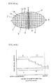
- a honeycomb structure of a type in which isostatic strength is important As a honeycomb structure of a type in which isostatic strength is important, a honeycomb structure in which the partition walls 1a and 1b of the first partition wall group and the second partition wall group are disposed at large intervals near diameter positions 11 (major axis position 11a and minor axis position 11b), and the partition walls 1a and 1b are disposed near the outer circumferential wall section 4 while decreasing the intervals stepwise toward the outer circumference to provide the high-cell-density region 8 in the outer circumferential section and to provide the low-cell-density region 7 in the center section, as shown in FIGS. 1(a) and 1(b) or FIGS. 2(a) and 2(b), can be given as a typical example.
- a honeycomb structure having an elliptical cross-sectional shape as shown in FIG. 3 can be given in which the partition wall intervals of the partition walls of the second partition wall group 6 arranged from the outer circumference having a large radius of curvature toward the major axis position 11a are increased near the major axis position 11a and are decreased stepwise near the outer circumferential wall section 4 toward the outer circumference, and the partition walls 1a of the first partition wall group 5 disposed to intersect the partition walls of the second partition wall group at right angles are disposed at equal intervals over the entire region to provide the high-cell-density region 8 near the outer circumference having a large radius of curvature and to provide the low-cell-density region 7 in the remaining region.
- the high-cell-density region is concentrated near the outer circumference having a large radius of curvature at which the external pressure during canning tends to be increased, the isostatic strength can be effectively improved.
- FIGS. 4 and 5 As a honeycomb structure of the same type, almost the same isostatic strength can be obtained by a honeycomb structure as shown in FIGS. 4 and 5 in which the partition wall intervals of the partition walls 1a of the first partition wall group and the partition walls 1b of the second partition wall group are decreased stepwise near each side of a tetragon (cross-sectional shape), which connects four locations of the outer circumferential wall section 4, and are increased in the remaining region to provide the high-cell-density region 8 near each side of the tetragonal cross-sectional shape and to provide the low-cell-density region 7 in the remaining region.
- a tetragon cross-sectional shape
- FIGS. 6(a) and 6(b) or FIGS. 7(a) and 7(b) can be given in which the partition walls 1a and 1b of the first partition wall group and the second partition wall group are disposed at large partition wall intervals in a predetermined range from the outer circumference, and the partition wall intervals of the partition walls 1a and 1b of each partition wall group are decreased stepwise near the diameter positions 11 (major axis position 11a and minor axis position 11b) to provide the high-cell-density region 8 in which the partition wall intervals are varied stepwise in the cross-shaped region including the center section and to provide the low-cell-density region 7 between the high-cell-density regions 8 in the outer circumferential section.
- cells having a rectangular cross-sectional shape can be provided at a high percentage by providing the partition walls 1a of the first partition wall group and the partition walls 1b of the second partition wall group at intervals of different sizes, whereby thermal shock resistance can be improved.
- a honeycomb structure having an elliptical cross-sectional shape as shown in FIG. 8 can be given in which all the partition walls 1b of the second partition wall group are disposed at equal partition wall intervals, and the partition wall intervals of the partition walls 1a of the first partition wall group are decreased stepwise near the minor axis position 11b to provide the high-cell-density region 8 in the center section and the outer circumferential section near the outer circumference having a large radius of curvature and to provide the low-cell-density region 7 formed by the cell structure section 3 having equal partition wall intervals on each side of the high-cell-density region 8.
- the vicinity of the outer circumference having a large radius of curvature at which the external pressure during canning of the honeycomb structure tends to be increased can be intensively reinforced, and the exhaust gas flow rate is increased near the outer circumference having a small radius of curvature in which the exhaust gas flow rate tends to be decreased, whereby the exhaust gas flow rate can be made uniform over the entire honeycomb structure.
- a honeycomb structure as shown in FIG. 9 can be given in which the partition walls 1a of the first partition wall group are disposed at large partition wall intervals in a predetermined region from the outer circumference and the partition wall intervals are decreased stepwise toward the minor axis position 11b, and the partition walls 1b of the second partition wall group are disposed at large partition wall intervals near the major axis position 11a and the partition wall intervals are decreased stepwise toward the outer circumference near the outer circumferential wall section 4 to provide the high-cell-density region 8 having a particularly high cell density near the outer circumference having a large radius of curvature, to provide the high-cell-density region 8 in the region including the center section, and to provide the low-cell-density region 7 in the remaining region.
- This honeycomb structure is preferable when higher isostatic strength is required in comparison with the honeycomb structure shown in FIG. 7.
- the partition wall intervals are varied in at least a part of the cell structure section.
- the partition wall intervals may be varied in the entire cell structure section, or may be varied in only a part of the cell structure section.
- the partition walls provided in the low-cell-density region be disposed at equal partition wall intervals as in the honeycomb structures shown in FIGS. 1(a) and 1(b) to FIGS. 9(a) and 9(b), since the catalyst contact area or the filtration area is not decreased to a large extent, whereby desired exhaust gas purification performance can be secured.
- the partition wall intervals there are no specific limitations as to the degree of change in the partition wall interval in the region in which the partition wall intervals are varied.
- the partition wall intervals be varied geometrically or arithmetically. If the partition wall intervals are locally and rapidly varied, since the cell rigidity is rapidly varied in that area, mechanical shock or thermal shock tends to be concentrated in that area, whereby isostatic strength and thermal shock resistance tends to be decreased.
- the partition wall interval variation ratio (
- the "next partition wall interval” used herein means the interval between the next adjacent partition walls.
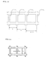
- the reference partition wall interval is an interval (s) between a partition wall 1a 1 and a partition wall 1a 2 in FIG. 10
- the next partition wall interval is an interval (n) between a partition wall 1a 2 and a partition wall 1a 3 .
- the reference interval is the interval (n)
- an interval (n+1) between the partition wall 1a 3 and a partition wall 1a 4 adjacent to the partition wall 1a 3 is the next partition wall interval.
- a ratio of a cell side length (length of each side of a cell) L to a partition wall thickness (t) (cell side length (L) / partition wall thickness (t); hereinafter referred to as "length/thickness ratio") of all the partition walls be a value which allows the partition wall to withstand the pressure during canning while varying the partition wall intervals.
- length/thickness ratio a ratio of a cell side length (length of each side of a cell) L to a partition wall thickness (t) (cell side length (L) / partition wall thickness (t); hereinafter referred to as "length/thickness ratio" of all the partition walls be a value which allows the partition wall to withstand the pressure during canning while varying the partition wall intervals.
- the partition wall thickness (t) of the partition wall having a large cell side length (L) as in the low-density region or the like corresponding to the cell side length it is preferable that the square of the length/thickness ratio not exceed 1000, and it is
- a conventional partition wall formed of a cordierite material may be densified by causing a material including some of the components of the cordierite material to adhere to the partition wall and causing melting to occur during firing due to a decrease in melting point, for example.
- the number of cells having a rectangular cross-sectional shape be large, since the thermal shock resistance is increased and the catalytic performance or adsorption performance can be improved. It is preferable that the cell 2 located in the outer circumferential section of the honeycomb structure have a flattening ratio (long side length/short side length) of 2 or less, and still more preferably 1.2 or less.
- the flattening ratio (long side length/short side length) of the cell 2 located in the outer circumferential section is within this range, the bending strength of the cell structure section 3 located in the outer circumferential section can be improved, whereby desired isostatic strength of the honeycomb structure can be obtained. Therefore, it is also preferable that the cell 2 located in the outer circumferential section have a regular square cross-sectional shape.
- the flattening ratio (long side length/short side length) of the cell exceeds 1.2, the strength of the partition wall can be sufficiently secured when the flattening ratio is 2.0 or less by increasing the thickness of the partition wall or densifying the partition wall.
- the flattening ratio (long side length/short side length) of the cell be 1.2 or less.
- a metal material or at least one ceramic material selected from the group consisting of cordierite, alumina, mullite, lithium aluminum silicate, aluminum titanate, titania, zirconia, silicon nitride, aluminum nitride, and silicon carbide, or at least one adsorbent material such as activated carbon, silica gel, or zeolite can be given.
- the shape of the honeycomb structure of the present invention is not particularly limited.
- the cross-sectional shape of the honeycomb structure may be circular, elliptical, oval, or a non-symmetrical irregular shape.
- the honeycomb structure of the present invention is described above.
- the honeycomb structure may be formed into a honeycomb filter by alternately plugging end faces of the cells using a plugging material formed of the same material as the material for the honeycomb structure, for example.
- a catalyst body or an adsorbent may be formed by loading a catalyst such as Pt, Pd, or Rh on the partition walls of the honeycomb structure.
- An exhaust gas purification converter may be formed by holding the honeycomb structure, the honeycomb filter, or the catalyst body in a casing, and providing an exhaust gas introduction tube for introducing exhaust gas into the honeycomb structure or the like.
- a die suitably used to manufacture the above-described honeycomb structure of the present invention is described below.
- a die 30 of the present invention includes lattice-shaped slits 22 which are open on one face A of a die substrate 21, and a plurality of holes 24 which are open on an opposite face B of the die substrate 21, each of the holes introducing a raw material into a specific region of the lattice-shaped slits 22, wherein open slit areas per unit lattice are varied stepwise in at least some of the lattice-shaped slits 22, the die 30 including a structure which varies flow rates of the raw material introduced into regions having different open slit areas per unit lattice at a ratio almost equal to a variation ratio of the open slit areas.
- the holes 24 are usually formed in the die for forming a honeycomb structure so that each of the holes 24 communicates with each intersection 25 of the lattice-shaped slits 22.
- the flow rate of the raw material introduced into the next intersection 25b be varied from the flow rate of the raw material introduced into the one intersection 25a.
- the "open slit area with a central point on the intersection” used herein means the area of the slit opening in the range which starts from the one intersection 25a and ends at the midpoint of a straight line which connects the one intersection 25a with each of the adjacent intersections 25b to 25e, as shown in FIG. 12 (indicated by right-slanting lines in the drawing).
- the structure which varies the flow rates of the raw material introduced into the regions having different open slit areas per unit lattice corresponding to the variation ratio of the open slit areas in the die shown in FIG. 12, the structure which, corresponding to the variation ratio, to the open slit area with a central point on one intersection of the lattice-shaped slits, of the open slit area with a central point on the next intersection adjacent to the one intersection, varies the flow rate of the raw material introduced into the next intersection from the flow rate of the raw material introduced into the one intersection)
- a structure in which at least one of intervals of the holes 24, inner diameters "m” of the holes 24, and raw material path lengths "s" of the holes 24 is varied can be given, for example.
- a die in which the inner diameters "m" of the holes 24 or the raw material path lengths "s" of the holes 24 are varied is preferable, since it is possible to flexibly deal with a comparatively small change in the open slit area by simply changing the structure.
- a die in which the intervals of the holes 24 are varied is preferable.
- a die may be provided in which the intervals of the holes are varied corresponding to the variation ratio of the open slit areas, such as a die in which the holes 24 are provided to every other intersection 25 in the slit section corresponding to the partition walls present in the low-cell-density region shown in FIG. 14(a) in which the partition wall intervals are large, and the holes 24 are provided to all the intersections 25 in the slit section corresponding to the partition walls present in the high-cell-density region shown in FIG. 14(b) in which the partition wall intervals are small.
- the inner diameters of the holes 24 are varied or a die in which the raw material path lengths of the holes are varied, it is preferable to appropriately set the inner diameters "m” or the raw material path lengths "s" of the holes 24 corresponding to the raw material pressure applied to the holes 24, the slit width, or the like so that the raw material flow rate can be easily adjusted while preventing a considerable increase in the raw material pressure.
- the die forming material, the slit width, the manufacturing method, and the like may be selected from those usually selected.
- Kneaded clay containing a cordierite-forming raw material as a major component was prepared according to a conventional method.
- the resulting clay was extruded using a die for forming a honeycomb structure having a shape as shown in FIG. 1(a), dried, and fired to prepare a honeycomb structure.
- the resulting honeycomb structure was in the shape of a column having a diameter of about 130 mm and a length of 150 mm, in which the porosity was 25%, the thickness of the outer circumference wall was 0.3 mm, and the partition wall thickness was 0.06 mm.
- the outermost circumferential partition wall interval (first) was set to 0.85 mm
- the next adjacent partition wall interval (second) was set to 0.88 mm
- the partition wall intervals for 10 cells were sequentially varied geometrically.
- the subsequent partition wall interval was fixed at 1.27 mm.
- Table 1 shows the partition wall intervals and the like in the 10-cell region, specifically, in a partition wall interval change region 10 shown in FIG. 1(b), and the partition wall interval in a partition wall interval fixed region 9.
- Partition wall interval Partition wall interval variation ratio Cell flattening ratio (Cell side length / partition wall thickness) 2 Outermost circumferential partition walls (first) 0.85 0.04 1.5 407 Second 0.88 0.04 1.4 407 Third 0.92 0.04 1.4 407 Fourth 0.96 0.04 1.3 407 Fifth 0.99 0.04 1.3 407 Sixth 1.03 0.04 1.2 407 Seventh 1.08 0.04 1.2 407 Eighth 1.12 0.04 1.1 407 Ninth 1.16 0.04 1.1 407 Tenth 1.21 0.05 1.0 407 Partition wall interval fixed region 1.27
- a honeycomb structure was prepared in the same manner as in Example 1 except for changing the partition wall thickness as shown in Table 2.
- Partition wall thickness (mm) (Cell side length / partition wall thickness) 2 Isostatic fracture strength test result
- Example 1 0.06 407 Did not fracture
- Example 2 0.05 595 Did not fracture
- Example 3 0.04 946 Did not fracture Comparative
- Comparative Example 1 0.035 1245 Fractured Comparative Example 2 0.03 1708
- honeycomb structures obtained in Examples 1 to 3 and Comparative Examples 1 and 2 were subjected to an isostatic fracture strength test at a pressure of 0.5 MPa to observe the presence or absence of fracture. The results are shown in Table 2.
- the honeycomb structures of Examples 1 to 3 in which the square of (cell side length/partition wall thickness) was less than 1000 did not fracture during the isostatic fracture strength test and were confirmed to be able to withstand the pressure during canning.
- a honeycomb structure was prepared in the same manner as in Example 1 except for changing the outermost circumferential partition wall interval as shown in Table 3 and changing the partition wall interval variation ratio corresponding to the outermost circumferential partition wall interval.
- the resulting honeycomb structure was subjected to the isostatic fracture strength test in the same manner as in Example 1 to observe the presence or absence of fracture. The results are shown in Table 3.
- the honeycomb structures of Examples 1, 4, and 5 in which the maximum value of the cell flattening ratio was 2.0 or less did not fracture and were confirmed to be able to withstand the pressure during canning.
- the honeycomb structures of Comparative Examples 3 and 4 in which the maximum value of the cell flattening ratio exceeded 2.0 fractured and were confirmed to be not able to withstand the pressure during canning.
- a honeycomb structure was prepared in the same manner as in Example 1 except for changing the outermost circumferential partition wall interval to 0.7 mm, changing the partition wall interval in the partition wall interval fixed region to 1.27 mm, and varying the partition wall intervals for two cells or three cells at a variation ratio shown in Table 4.
- the resulting honeycomb structure was subjected to a thermal shock test by heating the honeycomb structure at 800°C for 30 minutes in an electric furnace and removing the honeycomb structure from the electric furnace to observe the presence or absence of fracture of the honeycomb structure. The results are shown in Table 4.
- a cordierite honeycomb structure was prepared in the same manner as in Example 1 except for changing the partition wall thickness to 0.05 mm, changing the outermost partition wall interval (first) to 0.7 mm, sequentially varying the partition wall intervals for nine cells geometrically at a variation ratio shown in Table 5, and changing the partition wall interval in the partition wall interval fixed region to 1.04 mm.
- Partition wall interval Partition wall interval variation ratio Cell flattening ratio (Cell side length / partition wall thickness) 2 Outermost circumferential partition walls (first) 0.73 0.04 1.4 392 Second 0.76 0.04 1.4 392 Third 0.79 0.04 1.3 392 Fourth 0.82 0.04 1.3 392 Fifth 0.85 0.04 1.2 392 Sixth 0.89 0.04 1.2 392 Seventh 0.92 0.04 1.1 392 Eighth 0.96 0.04 1.1 392 Ninth 1.00 0.04 1.0 392 Partition wall interval fixed region 1.04
- a cordierite honeycomb structure was prepared in the same manner as in Example 1 except for changing the partition wall thickness to 0.04 mm, changing the outermost partition wall interval (first) to 0.70 mm, sequentially varying the partition wall intervals for 10 cells geometrically at a variation ratio shown in Table 5, and changing the partition wall interval in the partition wall interval fixed region to 0.85 mm.
- Partition wall interval Partition wall interval variation ratio Cell flattening ratio (Cell side length / partition wall thickness) 2 Outermost circumferential partition walls (first) 0.70 0.02 1.2 410 Second 0.71 0.02 1.2 410 Third 0.73 0.02 1.2 410 Fourth 0.74 0.02 1.1 410 Fifth 0.76 0.02 1.1 410 Sixth 0.77 0.02 1.1 410 Seventh 0.79 0.02 1.1 410 Eighth 0.80 0.02 1.1 410 Ninth 0.82 0.02 1.0 410 Tenth 0.84 0.02 1.0 410 Partition wall interval fixed region 0.85
- a honeycomb structure was prepared in the same manner as in Example 1 except for changing the diameter to about 200 mm, changing the length to 170 mm, changing the porosity to 65%, changing the partition wall thickness to 0.3 mm, forming the outer circumference wall using a ceramic cement coat, alternately plugging the cells, changing the outermost partition wall interval (first) to 1.00 mm, sequentially varying the partition wall intervals for five cells geometrically, and changing the partition wall interval in the partition wall interval fixed region to 1.47 mm as shown in Table 7.
- Partition wall interval Partition wall interval variation ratio Cell flattening ratio (Cell side length / partition wall thickness) 2 Outermost circumferential partition walls (first) 1.00 0.10 1.5 15 Second 1.10 0.10 1.3 15 Third 1.21 0.10 1.2 15 Fourth 1.33 0.10 1.1 15 Fifth 1.46 0.00 1.0 15 Partition wall interval fixed region 1.47
- a honeycomb structure was prepared in the same manner as in Example 12 except for changing the partition wall intervals for four cells from the outer circumference as shown in Table 8.
- Partition wall interval (mm) Partition wall interval variation ratio Cell flattening ratio (Cell side length / partition wall thickness) 2
- Outermost circumferential partition walls (first) 1.00 0.15 1.5 15 Second 1.15 0.15 1.3 15
- honeycomb structures obtained in Examples 10 to 13 were subjected to the isostatic fracture strength test at a pressure of 0.5 MPa to observe the presence or absence of fracture. As a result, since these honeycomb structures did not fracture, it was confirmed that these honeycomb structures can withstand the pressure during canning.
- a honeycomb structure which excels in isostatic strength and thermal shock resistance and has such a high industrial applicability that the honeycomb structure can be manufactured at low cost can be provided.
- a die for forming a honeycomb structure which enables such a honeycomb structure to be manufactured without causing a forming failure can be provided.
Landscapes
- Chemical & Material Sciences (AREA)
- Engineering & Computer Science (AREA)
- Chemical Kinetics & Catalysis (AREA)
- Geometry (AREA)
- Physics & Mathematics (AREA)
- Mechanical Engineering (AREA)
- Ceramic Engineering (AREA)
- Combustion & Propulsion (AREA)
- General Engineering & Computer Science (AREA)
- Health & Medical Sciences (AREA)
- Toxicology (AREA)
- Environmental & Geological Engineering (AREA)
- Analytical Chemistry (AREA)
- Materials Engineering (AREA)
- Biomedical Technology (AREA)
- Organic Chemistry (AREA)
- General Chemical & Material Sciences (AREA)
- Oil, Petroleum & Natural Gas (AREA)
- Manufacturing & Machinery (AREA)
- Catalysts (AREA)
- Press-Shaping Or Shaping Using Conveyers (AREA)
- Exhaust Gas After Treatment (AREA)
- Exhaust Gas Treatment By Means Of Catalyst (AREA)
Abstract
Description
| Partition wall interval (mm) | Partition wall interval variation ratio | Cell flattening ratio | (Cell side length / partition wall thickness)2 | |
| Outermost circumferential partition walls (first) | 0.85 | 0.04 | 1.5 | 407 |
| Second | 0.88 | 0.04 | 1.4 | 407 |
| Third | 0.92 | 0.04 | 1.4 | 407 |
| Fourth | 0.96 | 0.04 | 1.3 | 407 |
| Fifth | 0.99 | 0.04 | 1.3 | 407 |
| Sixth | 1.03 | 0.04 | 1.2 | 407 |
| Seventh | 1.08 | 0.04 | 1.2 | 407 |
| Eighth | 1.12 | 0.04 | 1.1 | 407 |
| Ninth | 1.16 | 0.04 | 1.1 | 407 |
| Tenth | 1.21 | 0.05 | 1.0 | 407 |
| Partition wall interval fixed region | 1.27 |
| Partition wall thickness (mm) | (Cell side length / partition wall thickness)2 | Isostatic fracture strength test result | |
| Example 1 | 0.06 | 407 | Did not fracture |
| Example 2 | 0.05 | 595 | Did not fracture |
| Example 3 | 0.04 | 946 | Did not fracture |
| Comparative Example 1 | 0.035 | 1245 | Fractured |
| Comparative Example 2 | 0.03 | 1708 | Fractured |
| Outermost circumferential partition wall interval (mm) | Cell flattening ratio (maximum value) | Isostatic fracture strength test result | |
| Example 1 | 0.85 | 1.5 | Did not fracture |
| Example 4 | 0.70 | 1.8 | Did not fracture |
| Example 5 | 0.65 | 2.0 | Did not fracture |
| Comparative Example 3 | 0.60 | 2.1 | Fractured |
| Comparative Example 4 | 0.55 | 2.3 | Fractured |
| Example | Partition wall interval (mm) | Partition wall interval variation ratio | Cell flattening ratio | Electric furnace test result | |
| 6 | Outermost circumferential partition walls (first) | 0.70 | 0.30 | 1.8 | Cracks did not occur |
| Second | 0.91 | 0.30 | 1.4 | ||
| Third | 1.18 | 0.07 | 1.1 | ||
| Partition wall interval fixed region | 1.27 | ||||
| 7 | Outermost circumferential partition walls (first) | 0.70 | 0.40 | 1.8 | Cracks did not occur |
| Second | 0.98 | 0.30 | 1.4 | ||
| Partition wall interval fixed region | 1.27 | ||||
| 8 | Outermost circumferential partition walls (first) | 0.70 | 0.50 | 1.8 | Cracks did not occur |
| Second | 1.05 | 0.21 | 1.4 | ||
| Partition wall interval fixed region | 1.27 | ||||
| 9 | Outermost circumferential partition walls (first) | 0.70 | 0.60 | 1.8 | Cracks occurred Cracks occurred |
| Second | 1.12 | 0.13 | 1.4 | ||
| Partition wall interval fixed region | 1.27 |
| Partition wall interval (mm) | Partition wall interval variation ratio | Cell flattening ratio | (Cell side length / partition wall thickness)2 | |
| Outermost circumferential partition walls (first) | 0.73 | 0.04 | 1.4 | 392 |
| Second | 0.76 | 0.04 | 1.4 | 392 |
| Third | 0.79 | 0.04 | 1.3 | 392 |
| Fourth | 0.82 | 0.04 | 1.3 | 392 |
| Fifth | 0.85 | 0.04 | 1.2 | 392 |
| Sixth | 0.89 | 0.04 | 1.2 | 392 |
| Seventh | 0.92 | 0.04 | 1.1 | 392 |
| Eighth | 0.96 | 0.04 | 1.1 | 392 |
| Ninth | 1.00 | 0.04 | 1.0 | 392 |
| Partition wall interval fixed region | 1.04 |
| Partition wall interval (mm) | Partition wall interval variation ratio | Cell flattening ratio | (Cell side length / partition wall thickness)2 | |
| Outermost circumferential partition walls (first) | 0.70 | 0.02 | 1.2 | 410 |
| Second | 0.71 | 0.02 | 1.2 | 410 |
| Third | 0.73 | 0.02 | 1.2 | 410 |
| Fourth | 0.74 | 0.02 | 1.1 | 410 |
| Fifth | 0.76 | 0.02 | 1.1 | 410 |
| Sixth | 0.77 | 0.02 | 1.1 | 410 |
| Seventh | 0.79 | 0.02 | 1.1 | 410 |
| Eighth | 0.80 | 0.02 | 1.1 | 410 |
| Ninth | 0.82 | 0.02 | 1.0 | 410 |
| Tenth | 0.84 | 0.02 | 1.0 | 410 |
| Partition wall interval fixed region | 0.85 |
| Partition wall interval (mm) | Partition wall interval variation ratio | Cell flattening ratio | (Cell side length / partition wall thickness)2 | |
| Outermost circumferential partition walls (first) | 1.00 | 0.10 | 1.5 | 15 |
| Second | 1.10 | 0.10 | 1.3 | 15 |
| Third | 1.21 | 0.10 | 1.2 | 15 |
| Fourth | 1.33 | 0.10 | 1.1 | 15 |
| Fifth | 1.46 | 0.00 | 1.0 | 15 |
| Partition wall interval fixed region | 1.47 |
| Partition wall interval (mm) | Partition wall interval variation ratio | Cell flattening ratio | (Cell side length / partition wall thickness)2 | |
| Outermost circumferential partition walls (first) | 1.00 | 0.15 | 1.5 | 15 |
| Second | 1.15 | 0.15 | 1.3 | 15 |
| Third | 1.30 | 0.15 | 1.1 | 15 |
| Fourth | 1.45 | 0.02 | 1.0 | 15 |
| Partition wall interval fixed region | 1.47 |
Claims (17)
- A honeycomb structure, comprising:wherein the cell structure section includes a first partition wall group having the partition walls positioned in parallel, and a second partition wall group having the partition walls which intersect the partition walls of the first partition wall group at right angles and are positioned in parallel, each of the partition walls connecting two different locations of the outer circumferential wall section through one continuous plane;a cell structure section including a plurality of cells partitioned by a plurality of partition walls; andan outer circumferential wall section surrounding the cell structure section;
wherein partition wall intervals of each of the partition wall groups positioned in parallel are varied stepwise in at least a part of the cell structure section, and at least some of the cells have a rectangular cross-sectional shape; and
wherein all the partition walls have such a ratio of a cell side length to a partition wall thickness that the partition wall can withstand pressure during canning. - The honeycomb structure according to claim 1, wherein a square of the ratio of the cell side length to the partition wall thickness ((cell side length/partition wall thickness)2) of the partition walls of the cell structure section is 1,000 or less.
- The honeycomb structure according to claim 1 or 2, wherein a flattening ratio (long side length/short side length) of the cells in the cell structure section is 2.0 or less.
- The honeycomb structure according to any of claims 1 to 3, wherein the partition wall intervals of the first partition wall group are varied at a different pattern or size relative to the partition wall intervals of the second partition wall group.
- The honeycomb structure according to any of claims 1 to 4, wherein the partition wall intervals are varied geometrically in a region in which the partition wall intervals are varied stepwise.
- The honeycomb structure according to any of claims 1 to 5, wherein the partition wall intervals are varied arithmetically in a region in which the partition wall intervals are varied stepwise.
- The honeycomb structure according to any of claims 1 to 6, wherein a partition wall interval variation ratio (| next partition wall interval - reference partition wall interval | / reference partition wall interval) is 0.5 or less in a region in which the partition wall intervals are varied stepwise.
- The honeycomb structure according to any of claims 1 to 7, wherein the cells are alternately plugged on either end face.
- The honeycomb structure according to any of claims 1 to 8, wherein a catalyst component is loaded on a surface and/or inside of the partition wall.
- The honeycomb structure according to any of claims 1 to 8, wherein an adsorbent component is loaded on a surface and/or inside of the partition wall.
- The honeycomb structure according to any of claims 1 to 8, wherein a catalyst component and an adsorbent component are loaded on a surface and/or inside of the partition wall.
- An exhaust gas purification converter, comprising the honeycomb structure according to any of claims 1 to 11.
- A die for forming a honeycomb structure, the die comprising:lattice-shaped slits which are open on one face of a die substrate; anda plurality of holes which are open on an opposite face of the die substrate, each of the holes introducing a raw material into a specific region of the lattice-shaped slits;wherein open slit areas per unit lattice are varied stepwise in at least some of the lattice-shaped slits;the die including a structure which varies flow rates of the raw material introduced into regions having different open slit areas per unit lattice at a ratio substantially equal to a variation ratio of the open slit areas.
- The die for forming a honeycomb structure according to claim 13, wherein the structure which varies the flow rates of the raw material introduced into the regions is a structure in which at least one of intervals of the holes, inner diameters of the holes, and raw material path lengths of the holes is varied.
- A die for forming a honeycomb structure, the die comprising:lattice-shaped slits which are open on one face of a die substrate; anda plurality of holes which are open on an opposite face of the die substrate, the holes communicating with intersections of the lattice-shaped slits;wherein open slit areas around the intersections of the lattice-shaped slits are varied stepwise in at least some of the lattice-shaped slits;the die including a structure which, at a ratio substantially equal to a variation ratio of the open slit area around a next intersection adjacent to one intersection of the lattice-shaped slits to the open slit area around the one intersection (next intersection/one intersection), varies a flow rate of the raw material introduced into the next intersection from a flow rate of the raw material introduced into the one intersection.
- The die for forming a honeycomb structure according to claim 15, wherein the structure which varies the flow rate of the raw material introduced into the next intersection is a structure in which at least one of intervals of the holes, inner diameters of the holes, and raw material path lengths of the holes is varied.
- The die for forming a honeycomb structure according to claim 15, wherein the structure which varies the flow rate of the raw material introduced into the next intersection is a structure in which intervals of the holes, inner diameters of the holes, and raw material path lengths of the holes are varied.
Applications Claiming Priority (3)
| Application Number | Priority Date | Filing Date | Title |
|---|---|---|---|
| JP2002260545 | 2002-09-05 | ||
| JP2002260545 | 2002-09-05 | ||
| PCT/JP2003/011310 WO2004026472A1 (en) | 2002-09-05 | 2003-09-04 | Honeycomb structure, and honeycomb structure forming mouthpiece |
Publications (3)
| Publication Number | Publication Date |
|---|---|
| EP1537914A1 true EP1537914A1 (en) | 2005-06-08 |
| EP1537914A4 EP1537914A4 (en) | 2006-10-25 |
| EP1537914B1 EP1537914B1 (en) | 2011-04-20 |
Family
ID=32024543
Family Applications (1)
| Application Number | Title | Priority Date | Filing Date |
|---|---|---|---|
| EP03797548A Revoked EP1537914B1 (en) | 2002-09-05 | 2003-09-04 | Honeycomb structure |
Country Status (6)
| Country | Link |
|---|---|
| US (1) | US7678439B2 (en) |
| EP (1) | EP1537914B1 (en) |
| JP (1) | JPWO2004026472A1 (en) |
| AU (1) | AU2003261937A1 (en) |
| DE (1) | DE60336824D1 (en) |
| WO (1) | WO2004026472A1 (en) |
Cited By (6)
| Publication number | Priority date | Publication date | Assignee | Title |
|---|---|---|---|---|
| EP1787702A1 (en) * | 2005-11-18 | 2007-05-23 | Ibiden Co., Ltd. | Honeycomb structured body |
| FR2896823A1 (en) * | 2006-01-31 | 2007-08-03 | Saint Gobain Ct Recherches | CATALYTIC FILTER HAVING REDUCED STARTING TIME |
| EP1837493A3 (en) * | 2006-03-20 | 2009-04-08 | Ngk Insulators, Ltd. | Honeycomb structure |
| US8178185B2 (en) | 2005-11-18 | 2012-05-15 | Ibiden Co., Ltd. | Honeycomb structured body, method for manufacturing honeycomb structured body and exhaust gas purifying device |
| WO2013111793A1 (en) * | 2012-01-27 | 2013-08-01 | Denso Corporation | Honeycomb structural body |
| US11745384B2 (en) | 2017-12-22 | 2023-09-05 | Corning, Incorporated | Multi-wall thickness, thin-walled honeycomb bodies, and extrusion dies and methods therefor |
Families Citing this family (15)
| Publication number | Priority date | Publication date | Assignee | Title |
|---|---|---|---|---|
| JP4937534B2 (en) * | 2005-06-21 | 2012-05-23 | 合資会社 ヨシヒコ | Porous molded body |
| JP4841244B2 (en) * | 2005-12-22 | 2011-12-21 | 京セラ株式会社 | Honeycomb structure and filter using the same |
| US8545763B2 (en) * | 2010-01-29 | 2013-10-01 | Honda Motor Co., Ltd. | Catalytic converter substrate structure |
| JP6041476B2 (en) * | 2011-10-28 | 2016-12-07 | 住友化学株式会社 | Honeycomb structure |
| CN102808531B (en) * | 2012-08-23 | 2014-10-15 | 成都赛珞仓储工程设计有限公司 | Hollow vertical-wall combined square rectangular silo |
| JP2014181143A (en) * | 2013-03-18 | 2014-09-29 | Ngk Insulators Ltd | Honeycomb structure |
| US9663408B2 (en) * | 2013-09-26 | 2017-05-30 | Ngk Insulators, Ltd. | Honeycomb structure |
| WO2016144714A2 (en) | 2015-03-06 | 2016-09-15 | Corning Incorporated | Extrusion dies and methods and apparatuses for forming the same |
| JP2016175789A (en) * | 2015-03-19 | 2016-10-06 | 日本碍子株式会社 | Honeycomb structure |
| EP3381546A1 (en) * | 2017-03-29 | 2018-10-03 | Vito NV | Devices for through-flow of fluids comprising graded porous structures |
| JP7003694B2 (en) * | 2018-01-30 | 2022-01-20 | 株式会社デンソー | Honeycomb structure |
| JP6570678B2 (en) * | 2018-02-27 | 2019-09-04 | 本田技研工業株式会社 | Filter carrier |
| JP2020044461A (en) * | 2018-09-14 | 2020-03-26 | 三菱日立パワーシステムズ株式会社 | Denitrification device |
| EP3924566A1 (en) * | 2019-02-13 | 2021-12-22 | ENI S.p.A. | Barrier assembly |
| JP7594471B2 (en) * | 2021-03-16 | 2024-12-04 | 日本碍子株式会社 | Honeycomb structure and electrically heated carrier |
Family Cites Families (29)
| Publication number | Priority date | Publication date | Assignee | Title |
|---|---|---|---|---|
| US3853485A (en) | 1972-12-11 | 1974-12-10 | Corning Glass Works | Core member for catalytic oxidation converter |
| JPS5910289B2 (en) | 1977-12-24 | 1984-03-08 | 日本特殊陶業株式会社 | Extrusion die for honeycomb structure |
| JPS55155742A (en) | 1979-05-22 | 1980-12-04 | Ngk Spark Plug Co Ltd | High strength honeycomb structure |
| US4329162A (en) * | 1980-07-03 | 1982-05-11 | Corning Glass Works | Diesel particulate trap |
| JPS5719039A (en) | 1980-07-11 | 1982-02-01 | Ngk Insulators Ltd | Ceramic honeycomb structural body |
| JPS57110314A (en) | 1980-12-27 | 1982-07-09 | Canon Inc | Filter |
| JPS5928010A (en) * | 1982-08-05 | 1984-02-14 | Nippon Denso Co Ltd | Structure to purify exhaust gas |
| JPS5947310A (en) | 1982-09-09 | 1984-03-17 | Nippon Steel Corp | Method for controlling water supply to drum in waste gas treatment device for converter |
| JPS6078707A (en) | 1983-10-07 | 1985-05-04 | 日本碍子株式会社 | Ceramic honeycomb structure and manufacture thereof and rotary heat accumulation type ceramic heat exchange body utilizing said structure and extrusion molding die for said heat exchange body |
| JPS60145216A (en) | 1984-01-10 | 1985-07-31 | Sumitomo Metal Ind Ltd | Descaling method of steel strip and the like |
| JPS60147711A (en) | 1984-01-12 | 1985-08-03 | Canon Inc | auto focus device |
| JPS60147711U (en) * | 1984-03-14 | 1985-10-01 | 日産自動車株式会社 | Exhaust gas purification device for multi-cylinder engines |
| JPS6147135A (en) | 1984-08-09 | 1986-03-07 | 片山 吉一 | Production of pie like lunch |
| JPS61129016A (en) | 1984-11-28 | 1986-06-17 | Kiyataraa Kogyo Kk | Honeycomb shaped particulate collection filter, honeycomb shaped catalyst filter and preparation thereof |
| JPS6227044A (en) * | 1985-07-29 | 1987-02-05 | Ube Ind Ltd | Structural body type catalyst |
| ZA868169B (en) | 1985-10-28 | 1987-06-24 | Mabco Ltd | Detection of cystic fibrosis and monoclonal antibodies for use therein |
| JPH0659407B2 (en) | 1985-11-12 | 1994-08-10 | 松下電器産業株式会社 | Honeycomb shaped body |
| US4722819A (en) | 1986-04-28 | 1988-02-02 | W. R. Grace & Co. | Die and processes for manufacturing honeycomb structures |
| US4902216A (en) | 1987-09-08 | 1990-02-20 | Corning Incorporated | Extrusion die for protrusion and/or high cell density ceramic honeycomb structures |
| JP2502144B2 (en) | 1989-03-20 | 1996-05-29 | 日本碍子株式会社 | Manufacturing method of electric discharge machining electrode for forming honeycomb die and method for manufacturing honeycomb die |
| JP2664119B2 (en) * | 1992-11-20 | 1997-10-15 | 日本碍子株式会社 | Curved honeycomb structure |
| JP2664118B2 (en) * | 1992-11-20 | 1997-10-15 | 日本碍子株式会社 | Curved honeycomb structure |
| JP3768550B2 (en) * | 1994-03-11 | 2006-04-19 | 日本碍子株式会社 | Ceramic honeycomb structure |
| JPH09158720A (en) | 1995-12-08 | 1997-06-17 | Toyota Motor Corp | Exhaust gas purification device |
| JP3750191B2 (en) | 1996-04-26 | 2006-03-01 | イビデン株式会社 | Honeycomb mold |
| US5866080A (en) * | 1996-08-12 | 1999-02-02 | Corning Incorporated | Rectangular-channel catalytic converters |
| JP5052717B2 (en) | 2001-05-02 | 2012-10-17 | 日本碍子株式会社 | Honeycomb structure, and honeycomb filter and converter system using the same |
| JP4322542B2 (en) * | 2003-04-21 | 2009-09-02 | 日本碍子株式会社 | HONEYCOMB STRUCTURE, MANUFACTURING METHOD THEREOF, MOLDING BASE, AND EXHAUSTED FLUID PURIFICATION SYSTEM |
| JP5090751B2 (en) * | 2006-03-29 | 2012-12-05 | 日本碍子株式会社 | Honeycomb structure |
-
2003
- 2003-09-04 WO PCT/JP2003/011310 patent/WO2004026472A1/en not_active Ceased
- 2003-09-04 AU AU2003261937A patent/AU2003261937A1/en not_active Abandoned
- 2003-09-04 EP EP03797548A patent/EP1537914B1/en not_active Revoked
- 2003-09-04 US US10/525,830 patent/US7678439B2/en active Active
- 2003-09-04 JP JP2004537543A patent/JPWO2004026472A1/en active Pending
- 2003-09-04 DE DE60336824T patent/DE60336824D1/en not_active Expired - Lifetime
Cited By (8)
| Publication number | Priority date | Publication date | Assignee | Title |
|---|---|---|---|---|
| EP1787702A1 (en) * | 2005-11-18 | 2007-05-23 | Ibiden Co., Ltd. | Honeycomb structured body |
| US8178185B2 (en) | 2005-11-18 | 2012-05-15 | Ibiden Co., Ltd. | Honeycomb structured body, method for manufacturing honeycomb structured body and exhaust gas purifying device |
| FR2896823A1 (en) * | 2006-01-31 | 2007-08-03 | Saint Gobain Ct Recherches | CATALYTIC FILTER HAVING REDUCED STARTING TIME |
| WO2007088307A3 (en) * | 2006-01-31 | 2007-09-20 | Saint Gobain Ct Recherches | Catalytic filter having a short light-off time |
| EP1837493A3 (en) * | 2006-03-20 | 2009-04-08 | Ngk Insulators, Ltd. | Honeycomb structure |
| WO2013111793A1 (en) * | 2012-01-27 | 2013-08-01 | Denso Corporation | Honeycomb structural body |
| US9586195B2 (en) | 2012-01-27 | 2017-03-07 | Denso Corporation | Honeycomb structural body |
| US11745384B2 (en) | 2017-12-22 | 2023-09-05 | Corning, Incorporated | Multi-wall thickness, thin-walled honeycomb bodies, and extrusion dies and methods therefor |
Also Published As
| Publication number | Publication date |
|---|---|
| AU2003261937A1 (en) | 2004-04-08 |
| US20050241266A1 (en) | 2005-11-03 |
| DE60336824D1 (en) | 2011-06-01 |
| EP1537914B1 (en) | 2011-04-20 |
| US7678439B2 (en) | 2010-03-16 |
| JPWO2004026472A1 (en) | 2006-01-12 |
| WO2004026472A1 (en) | 2004-04-01 |
| EP1537914A4 (en) | 2006-10-25 |
Similar Documents
| Publication | Publication Date | Title |
|---|---|---|
| US7678439B2 (en) | Honeycomb structure and die for forming honeycomb structure | |
| US7083842B2 (en) | Honeycomb structure and process for production thereof | |
| EP1486243B1 (en) | Honeycomb filter | |
| KR100604116B1 (en) | Honeycomb filter | |
| KR100637298B1 (en) | Honeycomb structural body, manufacturing method of the honeycomb structural body, and exhaust gas purifying device | |
| EP2368619B1 (en) | Ceramic honeycomb structures | |
| EP2243535B1 (en) | Honeycomb structure and bonded type honeycomb structure | |
| EP1413344A1 (en) | Honeycomb structural body | |
| EP1508354B1 (en) | Honeycomb structural body | |
| JP4657566B2 (en) | Honeycomb structure and manufacturing method thereof | |
| JP2002326035A (en) | Honeycomb structure, and honeycomb filter and converter system using the same | |
| KR20130137673A (en) | Sealed honeycomb structure, and exhaust gas purification device | |
| KR20130135929A (en) | Sealed honeycomb structure | |
| EP1600433B1 (en) | Honeycomb structure | |
| JP4238858B2 (en) | Hex honeycomb structure and manufacturing method thereof | |
| JP2018167200A (en) | Honeycomb filter | |
| JP4161292B2 (en) | Ceramic honeycomb structure | |
| JP5188436B2 (en) | Honeycomb structure | |
| CN111033005A (en) | Dimple body with radial dimple structure including transition structure parts and extrusion die therefor | |
| CN112218700A (en) | Honeycomb body with triangular channel honeycomb structure and manufacturing method thereof | |
| EP2233454B1 (en) | Honeycomb structure | |
| JP6534900B2 (en) | Honeycomb structure | |
| KR20210050550A (en) | Ceramic honeycomb structure and mold for honeycomb molding | |
| WO2016052680A1 (en) | Ceramic honeycomb structure, manufacturing method therefor, and honeycomb molding mold | |
| US10478766B2 (en) | Honeycomb filter |
Legal Events
| Date | Code | Title | Description |
|---|---|---|---|
| PUAI | Public reference made under article 153(3) epc to a published international application that has entered the european phase |
Free format text: ORIGINAL CODE: 0009012 |
|
| 17P | Request for examination filed |
Effective date: 20050329 |
|
| AK | Designated contracting states |
Kind code of ref document: A1 Designated state(s): AT BE BG CH CY CZ DE DK EE ES FI FR GB GR HU IE IT LI LU MC NL PT RO SE SI SK TR |
|
| AX | Request for extension of the european patent |
Extension state: AL LT LV MK |
|
| DAX | Request for extension of the european patent (deleted) | ||
| RBV | Designated contracting states (corrected) |
Designated state(s): DE FR |
|
| A4 | Supplementary search report drawn up and despatched |
Effective date: 20060925 |
|
| 17Q | First examination report despatched |
Effective date: 20070711 |
|
| RTI1 | Title (correction) |
Free format text: HONEYCOMB STRUCTURE |
|
| GRAP | Despatch of communication of intention to grant a patent |
Free format text: ORIGINAL CODE: EPIDOSNIGR1 |
|
| GRAC | Information related to communication of intention to grant a patent modified |
Free format text: ORIGINAL CODE: EPIDOSCIGR1 |
|
| R17C | First examination report despatched (corrected) |
Effective date: 20070711 |
|
| GRAS | Grant fee paid |
Free format text: ORIGINAL CODE: EPIDOSNIGR3 |
|
| GRAA | (expected) grant |
Free format text: ORIGINAL CODE: 0009210 |
|
| AK | Designated contracting states |
Kind code of ref document: B1 Designated state(s): DE FR |
|
| REF | Corresponds to: |
Ref document number: 60336824 Country of ref document: DE Date of ref document: 20110601 Kind code of ref document: P |
|
| REG | Reference to a national code |
Ref country code: DE Ref legal event code: R096 Ref document number: 60336824 Country of ref document: DE Effective date: 20110601 |
|
| PLBI | Opposition filed |
Free format text: ORIGINAL CODE: 0009260 |
|
| PLAX | Notice of opposition and request to file observation + time limit sent |
Free format text: ORIGINAL CODE: EPIDOSNOBS2 |
|
| 26 | Opposition filed |
Opponent name: EMITEC GESELLSCHAFT FUER EMISSIONSTECHNOLOGIE MBH Effective date: 20120120 |
|
| REG | Reference to a national code |
Ref country code: DE Ref legal event code: R026 Ref document number: 60336824 Country of ref document: DE Effective date: 20120120 |
|
| REG | Reference to a national code |
Ref country code: FR Ref legal event code: ST Effective date: 20120531 |
|
| PLBB | Reply of patent proprietor to notice(s) of opposition received |
Free format text: ORIGINAL CODE: EPIDOSNOBS3 |
|
| PG25 | Lapsed in a contracting state [announced via postgrant information from national office to epo] |
Ref country code: FR Free format text: LAPSE BECAUSE OF NON-PAYMENT OF DUE FEES Effective date: 20110930 |
|
| REG | Reference to a national code |
Ref country code: DE Ref legal event code: R064 Ref document number: 60336824 Country of ref document: DE Ref country code: DE Ref legal event code: R103 Ref document number: 60336824 Country of ref document: DE |
|
| PGFP | Annual fee paid to national office [announced via postgrant information from national office to epo] |
Ref country code: DE Payment date: 20130829 Year of fee payment: 11 |
|
| RDAF | Communication despatched that patent is revoked |
Free format text: ORIGINAL CODE: EPIDOSNREV1 |
|
| RDAG | Patent revoked |
Free format text: ORIGINAL CODE: 0009271 |
|
| STAA | Information on the status of an ep patent application or granted ep patent |
Free format text: STATUS: PATENT REVOKED |
|
| 27W | Patent revoked |
Effective date: 20131014 |
|
| REG | Reference to a national code |
Ref country code: DE Ref legal event code: R107 Ref document number: 60336824 Country of ref document: DE Effective date: 20140508 |