EP1537768B1 - Seeder equiped with a seed counter device - Google Patents
Seeder equiped with a seed counter device Download PDFInfo
- Publication number
- EP1537768B1 EP1537768B1 EP20040300829 EP04300829A EP1537768B1 EP 1537768 B1 EP1537768 B1 EP 1537768B1 EP 20040300829 EP20040300829 EP 20040300829 EP 04300829 A EP04300829 A EP 04300829A EP 1537768 B1 EP1537768 B1 EP 1537768B1
- Authority
- EP
- European Patent Office
- Prior art keywords
- seeds
- seeder according
- seed
- counted
- flow
- Prior art date
- Legal status (The legal status is an assumption and is not a legal conclusion. Google has not performed a legal analysis and makes no representation as to the accuracy of the status listed.)
- Expired - Fee Related
Links
Images


Classifications
-
- A—HUMAN NECESSITIES
- A01—AGRICULTURE; FORESTRY; ANIMAL HUSBANDRY; HUNTING; TRAPPING; FISHING
- A01C—PLANTING; SOWING; FERTILISING
- A01C7/00—Sowing
- A01C7/08—Broadcast seeders; Seeders depositing seeds in rows
- A01C7/10—Devices for adjusting the seed-box ; Regulation of machines for depositing quantities at intervals
- A01C7/102—Regulating or controlling the seed rate
- A01C7/105—Seed sensors
Definitions
- the present invention relates to the general technical field of agricultural machinery and in particular to dispensing machines. It relates more particularly to a drill according to claim 1.
- Such a drill is known in Lemken's special edition entitled “ Körner pro Quadratmeter Statt Kilogram Pro Hektar ".
- This seed drill comprises in a manner known per se a hopper, a metering device, a dispensing head fed from the metering device by means of a pipe, a plurality of seed implantation members into the ground and connecting pipes. the dispensing head to the implantation members.
- This seed drill additionally comprises a seed counting device consisting of an alignment device and a seed counter.
- the seed counting device additionally comprises a device for separating the seeds from the air flow.
- This separation device is constituted by a cyclone. The cyclone has at its upper part an orifice through which the air escapes.
- the seed counter transmits the number of seeds to a terminal which compares this number with the number of seeds to be sown.
- the terminal also controls the dosing device. The counted seeds are then reinjected into the hopper.
- the alignment device consists of two rollers. These rollers are rotated to individualize the seeds to count. The seeds fall from the container on these two rollers driven in rotation and are thus aligned to be recorded by the photocell. The space between the two rolls is adaptable to the size of the seeds.
- the realization of this alignment device is complex, especially because there is a drive mechanism of the two rollers.
- the document DE 101 34 991 describes another device for counting seeds.
- the known drill includes in particular a device for aligning seeds to count and a seed counter.
- the alignment device is disposed in the lower part of a container that receives the seeds to count. It is a disk with holes at the periphery to receive the seeds. The seeds are sucked on the holes to be counted then ejected to the hopper.
- This seed counting device uses the known technology of the distribution on the precision seeding machines.
- this seed counting device For the operation of this seed counting device, it is necessary firstly to drive the disk with holes in rotation and secondly to install a suction under the disk with holes so that the seeds are sucked on the holes to be counted.
- the disc still has a seed selector and a seed ejector.
- the holes of the discs must be adapted to the different types of seeds to be counted.
- the realization of this seed counting device is also complicated.
- EP 1 341 122 The planter of the type described in the document is also known.
- EP 1 341 122 With such a precision seed drill, the seeds are already individualized one by one during the dosage and the initial spacing between the seeds is maintained by the pipe which brings the seeds one by one to the implant member. The seeds are counted one by one by a counting device implanted in the pipe.
- this precision has a relatively high cost.
- the document DE 35 35 871 also discloses a seed counting device for a seed drill.
- This device is implanted between the metering device and a seed implantation member in the soil. It counts the number of seeds transported by a flow of air with a suitable seed counter. This document is silent on the realization of this device for counting seeds.
- the number of seeds obtained is transmitted to a terminal which displays a result in number of grains per square meter.
- the terminal also compares the result obtained with the defined value of seeds to be sown. It controls if necessary a motor that adjusts the dosing device.
- the present invention aims to overcome the aforementioned drawbacks. It must in particular provide a simple, economical and easily used seed counting device for all kinds of seeds usually sown by farmers, while ensuring good accuracy.
- an important characteristic of the invention consists in that said device for aligning the seeds to be counted consists of a succession of guide elements inclined one towards its next and on which said seeds slide to count.
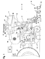
- the agricultural soil working machine shown in the figures comprises in particular a drill (1). It is more precisely a seeder of the line type as represented in FIG. figure 1 .
- This seed drill (1) is, in a non-limiting manner, connected to a device for preparing the seedbed, for example a rotary harrow (10) via a three-point coupling device (3) known from the skilled person. This combination will prepare the seedbed and sow in one pass.
- the rotary harrow (10) is then placed between the tractor (2) and the drill (1).
- the drill (1) is thus moved in a direction and a direction of advance indicated by the arrow (4) in a field to seed.
- This seed drill (1) can also be directly coupled to a tractor (2).
- This exemplary embodiment is not shown in the figures.
- the seeder (1) of the figure 1 comprises a frame (5) which is connected to the preparation apparatus of the seed bed.
- This frame (5) carries a hopper (6) containing seeds to be sown.
- This hopper (6) comprises at its base a dosing device (7) seeds.
- the metering device (7) makes it possible to precisely adjust the quantity of seeds to be deposited in the soil.
- the seeds contained in the hopper (6) are transported to implantation members (8) by means of pipes (9).
- Each implantation member (8) is formed by a hollow body in the form of a tube of rectangular section. Its front face and its base comprise a tapered part (11) so as to open a small trench in the ground.
- the upper part of each implantation member (8) has an inlet (12) which is connected to a pipe (9) and through which the seeds arrive.
- the lower part of each implantation member (8) has an outlet (13) through which said seeds are implanted in the soil.
- the implantation member (8) comprises in this embodiment, but in a nonlimiting manner, a regulating device (14) which ensures a substantially constant spacing between the seeds leaving the outlet orifice (13).
- This regulating device (14) is arranged in the body. It comprises drops (15) inclined one towards its next from the inlet (12) to the outlet (13). Said falls (15) are advantageously arranged in zigzag.
- the seeds which arrive by the pipe (9) slide, under the effect of their own weight, on said falls (15) in order to obtain a regularity of deposit of said seeds in the groove in the longitudinal direction, that is to say to say in the direction of advance (4), and in depth.
- the regulating device (14) is advantageously interchangeable, which makes it possible to adapt it to the families of seeds to be sown. Such a regulating device (14) is known to those skilled in the art and will therefore not be described in more detail.
- the seed drill (1) is of pneumatic type.
- the seed metering device (7) communicates with a feed column (16) which opens into a dispensing head (17) from which the pipes (9) leading to the implantation members (8) of the seeds which are arranged at the back across the width of the machine.
- These implantation members (8) are located, in a nonlimiting manner, in three rows and are spaced so that there are fairly regular intervals between the lines on which the seeds are deposited.
- the frame (5) of the drill (1) additionally carries a generator (18) which produces a flow of air intended to convey the seeds to be sown. This is brought by means of a conduit (19) to the base of the feed column (16). This flow of air then causes the seeds coming from the dosing device (7) to the dispensing head (17) in which it divides into several streams which engage with seeds in the pipes (9).
- Each implantation member (8) further comprises, after the inlet port (12) and the first chute (15), a separating device (20) of said seeds of the airflow carrying them.
- This separation device (20) is for example a grid (21) through which said air flow escapes.
- This grid (21) has meshes whose dimensions are smaller than those of the seeds so that the latter are retained inside the implant member (8).
- Said gate (21) is located substantially in the extension of said inlet port (12). Thus the air flow escapes and the seeds fall into the regulating device (14).
- the drill (1) comprises a seed counting device (22).
- the latter is shown schematically with a phantom frame on the figure 1 .
- This seed counting device (22) is here connected to one of the pipes (9) leading to a corresponding implantation member (8).
- the Figures 2 to 5 are schematic representations of various embodiments of a seed counting device (22) adapted to a specific seed drill and connected to different locations on the drill.
- This seed counting device (22) must allow, in a relatively simple manner, to obtain the number of seed sown.
- It comprises, for this purpose, a seed alignment device (23) and a seed counter (24).
- the alignment device (23) makes it possible to align the seeds one behind the other so that a standard seed counter (24) can locate and count them.
- the seed counter (24) is therefore disposed downstream of said alignment device (23).
- the alignment device (23) for the seeds to be counted consists of a series of guide elements (25) inclined one towards its next and on which the seeds slide from to align them.
- two consecutive guide elements (25) form between them an angle (alpha) of between 60 ° and 100 °. It varies according to the type of seeds to be sown.
- an angle (alpha) of between 60 ° and 100 °. It varies according to the type of seeds to be sown.
- At least three consecutive guide elements (25) are used.
- a grouping ramp (26) is arranged upstream the first guide element (25). Its function is to receive the seeds that arrive through the pipe (9) and to ensure that they fall at the top of the first guide element (25).
- This grouping ramp (26) has a flat cross section.
- the guide elements (25) have, for their part, advantageously a shape of gutters for guiding the seeds.
- the seeds thus slide from one guide element (25) towards the other to be aligned at the outlet of the last guide element (25).
- Said gutters have a V-shaped profile with an opening angle (beta) of between 50 ° and 70 °.
- An opening angle (beta) of 60 ° gives a very good result of guiding seeds.
- the guiding of the small seeds is improved when the guide elements (25) have a V-shaped cross section with a rounded bottom. It is important that at least the last guide member (25) has a gutter shape.
- the different guide elements (25) of the counting seed alignment device (23) are grouped into a single piece (27), for example in the form of a cassette (28).
- This single piece (27) could be advantageously provided removable and interchangeable, which allows to adapt the seed counting device (22) to families of seeds to count.
- the cassette (28) shown in figure 2 suitable for sowing large diameter seeds such as wheat or barley.
- the cassette (28) has three guide elements (25).
- the angle (alpha) between two consecutive guide elements is variable. Between the first and the second guide elements (25), the angle (alpha) is close to 70 ° while the angle (alpha) between the second and the last guide elements (25) is substantially equal to 90 ° .
- the bottom of the gutter of these guide elements (25) is rounded.
- the cassette (28) shown in figure 3 is rather suitable for small diameter seeds. Note that this cassette (28) has more guide elements (25) in the form of gutters. These elements (25) have a reduced length and occupy only part of the cassette (28). The rounded bottom of the V shape is suitable for small diameters of seeds in order to better channel the seeds. The ends of these guide elements (25) are arranged closer to each other to prevent the bouncing of the seeds during the passage from one to the other. The angle (alpha) between two consecutive guide elements (25) is here preferably identical for all the guide elements.
- the seed counting device (22) fits on one of the pipes (9).
- the seeds passing through said pipe (9) enter the cassette (28), slide on the guide elements (25) to be aligned and are then counted as output by the seed counter (24). These seeds then continue their way until they reach the ground.
- the seed counting device (22) is implanted on the pipe (9) upstream of said implantation member (8).
- the figure 2 schematically represents a first embodiment of the invention.
- the seed counting device (22) of the figure 2 is suitable for a pneumatic type seed drill (1) as shown in FIG. figure 1 .
- the combined agricultural machine according to figure 1 is attached to the tractor (2) which allows to move on a field and animate it.
- the implantation members (8) open small furrows in the soil in which the seeds are deposited. These pass from the hopper (6) into the feed column (16) through a respective metering device of the metering device (7). In said column (16), they are driven by the air flow produced by the generator (18). This air flow arrives in the head (17) which distributes to the pipes (9). In the latter the seeds are taken to the implantation organs (8).
- the seed counting device (22) is connected to one of these pipes (9).
- the seeds of this pipe (9) therefore first pass into the seed alignment device (23) to be counted by the seed counter (24) before continuing their progression in said pipe (9) towards the implantation member (8) corresponding and be deposited in the groove opened by this implantation member (8).
- the airflow separation device (29) is made by a cyclone (29 '). This cyclone (29 ') is located upstream of the alignment device (23).
- the pipe (9) with the seeds conveyed by the air flow opens tangentially into said cyclone (29 '). It comprises in its upper part an orifice (30) through which escapes the air flow.
- the cyclone (29 ') is extended downwardly by a pipe (31) through which the seeds fall by gravity into said alignment device (23). The seeds are counted at the exit via the seed counter (24).
- the seeds Downstream of the seed counting device (22), the seeds are recovered via a funnel (34) and a flow of air is injected into the counted seed stream by means of an air injection device. (32).
- the seeds are then transported to the corresponding implantation member (8) to be implanted in the soil.
- the seeds to be counted can be conveyed by a flow of air produced by a separate generator (180).
- the air injection device (32) is directly connected to said generator (180). But this generator (180) producing a flow of air for conveying the seeds to count or seeds already counted can advantageously be constituted directly by the generator (18) producing a flow of air for conveying the seeds to be sown.
- the seed alignment at the cassette outlet (28) is optimal for the seed counter (24).
- the latter transmits the number of seeds counted to a terminal (33). He compares the number of seeds that has been counted to a number of seeds to be sown per square meter for example.
- the terminal (33) can also automatically adjust, if necessary, the metering device (7) to change the number of seed sown.
- the terminal (33) is placed in the tractor cab (2).
- the seed counter (24) is made for example by a photocell. It is generally performed by a commercially available sensor.
- Another solution for reinjecting a flow of air into the pipe (9) bringing the seeds into the soil is to use the air flow separated by the separating device (29) to reinject it into the stream of seeds counted as downstream of the seed counter (24).
- a device for reinjecting the separated air flow is therefore provided downstream of the seed counter (24).
- the seed counter could very well be functional even if the flow of seeds to be counted is not separated from the air flow, because the airflow does not really disturb the alignment of the seeds, but rather the spacing between two successive seeds which does not really affect the count.
- the seed counting device (22) is provided on one of the pipes (9) of a mechanical seed drill.
- a mechanical seed drill For seed drills of the mechanical type, the transport of seeds from the hopper (6) to said seed implantation members (8) is carried out by gravity.
- Such a drill therefore does not include a generator generating a flow of air.
- the pipes (9) are directly connected to a metering member of the metering device (7).
- the seeds leaving a dosing member fall by gravity on the grouping ramp (26) and then slide on the various guide elements (25) to be aligned at the outlet of the cassette (28).
- the seeds are then counted by a suitable counter (24) and continue to slide to the corresponding implantation member (8).
- the seed counting device (22) is arranged in such a way that the pipe (9) opens vertically to the inlet of the cassette (28) so that the seeds fall directly onto the grouping ramp (26).
- the seeds at the outlet of the cassette (28) are recovered by a funnel (34).
- the cassette (28) shown on the figure 3 is suitable for aligning seeds of small sizes.
- the seed counting device (22) is implanted directly upstream of an implantation member (8).
- This third example shows a seed counting device (22) adapted for a pneumatic seed drill. It comprises a device for separating the air flow (20) from the flow of seeds to be counted. It is made in the form of a grid (21). The flow of seeds arrives transversely with respect to the cassette (28). The seeds abut against the grid (21) which allows the flow of air to pass but retains the seeds which fall under the effect of their own weight in the alignment device (23). They fall on the grouping ramp (26) and then slide from one guide element (25) in the next to the exit where they are counted.
- the counted seeds then fall directly on the falls (15) of the regulating device (14) implanted in the corresponding implantation member (8) to arrive in the ground. They arrive at intervals constant and at low speed. This prevents them from still rolling on the ground and makes it possible to obtain in a simple way a regular sowing.
- This third embodiment is simple because it does not require reinjection of air into a pipe (9).
- the seed counting device (22) is thus placed relatively close to the ground and therefore has a lesser influence on the sowing operation.
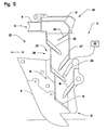
- the seed counting device (22) is advantageously placed at least partially in an implantation member (8).
- said guiding elements (25) of the seed alignment device (23) are here at least partially constituted by said drops (15) of at least one of said regulating devices (14).
- This fourth example therefore makes it possible to reduce in particular the added height of the seed counting device (22) and the regulating device (14). It is designed to be mounted on a pneumatic seeder.
- the flow of seeds also arrives transversely to evacuate the flow of air through the grid (21).
- at least one guide element (25) and one grouping ramp (26) are added to the drops (15). This makes it possible to arrange the seed counter (24) on the first chute (15), the seeds being already aligned at this stage.
- Another advantage of the implantation of the seed counter in the cassette (28) is to protect it from external aggression due mainly to the land that can be projected.
- At least one seed counting device (22) is implanted on one of the pipes (9). This advantageously makes it possible to continuously control and / or modify, during the sowing operation, the number of seeds to be sown, the dose modulation being able for example to be controlled from GPS or DGPS data.
- the drill (1) comprises a "2-way” valve mounted between the supply column (16) and a respective metering member of a dispensing head (17). Said "2-way” valve allowing in one position the conveyance of seeds leaving said metering member to said feed column (16) and in the other position, the conveying seeds from said dosing member to the seed counting device (22). This valve being controlled by the terminal (33).
- This exemplary embodiment therefore only makes it possible to count the seeds before starting the sowing operation and / or during maneuvers at the headland, since the seeds are either directed towards the distribution head (17) to be sown, or to the seed counter (24) to be counted. Continuous control of the number of seeds during the sowing operation is therefore not possible, but this procedure can often be sufficient to correctly adjust the metering device (7).
Description
La présente invention se rapporte au domaine technique général du machinisme agricole et en particulier aux machines de distribution. Elle concerne plus particulièrement un semoir selon la revendication 1.The present invention relates to the general technical field of agricultural machinery and in particular to dispensing machines. It relates more particularly to a drill according to claim 1.
Un tel semoir est connu dans le tirage spécial de Lemken ayant pour titre « Körner pro Quadratmeter statt Kilogramm pro Hektar ». Ce semoir comporte d'une manière connue en soi une trémie, un dispositif de dosage, une tête de distribution alimentée à partir du dispositif de dosage au moyen d'un tuyau, plusieurs organes d'implantation de graines dans le sol et des tuyaux raccordant la tête de distribution aux organes d'implantation. Ce semoir comporte en sus un dispositif de comptage de graines composé d'un dispositif d'alignement et d'un compteur de graines. Le dispositif de comptage de graines comporte, en sus, un dispositif de séparation des graines du flux d'air. Ce dispositif de séparation est constitué par un cyclone. Le cyclone comporte à sa partie supérieure un orifice par lequel s'échappe l'air. Il est prolongé vers le bas par une tubulure à travers laquelle les graines tombent par gravité dans un récipient. Les graines contenues dans ce récipient sont alors alignées au moyen du dispositif d'alignement. En sortie du dispositif d'alignement, les graines sont comptées par le compteur de graines réalisé par une cellule photoélectrique. Le compteur de graines transmet le nombre de graines à un terminal qui compare ce nombre avec le nombre de graines à semer. Le terminal pilote aussi le dispositif de dosage. Les graines comptées sont ensuite réinjectées dans la trémie.Such a drill is known in Lemken's special edition entitled " Körner pro Quadratmeter Statt Kilogram Pro Hektar ". This seed drill comprises in a manner known per se a hopper, a metering device, a dispensing head fed from the metering device by means of a pipe, a plurality of seed implantation members into the ground and connecting pipes. the dispensing head to the implantation members. This seed drill additionally comprises a seed counting device consisting of an alignment device and a seed counter. The seed counting device additionally comprises a device for separating the seeds from the air flow. This separation device is constituted by a cyclone. The cyclone has at its upper part an orifice through which the air escapes. It is extended downwards by a tubing through which the seeds fall by gravity into a container. The seeds contained in this container are then aligned by means of the alignment device. At the output of the alignment device, the seeds are counted by the seed counter produced by a photocell. The seed counter transmits the number of seeds to a terminal which compares this number with the number of seeds to be sown. The terminal also controls the dosing device. The counted seeds are then reinjected into the hopper.
Le dispositif d'alignement est composé de deux rouleaux. Ces rouleaux sont entraînés en rotation afin d'individualiser les graines à compter. Les graines tombent du récipient sur ces deux rouleaux entraînés en rotation et sont ainsi alignées pour être recensées par la cellule photoélectrique. L'espace entre les deux rouleaux est adaptable à la taille des graines. La réalisation de ce dispositif d'alignement est complexe, notamment parce qu'il existe un mécanisme d'entraînement des deux rouleaux.The alignment device consists of two rollers. These rollers are rotated to individualize the seeds to count. The seeds fall from the container on these two rollers driven in rotation and are thus aligned to be recorded by the photocell. The space between the two rolls is adaptable to the size of the seeds. The realization of this alignment device is complex, especially because there is a drive mechanism of the two rollers.
Le document
Pour le fonctionnement de ce dispositif de comptage de graines, il faut d'une part entraîner le disque à trous en rotation et d'autre part installer une aspiration sous le disque à trous pour que les graines soient aspirées sur les trous afin d'être comptées. Le disque comporte encore un sélecteur de graines et un éjecteur de graines. Les trous des disques doivent être adaptés aux différents types de graines à compter. La réalisation de ce dispositif de comptage de graines est également compliquée.For the operation of this seed counting device, it is necessary firstly to drive the disk with holes in rotation and secondly to install a suction under the disk with holes so that the seeds are sucked on the holes to be counted. The disc still has a seed selector and a seed ejector. The holes of the discs must be adapted to the different types of seeds to be counted. The realization of this seed counting device is also complicated.
On connaît également le semoir du type monograine décrit dans le document
Le document
L'obtention du nombre exact de graines, lorsqu'elles sont transportées par un flux d'air jusqu'aux organes d'implantation, nécessite l'emploi de moyens de haute résolution pour obtenir un résultat fiable. Il est tout à fait possible avec un débit de graines élevé que plusieurs graines passent en même temps devant le compteur de graines et qu'une seule soit comptée. Un tel compteur de graines n'est donc pas très précis et est en sus relativement coûteux.Obtaining the exact number of seeds, when transported by a flow of air to the implantation organs, requires the use of high resolution means to obtain a reliable result. It is quite possible with a high seed rate that several seeds pass at the same time in front of the seed counter and only one is counted. Such a seed counter is therefore not very accurate and is in addition relatively expensive.
Un autre système décrit dans la brochure
Le comptage des graines dans le tuyau d'acheminement lorsqu'elles sont transportées par le flux d'air n'est pas très fiable non plus.The counting of seeds in the transport pipe when transported by the airflow is not very reliable either.
Il est encore connu par le document
La présente invention a pour but de remédier aux inconvénients précités. Elle doit notamment proposer un dispositif de comptage de graines simple, économique et facilement utilisable pour toutes sortes de graines habituellement semées par les agriculteurs, tout en garantissant une bonne précision.The present invention aims to overcome the aforementioned drawbacks. It must in particular provide a simple, economical and easily used seed counting device for all kinds of seeds usually sown by farmers, while ensuring good accuracy.
A cet effet, une importante caractéristique de l'invention consiste en ce que ledit dispositif d'alignement des graines à compter est constitué par une suite d'éléments de guidage inclinés l'un vers son suivant et sur lesquels glissent lesdites graines à compter.For this purpose, an important characteristic of the invention consists in that said device for aligning the seeds to be counted consists of a succession of guide elements inclined one towards its next and on which said seeds slide to count.
D'autres caractéristiques et avantages de l'invention ressortiront de la description qui va suivre et qui se réfère aux dessins annexés qui représentent, à titre d'exemples non limitatifs, quelques formes de réalisation de l'invention. Dans ces dessins :
- la
figure 1 représente une vue latérale d'un semoir comportant un dispositif de comptage de graines conforme à l'invention, - la
figure 2 représente, à plus grande échelle, un exemple de réalisation d'un dispositif de comptage de graines disposé sur un tuyau raccordant indirectement ledit dispositif de dosage à un organe d'implantation de graines dans le sol, - la
figure 3 représente selon un autre exemple de réalisation dans lequel un dispositif de comptage de graines est disposé sur un tuyau raccordant ledit dispositif de dosage à un organe d'implantation de graines dans le sol, - la
figure 4 représente selon un autre exemple de réalisation dans lequel un dispositif de comptage de graines est disposé directement en amont d'un organe d'implantation de graines dans le sol, et - la
figure 5 représente selon un autre exemple de réalisation dans lequel un dispositif de comptage de graines est disposé au moins partiellement dans un organe d'implantation de graines dans le sol.
- the
figure 1 represents a side view of a seed drill comprising a seed counting device according to the invention, - the
figure 2 represents, on a larger scale, an exemplary embodiment of a seed counting device disposed on a connecting pipe indirectly said dosing device to a seed implantation member in the soil, - the
figure 3 represents according to another embodiment in which a seed counting device is arranged on a pipe connecting said metering device to a member for planting seeds in the soil, - the
figure 4 represents according to another exemplary embodiment in which a seed counting device is disposed directly upstream of a seed implantation member in the soil, and - the
figure 5 represents according to another embodiment wherein a seed counting device is disposed at least partially in a seed implantation member in the soil.
La machine agricole de travail du sol représentée sur les figures comprend notamment un semoir (1). Il s'agit plus précisément d'un semoir du type en lignes comme représenté à la
Ce semoir (1) peut également être directement attelé à un tracteur (2). Cet exemple de réalisation n'est pas représenté sur les figures.This seed drill (1) can also be directly coupled to a tractor (2). This exemplary embodiment is not shown in the figures.
Le semoir (1) de la
Chaque organe d'implantation (8) est formé par un corps creux en forme de tube de section rectangulaire. Sa face avant et sa base comportent une pièce effilée (11) de manière à pouvoir ouvrir une petite tranchée dans la terre. La partie supérieure de chaque organe d'implantation (8) possède un orifice d'entrée (12) qui est relié à un tuyau (9) et par lequel arrivent les graines. La partie inférieure de chaque organe d'implantation (8) possède un orifice de sortie (13) par lequel lesdites graines sont implantées dans le sol. L'organe d'implantation (8) comporte dans cette réalisation, mais de manière non limitative, un dispositif de régulation (14) qui assure un espacement sensiblement constant entre les graines sortant de l'orifice de sortie (13). Ce dispositif de régulation (14) est disposé dans le corps. Il comporte des chutes (15) inclinées l'une vers sa suivante depuis l'orifice d'entrée (12) jusqu'à l'orifice de sortie (13). Lesdites chutes (15) sont disposées avantageusement en zigzag.Each implantation member (8) is formed by a hollow body in the form of a tube of rectangular section. Its front face and its base comprise a tapered part (11) so as to open a small trench in the ground. The upper part of each implantation member (8) has an inlet (12) which is connected to a pipe (9) and through which the seeds arrive. The lower part of each implantation member (8) has an outlet (13) through which said seeds are implanted in the soil. The implantation member (8) comprises in this embodiment, but in a nonlimiting manner, a regulating device (14) which ensures a substantially constant spacing between the seeds leaving the outlet orifice (13). This regulating device (14) is arranged in the body. It comprises drops (15) inclined one towards its next from the inlet (12) to the outlet (13). Said falls (15) are advantageously arranged in zigzag.
Les graines qui arrivent par le tuyau (9) glissent, sous l'effet de leur propre poids, sur lesdites chutes (15) en vue d'obtenir une régularité de dépose desdites graines dans le sillon dans le sens longitudinal, c'est-à-dire selon la direction d'avance (4), et en profondeur. Le dispositif de régulation (14) est avantageusement interchangeable, ce qui permet de l'adapter aux familles de graines à semer. Un tel dispositif de régulation (14) est connu de l'homme du métier et ne sera donc pas décrit plus en détail.The seeds which arrive by the pipe (9) slide, under the effect of their own weight, on said falls (15) in order to obtain a regularity of deposit of said seeds in the groove in the longitudinal direction, that is to say to say in the direction of advance (4), and in depth. The regulating device (14) is advantageously interchangeable, which makes it possible to adapt it to the families of seeds to be sown. Such a regulating device (14) is known to those skilled in the art and will therefore not be described in more detail.
Dans l'exemple de réalisation de la
Chaque organe d'implantation (8) comporte en sus, après l'orifice d'entrée (12) et la première chute (15), un dispositif de séparation (20) desdites graines du flux d'air les transportant. Ce dispositif de séparation (20) est par exemple une grille (21) au travers de laquelle s'échappe ledit flux d'air. Cette grille (21) présente des mailles dont les dimensions sont inférieures à celles des graines de sorte que ces dernières soient retenues à l'intérieur de l'organe d'implantation (8). Ladite grille (21) est située sensiblement dans le prolongement dudit orifice d'entrée (12). Ainsi le flux d'air s'échappe et les graines tombent dans le dispositif de régulation (14).Each implantation member (8) further comprises, after the inlet port (12) and the first chute (15), a separating device (20) of said seeds of the airflow carrying them. This separation device (20) is for example a grid (21) through which said air flow escapes. This grid (21) has meshes whose dimensions are smaller than those of the seeds so that the latter are retained inside the implant member (8). Said gate (21) is located substantially in the extension of said inlet port (12). Thus the air flow escapes and the seeds fall into the regulating device (14).
Le semoir (1) selon l'invention comporte un dispositif de comptage de graines (22). Ce dernier est représenté schématiquement avec un cadre en traits mixtes sur la
Selon une importante caractéristique de la présente invention, le dispositif d'alignement (23) des graines à compter est constitué par une suite d'éléments de guidage (25) inclinés l'un vers son suivant et sur lesquels glissent les graines à compter de manière à les aligner. D'une manière avantageuse, deux éléments de guidage (25) consécutifs forment entre eux un angle (alpha) compris entre 60° et 100°. Il varie en fonction du type de graines à semer. Pour aligner les graines, on utilise au moins trois éléments de guidage (25) consécutifs. D'autre part pour un meilleur fonctionnement, une rampe de regroupement (26) est disposée en amont du premier élément de guidage (25). Sa fonction est de réceptionner les graines qui arrivent par le tuyau (9) et d'assurer qu'elles tombent en tête du premier élément de guidage (25). Cette rampe de regroupement (26) présente une section transversale plane.According to an important feature of the present invention, the alignment device (23) for the seeds to be counted consists of a series of guide elements (25) inclined one towards its next and on which the seeds slide from to align them. Advantageously, two consecutive guide elements (25) form between them an angle (alpha) of between 60 ° and 100 °. It varies according to the type of seeds to be sown. To align the seeds, at least three consecutive guide elements (25) are used. On the other hand for better operation, a grouping ramp (26) is arranged upstream the first guide element (25). Its function is to receive the seeds that arrive through the pipe (9) and to ensure that they fall at the top of the first guide element (25). This grouping ramp (26) has a flat cross section.
Les éléments de guidage (25) présentent, quant à eux, avantageusement une forme de gouttières permettant le guidage des graines. Les graines glissent donc d'un élément de guidage (25) vers l'autre pour être alignées en sortie du dernier élément de guidage (25). Lesdites gouttières présentent un profil en V avec un angle d'ouverture (bêta) compris entre 50° et 70°. Un angle d'ouverture (bêta) de 60° donne de très bon résultat de guidage des graines. Le guidage des petites graines est amélioré lorsque les éléments de guidage (25) ont une section transversale en forme de V avec un fond arrondi. Il est important qu'au moins le dernier élément de guidage (25) présente une forme de gouttière.The guide elements (25) have, for their part, advantageously a shape of gutters for guiding the seeds. The seeds thus slide from one guide element (25) towards the other to be aligned at the outlet of the last guide element (25). Said gutters have a V-shaped profile with an opening angle (beta) of between 50 ° and 70 °. An opening angle (beta) of 60 ° gives a very good result of guiding seeds. The guiding of the small seeds is improved when the guide elements (25) have a V-shaped cross section with a rounded bottom. It is important that at least the last guide member (25) has a gutter shape.
Comme cela est représenté sur les
La cassette (28) représentée à la
La cassette (28) représentée à la
Dans l'exemple de réalisation des
La
Pour éviter une perturbation de l'écoulement des graines dans le dispositif d'alignement (23), il est avantageux de séparer le flux de graines à compter du flux d'air véhiculant les graines par l'intermédiaire d'un dispositif de séparation du flux d'air (29). Le dispositif de séparation du flux d'air (29) est réalisé par un cyclone (29'). Ce cyclone (29') se situe en amont du dispositif d'alignement (23). Le tuyau (9) avec les graines véhiculées par le flux d'air débouche tangentiellement dans ledit cyclone (29'). Il comporte dans sa partie supérieure un orifice (30) par lequel s'échappe le flux d'air. Le cyclone (29') est prolongé vers le bas par une tubulure (31) à travers laquelle les graines tombent par gravité dans ledit dispositif d'alignement (23). Les graines sont comptées à la sortie via le compteur de graines (24). En aval du dispositif de comptage de graines (22), on récupère les graines via un entonnoir (34) et on injecte à nouveau un flux d'air dans le flux de graines comptées au moyen d'un dispositif d'injection d'air (32). Les graines sont alors transportées jusqu'à l'organe d'implantation (8) correspondant pour être implantées dans la terre. Les graines à compter peuvent être véhiculées par un flux d'air produit par un générateur (180) séparé. Le dispositif d'injection d'air (32) est lié directement audit générateur (180). Mais ce générateur (180) produisant un flux d'air destiné à véhiculer les graines à compter ou les graines déjà comptées peut avantageusement être constitué directement par le générateur (18) produisant un flux d'air destiné à véhiculer les graines à semer. L'alignement des graines en sortie de cassette (28) est optimal pour le compteur de graines (24). Ce dernier transmet le nombre de graines compté à un terminal (33). Il compare le nombre de graines qui a été compté à un nombre de graines à semer par mètre carré par exemple. Le terminal (33) permet également de régler automatiquement, le cas échéant, le dispositif de dosage (7) pour modifier le nombre de graines semées. Le terminal (33) est placé dans la cabine du tracteur (2). Le compteur de graines (24) est réalisé par exemple par une cellule photoélectrique. Il est réalisé en général par un capteur disponible dans le commerce.To avoid a disturbance of the flow of seeds in the alignment device (23), it is advantageous to separate the flow of seeds from the flow of air conveying the seeds by means of a separation device of the air flow (29). The airflow separation device (29) is made by a cyclone (29 '). This cyclone (29 ') is located upstream of the alignment device (23). The pipe (9) with the seeds conveyed by the air flow opens tangentially into said cyclone (29 '). It comprises in its upper part an orifice (30) through which escapes the air flow. The cyclone (29 ') is extended downwardly by a pipe (31) through which the seeds fall by gravity into said alignment device (23). The seeds are counted at the exit via the seed counter (24). Downstream of the seed counting device (22), the seeds are recovered via a funnel (34) and a flow of air is injected into the counted seed stream by means of an air injection device. (32). The seeds are then transported to the corresponding implantation member (8) to be implanted in the soil. The seeds to be counted can be conveyed by a flow of air produced by a separate generator (180). The air injection device (32) is directly connected to said generator (180). But this generator (180) producing a flow of air for conveying the seeds to count or seeds already counted can advantageously be constituted directly by the generator (18) producing a flow of air for conveying the seeds to be sown. The seed alignment at the cassette outlet (28) is optimal for the seed counter (24). The latter transmits the number of seeds counted to a terminal (33). He compares the number of seeds that has been counted to a number of seeds to be sown per square meter for example. The terminal (33) can also automatically adjust, if necessary, the metering device (7) to change the number of seed sown. The terminal (33) is placed in the tractor cab (2). The seed counter (24) is made for example by a photocell. It is generally performed by a commercially available sensor.
Une autre solution pour réinjecter un flux d'air dans le tuyau (9) amenant les graines dans le sol est d'utiliser le flux d'air séparé par le dispositif de séparation (29) pour le réinjecter dans le flux de graines comptées en aval du compteur de graines (24). Un dispositif de réinjection du flux d'air séparé est donc prévu en aval du compteur de graines (24). Cet exemple de réalisation n'est pas représenté sur les figures.Another solution for reinjecting a flow of air into the pipe (9) bringing the seeds into the soil is to use the air flow separated by the separating device (29) to reinject it into the stream of seeds counted as downstream of the seed counter (24). A device for reinjecting the separated air flow is therefore provided downstream of the seed counter (24). This exemplary embodiment is not shown in the figures.
D'autre part, le compteur de graines pourrait très bien être fonctionnel même si le flux de graines à compter n'est pas séparé du flux d'air, car le flux d'air ne perturbe pas vraiment l'alignement des graines, mais plutôt l'espacement entre deux graines successives ce qui n'a pas vraiment une incidence sur le comptage.On the other hand, the seed counter could very well be functional even if the flow of seeds to be counted is not separated from the air flow, because the airflow does not really disturb the alignment of the seeds, but rather the spacing between two successive seeds which does not really affect the count.
Dans l'exemple de réalisation de la
Selon un troisième exemple de réalisation représenté à la
Cette troisième réalisation est simple car elle ne nécessite pas de réinjection d'air dans un tuyau (9). Par ailleurs le dispositif de comptage de graines (22) est ainsi placé relativement proche du sol et a donc une influence moindre sur l'opération de semis.This third embodiment is simple because it does not require reinjection of air into a pipe (9). In addition, the seed counting device (22) is thus placed relatively close to the ground and therefore has a lesser influence on the sowing operation.
D'après un quatrième exemple de réalisation représenté à la
Pour les quatre exemples de réalisation décrits ci-avant, on implante au moins un dispositif de comptage de graines (22) sur l'un des tuyaux (9). Ceci permet avantageusement de contrôler en continu et/ou de modifier, pendant l'opération de semis le nombre de graines à semer, la modulation de dose pouvant par exemple être commandée à partir de données GPS ou DGPS.For the four embodiments described above, at least one seed counting device (22) is implanted on one of the pipes (9). This advantageously makes it possible to continuously control and / or modify, during the sowing operation, the number of seeds to be sown, the dose modulation being able for example to be controlled from GPS or DGPS data.
Selon un autre exemple de réalisation non représenté, le semoir (1) comporte une vanne « 2 voies » montée entre la colonne d'alimentation (16) et un organe de dosage respectif d'une tête de distribution (17). Ladite vanne « 2 voies » permettant dans une position le véhiculage des graines sortant dudit organe de dosage vers ladite colonne d'alimentation (16) et dans l'autre position, le véhiculage des graines dudit organe de dosage vers le dispositif de comptage de graines (22). Cette vanne étant commandée par le terminal (33). Cet exemple de réalisation permet donc uniquement de compter les graines avant de débuter l'opération de semis et/ou pendant les manoeuvres en bout de champ, car les graines sont soit dirigées vers la tête de distribution (17) pour être semées, soit vers le compteur de graines (24) pour être comptées. Un contrôle continu du nombre de graines durant l'opération de semis n'est donc pas possible mais cette procédure peut souvent être suffisante pour régler correctement le dispositif de dosage (7).According to another embodiment not shown, the drill (1) comprises a "2-way" valve mounted between the supply column (16) and a respective metering member of a dispensing head (17). Said "2-way" valve allowing in one position the conveyance of seeds leaving said metering member to said feed column (16) and in the other position, the conveying seeds from said dosing member to the seed counting device (22). This valve being controlled by the terminal (33). This exemplary embodiment therefore only makes it possible to count the seeds before starting the sowing operation and / or during maneuvers at the headland, since the seeds are either directed towards the distribution head (17) to be sown, or to the seed counter (24) to be counted. Continuous control of the number of seeds during the sowing operation is therefore not possible, but this procedure can often be sufficient to correctly adjust the metering device (7).
Il est bien évident que l'invention n'est pas limitée aux modes de réalisation décrits ci-dessus et représentés sur les dessins annexés. Des modifications restent possibles, notamment en ce qui concerne la constitution ou le nombre des divers éléments ou par substitution d'équivalents techniques, sans pour autant sortir du domaine de protection défini par les revendications.It is obvious that the invention is not limited to the embodiments described above and shown in the accompanying drawings. Modifications remain possible, in particular as regards the constitution or the number of the various elements or by substitution of technical equivalents, without departing from the scope of protection defined by the claims.
Claims (24)
- Seeder (1) comprising among other things:- a hopper (6) containing seeds to be sown;- a metering device (7) allowing the quantity of seeds deposited in the soil to be adjusted;- at least one planting element (8) for seeds in the soil;- a pipe (9) connecting directly or indirectly the said metering device (7) to the respective planting element (8); and- a seed counting device (22) including in particular an alignment device (23) for the seeds which are to be counted, and a seed counter (24) arranged downstream of the said alignment device (23) for the seeds which are to be counted,
characterized in that the said alignment device (23) for the seeds which are to be counted is constituted by a series of guiding elements (25), inclined one towards the next, and on which the said seeds which are to be counted slide. - Seeder according to Claim 1, characterized in that two consecutive guiding elements (25) form between them an angle (alpha) comprised between 60° and 100°.
- Seeder according to claim 1 or 2, characterized in that the number of guiding elements (25) is at least 3.
- Seeder according to any one of Claims 1 to 3, characterized in that at least the last guiding element (25) before the said seed counter (24) is achieved in the form of a gutter.
- Seeder according to Claim 4, characterized in that all the guiding elements (25) are achieved in the form of a gutter.
- Seeder according to Claim 4 or 5, characterized in that the said gutter has a V-shaped profile with an angle (beta) comprised between 50° and 70°.
- Seeder according to Claim 6, characterized in that the base of the V-shaped profile is rounded.
- Seeder according to any one of Claims 1 to 7, characterized in that the said guiding elements (25) are grouped together in a single piece (27).
- Seeder according to Claim 8, characterized in that the said single piece (27) grouping together the guiding elements (25) is a box (28).
- Seeder according to Claim 8 or 9, characterized in that the said single piece (27) grouping together the guiding elements (25) is removable.
- Seeder according to any one of Claims 1 to 5, characterized in that the said seed counting device (22) is provided on one of the pipes (9).
- Seeder according to Claim 6, characterized in that the seed counting device (22) is provided directly upstream of the respective planting element (8).
- Seeder according to any one of Claims 1 to 5, characterized in that the seed counting device (22) is provided directly in one at least of the planting elements (8).
- Seeder according to Claim 13, characterized in that the planting elements (8) each comprise, in a manner known per se, chutes (15) inclined one towards the next and on which the seeds which are to be deposited in the soil slide, in order to obtain a regularity of depositing of the said seeds in the furrow, as well in the longitudinal direction as in depth, and that the said guiding elements (25) of the alignment device (23) for the seeds which are to be counted are arranged upstream of the said chutes (15) of one at least of the said planting elements (8).
- Seeder according to Claim 13, characterized in that the planting elements (8) each comprise, in a manner known per se, chutes (15) inclined one towards the next and on which the seeds which are to be deposited in the soil slide, in order to obtain a regularity of depositing of the said seeds in the furrow, as well in the longitudinal direction as in depth, and that the said guiding elements (25) of the alignment device (23) of the seeds which are to be counted are at least partially constituted by the said chutes (15) of one at least of the said planting elements (8).
- Seeder according to any one of Claims 1 to 9, characterized in that the seed counter (24) is a commercially available counter.
- Seeder according to any one of Claims 1 to 8, characterized in that in addition a terminal (33) is provided, which compares the number of seeds which have been counted with a number of seeds which are to be sown, and which automatically adjusts the metering device (7) if applicable.
- Seeder according to any one of Claims 1 to 17, characterized in that a generator (180) is provided, generating a flow of air intended to convey the seeds which are to be counted, and in that in addition, upstream of the series of guiding elements (25), an air flow separation device (20) is provided, separating the flow of air from the flow of seeds which are to be counted.
- Seeder according to Claim 18, characterized in that, downstream of the seed counter (24), a device is provided for the reinjection of the separated air flow, which is intended to reinject the separated air flow in the flow of counted seeds.
- Seeder according to Claim 18, characterized in that, downstream of the seed counter (24), an air injection device (32) is provided, intended to inject air in the flow of counted seeds.
- Seeder according to any one of Claims 18 to 20, characterized in that the said seeder (1) is a pneumatic seeder comprising in addition, in a manner known per se, a generator (18) generating a flow of air intended to convey the seeds which are to be sown, and at least one distribution head (17) supplied by a respective metering element of the metering device (7) through a corresponding supply column (16).
- Seeder according to Claim 18, characterized in that the generator (180) generating a flow of air intended to convey the seeds which are to be counted is constituted by the generator (18) generating a flow of air intended to convey the seeds which are to be sown.
- Seeder according to Claim 21 or 22, characterized in that between the respective supply column (16) and the metering element of a distribution head (17) a "two-way" valve is provided, allowing in one position the conveying of the seeds coming out from the said metering element towards the said supply column (16) and, in the other position, the conveying of the seeds of the said metering element towards the seed counting device (22).
- Seeder according to Claim 23 and Claim 17, characterized in that the guiding of the said "two-way" valve is controlled by the said terminal (33).
Applications Claiming Priority (2)
| Application Number | Priority Date | Filing Date | Title |
|---|---|---|---|
| FR0314312A FR2863142B1 (en) | 2003-12-05 | 2003-12-05 | SEMOIR EQUIPPED WITH A SEED COUNTING SYSTEM |
| FR0314312 | 2003-12-05 |
Publications (2)
| Publication Number | Publication Date |
|---|---|
| EP1537768A1 EP1537768A1 (en) | 2005-06-08 |
| EP1537768B1 true EP1537768B1 (en) | 2013-03-13 |
Family
ID=34451731
Family Applications (1)
| Application Number | Title | Priority Date | Filing Date |
|---|---|---|---|
| EP20040300829 Expired - Fee Related EP1537768B1 (en) | 2003-12-05 | 2004-12-01 | Seeder equiped with a seed counter device |
Country Status (2)
| Country | Link |
|---|---|
| EP (1) | EP1537768B1 (en) |
| FR (1) | FR2863142B1 (en) |
Families Citing this family (6)
| Publication number | Priority date | Publication date | Assignee | Title |
|---|---|---|---|---|
| DE102006038865A1 (en) * | 2006-08-18 | 2008-02-21 | Alois Pöttinger Maschinenfabrik Gmbh | Sowing machine and method for controlling the discharge of a drill |
| EP2827698B1 (en) | 2012-03-22 | 2016-03-09 | Bayer Intellectual Property GmbH | Seeding machine and seeding method |
| CA2904781C (en) | 2014-11-04 | 2022-04-19 | Cnh Industrial Canada, Ltd. | Quick release bearing couplers |
| CA3058721C (en) | 2014-11-04 | 2021-05-11 | Cnh Industrial Canada, Ltd. | Modular meter roller cartridge |
| CA2904789C (en) | 2014-11-04 | 2020-03-31 | Cnh Industrial Canada, Ltd. | Split meter roller shaft |
| US9801330B2 (en) | 2015-11-04 | 2017-10-31 | Cnh Industrial Canada, Ltd. | Meter roller cartridge frame for an agricultural metering system |
Family Cites Families (7)
| Publication number | Priority date | Publication date | Assignee | Title |
|---|---|---|---|---|
| DE62541C (en) * | J. BERTOLDI in Neubrandenburg i. M | Seed tubes for seed drills | ||
| GB2082006B (en) * | 1980-08-08 | 1984-07-25 | Dickey John Corp | Seed planter |
| DE3535871A1 (en) | 1985-10-08 | 1987-04-09 | Andreas Reichhardt | Metering apparatus for granular bulk material |
| DE19636787C1 (en) * | 1996-09-11 | 1998-04-02 | Univ Hohenheim | Leveling device for metering granules, in particular for use in a seed drill |
| DE10037713A1 (en) | 2000-08-02 | 2002-02-21 | Lemken Gmbh & Co Kg | Pneumatic drilling machine for sowing seed has on board computer which counts seed passing through one distribution channel and calculates overall seed per square meter |
| DE10134991B4 (en) | 2001-07-18 | 2013-08-14 | Lemken Gmbh & Co. Kg | Seed drill with automatic calibration |
| FR2836737B1 (en) * | 2002-03-01 | 2004-06-18 | Centre Nat Machinisme Agricole | DEVICE FOR COUNTING PARTICLES SUCH AS SEEDS DISTRIBUTED BY A SEEDER |
-
2003
- 2003-12-05 FR FR0314312A patent/FR2863142B1/en not_active Expired - Fee Related
-
2004
- 2004-12-01 EP EP20040300829 patent/EP1537768B1/en not_active Expired - Fee Related
Also Published As
| Publication number | Publication date |
|---|---|
| EP1537768A1 (en) | 2005-06-08 |
| FR2863142B1 (en) | 2006-03-17 |
| FR2863142A1 (en) | 2005-06-10 |
Similar Documents
| Publication | Publication Date | Title |
|---|---|---|
| US11849665B2 (en) | Seeding machine with seed delivery system | |
| US11558996B2 (en) | Planter with seed delivery apparatus | |
| EP2854499B1 (en) | Single grain seeder and seed singulation disc with open grooves | |
| US20170049040A1 (en) | Planter with seed delivery apparatus | |
| EP0598636B1 (en) | Precision seeddrill | |
| EP2696668B1 (en) | Remote feeding device for a single-grain seed drill and single-grain seed drill using such a feeding device | |
| EP2931019B1 (en) | Device for a self-regulated pneumatic supply with a means for regulating the air passage section | |
| EP2953443B1 (en) | Single-grain seeder with at least one improved seeding element | |
| EP3238519B1 (en) | Device for controlling seed distribution for seeder, and corresponding seeder | |
| EP1537768B1 (en) | Seeder equiped with a seed counter device | |
| FR2531603A1 (en) | POWDER SEEDER | |
| EP3238518A1 (en) | Seeder provided with a device for controlling the distribution of seeds, and corresponding control device | |
| CA2342125A1 (en) | Device for introducing seeds into the soil and seeding equipment equipped with such devices | |
| EP2672804A1 (en) | Distribution box for single-seed drill having stirring blades, and seed drill using such a box | |
| EP1430761B1 (en) | Metering device for a seed drill which can spread different products simultaneously | |
| EP1488674B1 (en) | Pneumatic seed distributor | |
| EP3476192B1 (en) | Device for controlling seed distribution for seeder, and corresponding seeder | |
| WO2024052791A1 (en) | Air entrainment seed accelerator | |
| EP3031312A1 (en) | Seed meter for seed planter having a pressurized compartment | |
| BE543355A (en) | ||
| BR132015013585E2 (en) | A sowing machine for a ramp unit, and a method for dispensing a seed of a seeder for a subsoil | |
| BE528440A (en) |
Legal Events
| Date | Code | Title | Description |
|---|---|---|---|
| PUAI | Public reference made under article 153(3) epc to a published international application that has entered the european phase |
Free format text: ORIGINAL CODE: 0009012 |
|
| AK | Designated contracting states |
Kind code of ref document: A1 Designated state(s): AT BE BG CH CY CZ DE DK EE ES FI FR GB GR HU IE IS IT LI LT LU MC NL PL PT RO SE SI SK TR |
|
| AX | Request for extension of the european patent |
Extension state: AL BA HR LV MK YU |
|
| 17P | Request for examination filed |
Effective date: 20051129 |
|
| AKX | Designation fees paid |
Designated state(s): DE DK FR IT |
|
| 17Q | First examination report despatched |
Effective date: 20060207 |
|
| GRAP | Despatch of communication of intention to grant a patent |
Free format text: ORIGINAL CODE: EPIDOSNIGR1 |
|
| GRAP | Despatch of communication of intention to grant a patent |
Free format text: ORIGINAL CODE: EPIDOSNIGR1 |
|
| GRAS | Grant fee paid |
Free format text: ORIGINAL CODE: EPIDOSNIGR3 |
|
| GRAA | (expected) grant |
Free format text: ORIGINAL CODE: 0009210 |
|
| AK | Designated contracting states |
Kind code of ref document: B1 Designated state(s): DE DK FR IT |
|
| REG | Reference to a national code |
Ref country code: DE Ref legal event code: R096 Ref document number: 602004041320 Country of ref document: DE Effective date: 20130508 |
|
| PLBE | No opposition filed within time limit |
Free format text: ORIGINAL CODE: 0009261 |
|
| STAA | Information on the status of an ep patent application or granted ep patent |
Free format text: STATUS: NO OPPOSITION FILED WITHIN TIME LIMIT |
|
| PG25 | Lapsed in a contracting state [announced via postgrant information from national office to epo] |
Ref country code: DK Free format text: LAPSE BECAUSE OF FAILURE TO SUBMIT A TRANSLATION OF THE DESCRIPTION OR TO PAY THE FEE WITHIN THE PRESCRIBED TIME-LIMIT Effective date: 20130313 |
|
| 26N | No opposition filed |
Effective date: 20131216 |
|
| PG25 | Lapsed in a contracting state [announced via postgrant information from national office to epo] |
Ref country code: IT Free format text: LAPSE BECAUSE OF FAILURE TO SUBMIT A TRANSLATION OF THE DESCRIPTION OR TO PAY THE FEE WITHIN THE PRESCRIBED TIME-LIMIT Effective date: 20130313 |
|
| REG | Reference to a national code |
Ref country code: DE Ref legal event code: R097 Ref document number: 602004041320 Country of ref document: DE Effective date: 20131216 |
|
| REG | Reference to a national code |
Ref country code: FR Ref legal event code: PLFP Year of fee payment: 12 |
|
| REG | Reference to a national code |
Ref country code: FR Ref legal event code: PLFP Year of fee payment: 13 |
|
| REG | Reference to a national code |
Ref country code: FR Ref legal event code: PLFP Year of fee payment: 14 |
|
| PGFP | Annual fee paid to national office [announced via postgrant information from national office to epo] |
Ref country code: FR Payment date: 20181226 Year of fee payment: 15 |
|
| PGFP | Annual fee paid to national office [announced via postgrant information from national office to epo] |
Ref country code: DE Payment date: 20181231 Year of fee payment: 15 |
|
| REG | Reference to a national code |
Ref country code: DE Ref legal event code: R119 Ref document number: 602004041320 Country of ref document: DE |
|
| PG25 | Lapsed in a contracting state [announced via postgrant information from national office to epo] |
Ref country code: FR Free format text: LAPSE BECAUSE OF NON-PAYMENT OF DUE FEES Effective date: 20191231 Ref country code: DE Free format text: LAPSE BECAUSE OF NON-PAYMENT OF DUE FEES Effective date: 20200701 |