EP1536960B1 - Antriebseinheit für einen kraftfahrzeugachsstabilisator - Google Patents
Antriebseinheit für einen kraftfahrzeugachsstabilisator Download PDFInfo
- Publication number
- EP1536960B1 EP1536960B1 EP03756437A EP03756437A EP1536960B1 EP 1536960 B1 EP1536960 B1 EP 1536960B1 EP 03756437 A EP03756437 A EP 03756437A EP 03756437 A EP03756437 A EP 03756437A EP 1536960 B1 EP1536960 B1 EP 1536960B1
- Authority
- EP
- European Patent Office
- Prior art keywords
- drive unit
- piston
- housing
- halves
- releasing
- Prior art date
- Legal status (The legal status is an assumption and is not a legal conclusion. Google has not performed a legal analysis and makes no representation as to the accuracy of the status listed.)
- Expired - Lifetime
Links
- 239000003381 stabilizer Substances 0.000 title claims abstract description 29
- 238000006073 displacement reaction Methods 0.000 claims abstract description 12
- 230000000717 retained effect Effects 0.000 claims 1
- 230000007935 neutral effect Effects 0.000 description 5
- 238000005192 partition Methods 0.000 description 3
- 230000001133 acceleration Effects 0.000 description 2
- 230000036316 preload Effects 0.000 description 2
- 238000005096 rolling process Methods 0.000 description 2
- 239000000969 carrier Substances 0.000 description 1
- 230000006835 compression Effects 0.000 description 1
- 238000007906 compression Methods 0.000 description 1
- 230000007547 defect Effects 0.000 description 1
- 239000000725 suspension Substances 0.000 description 1
Images


Classifications
-
- B—PERFORMING OPERATIONS; TRANSPORTING
- B60—VEHICLES IN GENERAL
- B60G—VEHICLE SUSPENSION ARRANGEMENTS
- B60G21/00—Interconnection systems for two or more resiliently-suspended wheels, e.g. for stabilising a vehicle body with respect to acceleration, deceleration or centrifugal forces
- B60G21/02—Interconnection systems for two or more resiliently-suspended wheels, e.g. for stabilising a vehicle body with respect to acceleration, deceleration or centrifugal forces permanently interconnected
- B60G21/04—Interconnection systems for two or more resiliently-suspended wheels, e.g. for stabilising a vehicle body with respect to acceleration, deceleration or centrifugal forces permanently interconnected mechanically
- B60G21/05—Interconnection systems for two or more resiliently-suspended wheels, e.g. for stabilising a vehicle body with respect to acceleration, deceleration or centrifugal forces permanently interconnected mechanically between wheels on the same axle but on different sides of the vehicle, i.e. the left and right wheel suspensions being interconnected
- B60G21/055—Stabiliser bars
- B60G21/0551—Mounting means therefor
- B60G21/0553—Mounting means therefor adjustable
- B60G21/0555—Mounting means therefor adjustable including an actuator inducing vehicle roll
-
- B—PERFORMING OPERATIONS; TRANSPORTING
- B60—VEHICLES IN GENERAL
- B60G—VEHICLE SUSPENSION ARRANGEMENTS
- B60G2202/00—Indexing codes relating to the type of spring, damper or actuator
- B60G2202/10—Type of spring
- B60G2202/13—Torsion spring
- B60G2202/135—Stabiliser bar and/or tube
-
- B—PERFORMING OPERATIONS; TRANSPORTING
- B60—VEHICLES IN GENERAL
- B60G—VEHICLE SUSPENSION ARRANGEMENTS
- B60G2202/00—Indexing codes relating to the type of spring, damper or actuator
- B60G2202/40—Type of actuator
- B60G2202/41—Fluid actuator
- B60G2202/413—Hydraulic actuator
-
- B—PERFORMING OPERATIONS; TRANSPORTING
- B60—VEHICLES IN GENERAL
- B60G—VEHICLE SUSPENSION ARRANGEMENTS
- B60G2204/00—Indexing codes related to suspensions per se or to auxiliary parts
- B60G2204/40—Auxiliary suspension parts; Adjustment of suspensions
- B60G2204/45—Stops limiting travel
Definitions
- the invention relates to a hydraulic drive unit for the coaxial rotational movement of two stabilizer halves of Kraft mecanical movement of two stabilizer halves of Kraft mecanical movement of two stabilizer halves of Kraft mecanical movement of two stabilizer halves of Kraft mecanical movement of two stabilizer halves of Kraft mecanical movement of two stabilizer halves of Kraft mecanical movement of two stabilizer halves of Kraft mecanical movement of two stabilizer halves of Kraft mecanical movement of two stabilizer halves of Kraft mecanical movement of Kraftchristachsstabilisators with a consisting of two halves housing, tubular housing in the interior of a hydraulically movable actuating piston is slidably disposed to the housing longitudinal axis, wherein the longitudinal displacement by means of an intermediate cam gear in a rotational movement of the housing halves to their common longitudinal axis is reshaped and wherein the housing halves are fixed with their respective free, opposite end to a respective stabilizer half.
- Axle stabilizers for which the generic drive unit is designed, are generally used to reduce or completely compensate for roll movements of the body around the longitudinal axis of the vehicle occurring when cornering a motor vehicle due to the lateral acceleration.
- the wheel carriers which generally belong to the same vehicle axle, are connected to one another via a split axle stabilizer bar, wherein the axle stabilizer parts are simultaneously rotatably fixed to the vehicle body via separate bearing elements.
- the opposite not fixed to the wheel carrier ends of the stabilizer halves are coupled by means of an intermediate rotary drive.
- the arranged between the two stabilizer halves drive unit as part of the rotary drive serves to rotate the Achsstabilisatorenden against each other, which possibly increases the rolling stability of the vehicle significantly.
- Object of the present invention is therefore to provide a drive unit of the generic type described above with a safety device that ensures a determination of the stabilizer adjustment in a predefined neutral position in case of failure of the system in a simple and cost-effective manner.
- each hydraulically actuated release pistons can be arranged against a spring element, wherein the respective release pistons allow the sliding movement of the actuating piston in the biased position and set the actuating piston in its center position in a relaxed position.
- the structural design allows a space-saving design and serves to use the hydraulically induced bias of the release piston in case of failure of the electrical, pneumatic or hydraulic system for a longitudinal adjustment of the rotation of the stabilizer assembly causing actuating piston.
- the spring force for the displacement of the actuating piston can advantageously be applied by an air spring, in addition, the use of coil springs due to their compact dimensions is conceivable.
- the drive unit may be a hydraulic drive unit and it is particularly advantageous with regard to compact dimensions of the entire stabilizer adjustment unit if the release pistons and the actuating piston are arranged concentrically to the longitudinal axis of the hydraulic drive unit.
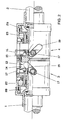
- the hydraulic drive unit shown in Figures 1 to 3 is part of a rotary drive, which serves to rotate the ends of two barber halves 1, 2.
- the stabilizer halves 1, 2 are part of a Kraft mecanical stabilisators not shown here.
- the other ends of the stabilizer halves 1 and 2, not shown, are fixed to the wheel suspension of a respective wheel of a motor vehicle axle and serve to reduce rolling movements of the body about the vehicle longitudinal axis occurring when cornering a motor vehicle due to the lateral acceleration.
- the hydraulic drive unit according to the invention is part of the rotary drive, which is essentially composed of two mutually rotatable housing halves 3 and 4, which are each connected via a arranged on each housing half 3, 4 flange 5, 6 rotatably connected to the stabilizer ends 1 and 2.
- an axial ball bearing 7 which allows the rotational movement of the housing halves 3 and 4 against each other.
- the housing halves 3 and 4 are braced against each other via a central threaded pin 8.
- a fixed partition 9 Centrally in the middle of the rotary drive formed by the two housing halves 3 and 4 is a fixed partition 9, which is arranged in the interior of an actuating piston 13 formed by two side walls and a cylindrical connecting web 12 is. Due to the design of the actuating piston 13 in conjunction with the partition wall 9, two piston chambers 14 and 15 are created, which can be acted upon by located in the side walls 10 and 11 ports 16 with oil pressure.
- the terminal 16 is shown for the piston chamber 15, a similar connection for the piston chamber 14 is not visible on the figures radially offset in the side wall 10 of the actuating piston 13.
- the side walls 10 and 11 are located next to the Disposed ports 16 for the oil supply over the circumference three projecting over the circumference of the side walls cam 17 which are arranged distributed over the circumference of the cylindrical side walls 10 and 11 by 120 °.
- the cams 17 are provided in their over the circumference of the side walls 10 protruding region, each with a needle bearing 18 which are recessed in slot-shaped openings 19 in the outer walls of the cylindrical housing halves 3 and 4.
- cam mechanism comprising a translational movement of the actuating piston 13 in the direction of the arrows P 1 and P 2 into a rotational movement according to the arrows Q 1 , Q 2 for the housing half 3 and S 1 and S 2 for the housing half 4 converts.
- the operating state is described with reference to FIG 2, in which the piston chamber 14 is acted upon via one of the terminals 16 by a hydraulic pump 21 with pressure oil.
- the piston chamber 14 increases and causes a translational displacement of the actuating piston 13 in the direction of the arrow P 1st
- the cams 17 arranged in the side walls 10 and 11 move simultaneously with the actuating piston 13.
- the movement of the actuating piston 13 is in the direction of the arrow P 1 simultaneously causes a rotation of the housing halves 3 in the direction of the arrow Q 1 , whereas the housing half 4 by the movement of the actuating piston 13 in the direction of the Arrow S 2 is rotated in opposite directions.
- the admission of the piston chamber 14 with a certain amount of pressure oil corresponds to a corresponding rotation of the ends of the stabilizer halves 1 and 2 against each other.
- Solution of the present invention is to develop the described rotary drive so that an uncontrolled translational movement of the actuating piston 13 is excluded in the event of failure of the hydraulic system or the electrical system of the motor vehicle.
- Figure 3 illustrates how the operating state shown in Figures 1 and 2 changes as soon as an error occurs within the hydraulic or electrical network of the motor vehicle. It can be seen from FIG. 3 that a lack of pressurized oil supply to the entire device arrangement on the one hand allows a displacement of the actuating piston 13 and at the same time a displacement of the release pistons 22 and 23 as a result of the relaxation due to the lack of pressurized oil supply to the piston chambers 24 and 25 the air within the compressed air cushion 28 and 29 is effected.
- the stored spring forces of the compressed air cushion push the release piston 22 and 23 in the direction of the actuating piston 13 until the end face of the release piston with the outer sides of the side walls 10 and 11 of the actuating piston 13 come into contact.
- the actuating piston 13 is pressed into the central position shown in FIG. 1, provided it has been displaced in the direction of the arrow P 1 , for example, according to FIG. The actuating piston 13 is then fixed in the central position, so that a neutral position of the entire axle stabilizer arrangement is ensured.
- the bias of the release pistons 22 and 23 in intaktem hydraulic and Elektrikboranzetz when commissioning the vehicle due to the pressure oil buildup of the hydraulic pump 21 in the piston chambers 24 and 25 is usually brought about in a time frame of less than 1 second.
- the poppet valve 30 fixes the biased state of the release pistons 22 and 23 so that the entire axle stabilizer system is operational.
- the operational readiness means that the release pistons are located in the outer position shown in Figures 1 and 2, so that the actuating piston 13 is displaceable in the direction of the arrows P 1 and P 2 .
- the spring bias is provided by a coil spring 31.
- the illustration of Figure 4 shows the normal operating state of the hydraulic drive unit, in which the release pistons 22 and 23 are in the spring preload position. In this position, there is the possibility of a displacement in the direction of the ends of the stabilizer halves 1 and 2 depending on the Druckölbeetzstoffung the piston chambers 14 and 15 for the actuating piston.
Landscapes
- Engineering & Computer Science (AREA)
- Mechanical Engineering (AREA)
- Vehicle Body Suspensions (AREA)
- Actuator (AREA)
- Fluid-Pressure Circuits (AREA)
- Transmission Devices (AREA)
Description
- Die Erfindung betrifft eine hydraulische Antriebseinheit für die koaxiale Verdrehbewegung zweier Stabilisatorhälften eines Kraftfahrzeugachsstabilisators mit einem aus zwei Gehäusehälften bestehenden, rohrförmigen Gehäuse, in dessen Innern ein hydraulisch bewegbarer Betätigungskolben verschieblich zur Gehäuselängsachse angeordnet ist, wobei die Längsverschiebung mittels eines zwischengeschalteten Kurvengetriebes in eine Drehbewegung der Gehäusehälften um ihre gemeinsame Längsachse umgeformt wird und wobei die Gehäusehälften mit ihrem jeweiligen freien, einander abgewandten Ende an jeweils einer Stabilisatorhälfte festgelegt sind.
- Achsstabilisatoren, für die die gattungsgemäße Antriebseinheit konzipiert ist, dienen allgemein dazu, bei Kurvenfahrten eines Kraftfahrzeuges auf Grund der Querbeschleunigung auftretende Wankbewegungen der Karosserie um die Fahrzeuglängsachse zu mindern oder ganz zu kompensieren. Die in der Regel zur selben Fahrzeugachse gehörenden Radträger sind dabei über einen geteilten Achsstabilisatorstab miteinander verbunden, wobei die Achsstabilisatorteile gleichzeitig drehbar am Fahrzeugaufbau über gesonderte Lagerelemente festgelegt sind. Die gegenüber liegenden nicht am Radträger festgelegten Enden der Stabilisatorhälften sind mittels eines zwischengeschalteten Drehantriebes gekoppelt. Die zwischen den beiden Stabilisatorhälften angeordnete Antriebseinheit als Bestandteil des Drehantriebes dient dabei zur Verdrehung der Achsstabilisatorenden gegeneinander, was gegebenenfalls die Wankstabilität des Fahrzeuges deutlich heraufsetzt.
- Bei Einsatz derartiger hydraulischer Antriebseinheiten ist aus Sicherheitsaspekten zu gewährleisten, dass bei Ausfall des zugehörigen Hydraulikkreises oder bei Fehlern im elektrischen Kraftfahrzeugbordnetz keine unkontrollierte Verstellung des Drehantriebes und somit eine ungewollte Veränderung der Achsstabilisatoreigenschaften herbeigeführt wird. Zu diesem Zweck sind die aus dem Stand der Technik bekannten hydraulischen Antriebseinheiten mit kosten- und platzaufwändigen Druckspeichern nebst dazugehörigen Ventilsystemen ausgestattet.
- Zum technischen Umfeld wird auf die DE-A-10 037 486 verwiesen
- Wünschenswert ist darüber hinaus bei oben geschilderten Ausfällen der Hydraulik oder Elektrik des Kraftfahrzeuges eine automatische Verstellung des Drehantriebes in eine vordefinierte Neutralposition, in der die Achsstabilisatorbaugruppe eine mittlere Drehsteifigkeit aufweist.
- Aufgabe der vorliegenden Erfindung ist es daher, eine Antriebseinheit der eingangs geschilderten gattungsgemäßen Art mit einer Sicherheitseinrichtung zu versehen, die im Falle eines Versagens des Systems auf einfache und kostengünstige Weise eine Festlegung der Stabilisatorverstellung in einer vordefinierten Neutrallage sicherstellt.
- Diese Aufgabe wird zusammen mit den gattungsbildenden Merkmalen durch die im kennzeichnenden Teil des Anspruches 1 offenbarte technische Lehre gelöst.
- Weitere Ausgestaltungen sind Gegenstand der sich anschließenden Unteransprüche.
- An den gegenüberliegenden Flachseiten des Betätigungskolbens können jeweils gegen ein Federelement vorspannbare hydraulisch betätigte Freigabekolben angeordnet sind, wobei die jeweiligen Freigabekolben in vorgespannter Position die Verschiebebewegung des Betätigungskolbens ermöglichen und in entspannter Position den Betätigungskolben in seiner Mittenposition festlegen.
- Die konstruktive Gestaltung ermöglicht eine Platz sparende Bauweise und dient dazu, die hydraulisch herbeigeführte Vorspannung des Freigabekolbens im Falle eines Ausfalls der Elektrik, Pneumatik oder des Hydrauliksystems für eine Längsverstellung des die Verdrehung der Stabilisatoranordnung bewirkenden Betätigungskolbens zu nutzen. Die Federkraft für die Verschiebung des Betätigungskolbens kann dabei vorteilhafterweise durch eine Luftfeder aufgebracht werden, darüber hinaus ist auch der Einsatz von Schraubenfedern auf Grund ihrer kompakten Abmessungen denkbar.
- Entsprechend einer vorteilhaften Weiterbildung des Gegenstandes der Erfindung kann die Antriebseinheit eine hydraulische Antriebseinheit sein und ist es insbesondere im Hinblick auf kompakte Baumaße der gesamten Stabilisatorverstelleinheit vorteilhaft, wenn die Freigabekolben und der Betätigungskolben konzentrisch zur Längsachse der hydraulischen Antriebseinheit angeordnet sind.
- Um unnötige Belastungen der für den Hydraulikkreislauf zuständigen Hydraulikpumpe zu vermeiden, kann es darüber hinaus zweckmäßig sein, die Steuerung der Freigabekolben und das Halten Letzterer in ihrer Vorspannposition durch ein elektrisch betätigtes Sitzventil zu realisieren. Wenn vorliegend von Hydraulik gesprochen wurde, so ist es selbstverständlich im Sinne der Erfindung auch möglich, andere Medien oder Energien (Pneumatik, Elektrik, etc.) zu nutzen, um das System oder Teile davon zu betreiben.
- Im Folgenden wird ein Ausführungsbeispiel des Gegenstandes der Erfindung anhand der beigefügten Zeichnen näher erläutert.
- Es zeigt:
- Figur 1
- eine Halbschnittdarstellung durch eine hydraulische Antriebseinheit zur Verdrehung de Enden zweier Stabilisatorhälften eines Kfz- Achsstabilisators gegeneinander,
- Figur 2
- eine Teilschnittdarstellung des Ausführungsbeispiels aus Figur 1 im Betriebszustand gegeneinander verdrehter Stabilisatorhälften,
- Figur 3
- eine Teilschnittdarstellung des Ausführungsbeispiels der Figuren 1 und 2 in der Betriebsposition bei Ausfall des angeschlossenen Hydrauliknetzes und
- Figur 4
- eine Teilschnittdarstellung durch eine weitere Ausführungsvariante ähnlich des Ausführungsbeispiels der Figuren 1 bis 3.
- Die in den Figuren 1 bis 3 dargestellte hydraulische Antriebseinheit ist Bestandteil eines Drehantriebes, der zur Verdrehung der Enden zweier Stabüisatorhälften 1, 2 dient. Die Stabilisatorhälften 1, 2 sind Bestandteil eines hier nicht näher dargestellten Kraftfahrzeugachsstabilisators. Die nicht dargestellten anderen Enden der Stabilisatorhälften 1 und 2 sind dabei an der Radaufhängung jeweils eines Rades einer Kraftfahrzeugachse festgelegt und dienen dazu, bei Kurvenfahrten eines Kraftfahrzeuges auf Grund der Querbeschleunigung auftretende Wankbewegungen der Karosserie um die Fahrzeuglängsachse zu vermindern.
- Die erfindungsgemäße hydraulische Antriebseinheit ist Bestandteil des Drehantriebes, welcher im Wesentlichen aus zwei gegeneinander verdrehbaren Gehäusehälften 3 und 4 aufgebaut ist, welche jeweils über einen an jeder Gehäusehälfte 3, 4 angeordneten Flansch 5, 6 drehfest mit den Stabilisatorenden 1 und 2 verbunden sind.
- In der Mitte zwischen den beiden Gehäusehälften befindet sich ein Axialkugellager 7, welches die Verdrehbewegung der Gehäusehälften 3 und 4 gegeneinander ermöglicht. Die Gehäusehälften 3 und 4 sind dabei über einen zentrischen Gewindezapfen 8 gegeneinander verspannt. Zentral in der Mitte des durch die beiden Gehäusehälften 3 und 4 gebildeten Drehantriebes befindet sich eine feste Trennwand 9, welche im Innern eines durch zwei Seitenwände und einen zylinderförmigen Verbindungssteg 12 gebildeten Betätigungskolben 13 angeordnet ist. Durch die Bauweise des Betätigungskolbens 13 in Verbindung mit der Trennwand 9 werden zwei Kolbenräume 14 und 15 geschaffen, welche durch in den Seitenwänden 10 und 11 befindliche Anschlüsse 16 mit Öldruck beaufschlagbar sind.
- In allen Figuren 1 bis 4 ist der Anschluss 16 für den Kolbenraum 15 dargestellt, ein gleichartiger Anschluss für den Kolbenraum 14 befindet sich auf den Figuren nicht sichtbar radial versetzt in der Seitenwand 10 des Betätigungskolbens 13. In den Seitenwänden 10 und 11 befinden sich neben den Anschlüssen 16 für die Ölversorgung über den Umfang verteilt drei über den Umfang der Seitenwände vorstehende Nocken 17, die über den Umfang der zylinderförmigen Seitenwandungen 10 und 11 um 120° verteilt angeordnet sind. Die Nocken 17 sind in ihrem über den Umfang der Seitenwände 10 vorstehenden Bereich mit jeweils einem Nadellager 18 versehen, welche in langlochförmige Durchbrüche 19 in den Außenwandungen der zylinderförmigen Gehäusehälften 3 und 4 ausgespart sind.
- Die in den Seitenwandungen 10 und 11 angeordneten Nocken bilden zusammen mit den über den Umfang der Gehäusewandungen 20 verteilten Durchbrüchen 19 ein Kurvengetriebe, welches eine translatorische Bewegung des Betätigungskolbens 13 in Richtung der Pfeile P1 bzw. P2 in eine Drehbewegung entsprechend der Pfeile Q1, Q2 für die Gehäusehälfte 3 und S1 bzw. S2 für die Gehäusehälfte 4 umsetzt.
- Zur Erläuterung der Wirkungsweise des Drehantriebes wird der Betriebszustand anhand der Figur 2 beschrieben, in dem der Kolbenraum 14 über einen der Anschlüsse 16 durch eine Hydraulikpumpe 21 mit Drucköl beaufschlagt wird. Durch diese Maßnahme vergrößert sich der Kolbenraum 14 und bewirkt eine translatorische Verschiebung des Betätigungskolbens 13 in Richtung des Pfeiles P1. Durch diese Verschiebung bewegen sich gleichzeitig mit dem Betätigungskolben 13 die in den Seitenwandungen 10 und 11 angeordneten Nocken 17. Da die Gehäusehälften 3 und 4 bzw. die Durchbrüche 19 durch die Nocken 17 zwangsgeführt sind, wird durch die Bewegung des Betätigungskolbens 13 in Richtung des Pfeiles P1 gleichzeitig eine Verdrehung der Gehäusehälften 3 in Richtung des Pfeiles Q1 bewirkt, wohingegen die Gehäusehälfte 4 durch die Bewegung des Betätigungskolbens 13 in Richtung des Pfeiles S2 entgegengesetzt verdreht wird. Somit entspricht die Beaufschlagung des Kolbenraumes 14 mit einer bestimmten Druckölmenge einer entsprechenden Verdrehung der Enden der Stabilisatorhälften 1 und 2 gegeneinander.
- Sollte im angeschlossenen Hydraulikkreislauf ein Leitungsbruch auftreten oder sollte die Hydraulikpumpe auf Grund eines Defektes im elektrischen Kraftfahrzeugbordnetz keine Leistung bereitstellen, so entfällt naturgemäß die Druckbeaufschlagung innerhalb des Kolbenraumes 14, so dass eine unkontrollierte Verschiebung des Betätigungskolbens 13 möglich wäre.
- Lösung der vorliegenden Erfindung ist es, den geschilderten Drehantrieb so weiter zu entwickeln, dass eine unkontrollierte translatorische Bewegung des Betätigungskolbens 13 im Falle eines Ausfalls der Hydraulik oder der Elektrik des Kraftfahrzeuges ausgeschlossen wird.
- Zu diesem Zweck befinden sich innerhalb der Gehäusehälften 3 und 4 jeweils an der den Kolbenräumen 14 und 15 abgewandten Außenseite des Betätigungskolbens je ein gegen eine Federkraft vorspannbarer hydraulisch betätigter Freigabekolben 22 bzw. 23. Die Druckölbeaufschlagung der genannten Freigabekolben 22 bzw. 23 erfolgt auf den zwischen Freigabekolben 22 bzw. 23 und Gehäusewandung definierte Kolbenräume 24 und 25, die über Anschlüsse 26 bzw. 27 von der Hydraulikpumpe 21 mit Drucköl beaufschlagt sind. An der den Kolbenräumen 24 und 25 abgewandten gegenüber liegenden Seite der Freigabekolben 22 und 23 befindet sich jeweils ein Druckluftpolster 28 bzw. 29, welche in der Darstellung der Figuren 1 und 2 auf Grund der durch die Druckölbeaufschlagung der Kolbenräume 24 und 25 erfolgten Verschiebung der Freigabekolben 22 und 23 in Richtung der Pfeile T1 und T2 komprimiert sind. Die Komprimierung des in den Druckluftpolsterräumen 28 und 29 enthaltenen Druckmediums ruft eine Federkraft hervor, welche während des normalen Betriebszustandes der hydraulischen Antriebseinheit mit dem innerhalb der Kolbenräume 24 und 25 befindlichen Drucköl im Gleichgewicht steht. Dieser Zustand wird mittels des elektrisch betätigten Sitzventiles 30 aufrechterhalten.
- In der Darstellung der Figur 3 ist verdeutlicht, wie sich der in den Figuren 1 und 2 dargestellte Betriebszustand verändert, sobald innerhalb des Hydraulik- oder Elektriknetzes des Kraftfahrzeuges ein Fehler auftritt. Erkennbar ist aus der Figur 3, dass eine fehlende Druckölbeaufschlagung der gesamten Geräteanordnung zum einen - wie bereits eingangs geschildert - eine Verschiebung des Betätigungskolbens 13 ermöglicht und gleichzeitig durch die fehlende Druckölbeaufschlagung der Kolbenräume 24 und 25 eine Verschiebung der Freigabekolben 22 und 23 in Folge der Entspannung der Luft innerhalb der Druckluftpolster 28 und 29 bewirkt wird. Die gespeicherten Federkräfte der Druckluftpolster drücken die Freigabekolben 22 und 23 in Richtung des Betätigungskolbens 13, bis die Stirnfläche der Freigabekolben mit den Außenseiten der Seitenwandungen 10 und 11 des Betätigungskolbens 13 in Berührung kommen. Durch die symmetrische Ausführung der Freigabekolben 22 und 23 wird der Betätigungskolben 13 in die in der Figur 1 dargestellte Mittellage gedrückt, sofern er beispielsweise entsprechend der Figur 2 in Richtung des Pfeiles P1 verschoben war. Der Betätigungskolben 13 wird sodann in der Mittellage fixiert, so dass eine Neutralstellung der gesamten Achsstabilisatoranordnung gewährleistet ist.
- Anzumerken ist in diesem Zusammenhang, dass die Vorspannung der Freigabekolben 22 und 23 bei intaktem Hydraulik- und Elektrikboränetz bei Inbetriebnahme des Fahrzeuges in Folge des Druckölaufbaus der Hydraulikpumpe 21 in den Kolbenräumen 24 und 25 üblicherweise in einem Zeitrahmen von weniger als 1 Sekunde herbeigeführt wird. Danach fixiert das Sitzventil 30 den vorgespannten Zustand der Freigabekolben 22 und 23, so dass das gesamte Achsstabilisatorsystem betriebsbereit ist. Die Betriebsbereitschaft bedeutet, dass die Freigabekolben in der in den Figuren 1 und 2 dargestellten äußeren Position befindlich sind, so dass der Betätigungskolben 13 in Richtung der Pfeile P1 bzw. P2 verschieblich ist.
- In der Darstellung der Figur 4 ist ergänzend eine weitere Ausführungsvariante des Erfindungsgegenstandes dargestellt, welche sich im Wesentlichen durch die Art der Bereitstellung der Federvorspannung von dem in den Figuren 1 bis 3 beschriebenen Ausführungsbeispiel unterscheidet.
- Es wird deshalb auf eine nochmalige Beschreibung der Einzelteile des erfindungsgemäßen Ausführungsbeispieles verzichtet. Wesentlich ist, dass in dem in Figur 4 dargestellten Ausführungsbeispiel die Federvorspannung durch eine Schraubenfeder 31 bereitgestellt ist. Die Darstellung der Figur 4 zeigt den normalen Betriebszustand der hydraulischen Antriebseinheit, bei der sich die Freigabekolben 22 bzw. 23 in der Federvorspannungsposition befinden. In dieser Position besteht für den Betätigungskolben 13 die Möglichkeit einer Verschiebung in Richtung der Enden der Stabilisatorhälften 1 bzw. 2 je nach Druckölbeaufschlagung der Kolbenräume 14 und 15.
- Natürlich sind für die Bereitstellung der Federvorspannkräfte auch noch andere Federvarianten, wie beispielsweise Tellerfedern, denkbar. Erfindungswesentlich ist, dass bei einem Ausfall der Hydraulik oder der Elektrik des betreffenden Kraftfahrzeuges durch die Freisetzung der Federvorspannkräfte in Folge der Rückbewegung der Freigabekolben 22 und 23 eine Verschiebung des Betätigungskolbens 13 in seine mittige Neutralposition herbeigeführt wird, wobei gleichzeitig die an den Betätigungskolben 13 mittels der Nocken 19 gekoppelten Gehäusehälften 3 und 4 aus ihrer verdrehten Position in die Neutralposition zurückbewegt werden.
-
- 1.
- Stabilisatorhälfte
- 2.
- Stabilisatorhälfte
- 3.
- Gehäusehälfte
- 4.
- Gehäusehälfte
- 5.
- Flansch
- 6.
- Flansch
- 7.
- Axialkugellager
- 8.
- Gewindezapfen
- 9.
- Trennwand
- 10.
- Seitenwand
- 11.
- Seitenwand
- 12.
- Verbindungssteg
- 13.
- Betätigungskolben
- 14.
- Kolbenraum
- 15.
- Kolbenraum
- 16.
- Anschluss
- 17.
- Nocke
- 18.
- Nadellager
- 19.
- Durchbruch
- 20.
- Gehäusewandung
- 21.
- Hydraulikpumpe
- 22.
- Freigabekolben
- 23.
- Freigabekolben
- 24.
- Kolbenraum
- 25.
- Kolbenraum
- 26.
- Anschluss
- 27.
- Anschluss
- 28.
- Druckluftpolster
- 29.
- Druckluftpolster
- 30.
- Sitzventil
- 31.
- Schraubenfeder
Claims (6)
- Antriebseinheit für die koaxiale Verdrehbewegung zweier Stabilisatorhälften (1,2) eines Kraftfahrzeugachsstabilisators mit einem aus zwei Gehäusehälften (3, 4) bestehenden, rohrförmigen Gehäuse, in dessen Innern ein hydraulisch bewegbarer Betätigungskolben (13) verschieblich zur Gehäuselängsachse angeordnet ist, wobei die Längsverschiebung mittels eines zwischengeschalteten Kurvengetriebes (19, 17) in eine Drehbewegung der Gehäusehälften (3, 4) um ihre gemeinsame Längsachse umgeformt wird und wobei die Gehäusehälften (3, 4) mit ihrem jeweiligen freien, einander abgewandten Ende an jeweils einer Stabilisatorhälfte (1, 2) festgelegt sind,
dadurch gekennzeichnet, dass
an den gegenüberliegenden Flachseiten des Betätigungskolbens (13) jeweils gegen ein Federelement (28, 29, 31) in vorgespannter Position die Verschiebebewegung des zentralen Betätigungskolbens (13) ermöglichende und in entspannter Position den Betätigungskolben (13) in seiner Mittenposition festlegende vorspannbare hydraulisch betätigte Freigabekolben (22, 23) angeordnet sind. - Antriebseinheit nach Anspruch 1,
dadurch gekennzeichnet, dass
die Antriebseinheit eine hydraulische Antriebseinheit ist. - Antriebseinheit nach Anspruch 1 oder 2,
dadurch gekennzeichnet, dass
die Federkraft zur Vorspannung des Freigabekolbens (22, 23) durch ein als Druckluftpolster (28, 29)ausgebildetes Federelement bereitgestellt ist. - Antriebseinheit nach Anspruch 1 oder 2,
dadurch gekennzeichnet, dass
die Federkraft zur Vorspannung des Freigabekolbens (22, 23) durch ein als Schraubenfeder (31) ausgebildetes Federelement bereitgestellt ist. - Antriebseinheit nach einem der vorstehend genannten Ansprüche,
dadurch gekennzeichnet, dass
der Freigabekolben in seiner Vorspannposition durch ein elektrisch betätigtes Sitzventil (20) gehalten ist.. - Antriebseinheit nach einem der vorstehend genannten Ansprüche,
dadurch gekennzeichnet, dass
Freigabekolben (22, 23) und Betätigungskolben (13) konzentrisch zur Längsachse der hydraulischen Antriebseinheit angeordnet sind.
Applications Claiming Priority (3)
| Application Number | Priority Date | Filing Date | Title |
|---|---|---|---|
| DE10242724 | 2002-09-13 | ||
| DE10242724A DE10242724B4 (de) | 2002-09-13 | 2002-09-13 | Antriebseinheit für einen Kraftfahrzeugachsstabilisator |
| PCT/DE2003/003047 WO2004026601A1 (de) | 2002-09-13 | 2003-09-12 | Antriebseinheit für einen kraftfahrzeugachsstabilisator |
Publications (2)
| Publication Number | Publication Date |
|---|---|
| EP1536960A1 EP1536960A1 (de) | 2005-06-08 |
| EP1536960B1 true EP1536960B1 (de) | 2006-04-12 |
Family
ID=31969130
Family Applications (1)
| Application Number | Title | Priority Date | Filing Date |
|---|---|---|---|
| EP03756437A Expired - Lifetime EP1536960B1 (de) | 2002-09-13 | 2003-09-12 | Antriebseinheit für einen kraftfahrzeugachsstabilisator |
Country Status (8)
| Country | Link |
|---|---|
| US (1) | US7044048B2 (de) |
| EP (1) | EP1536960B1 (de) |
| JP (1) | JP2005538329A (de) |
| CN (1) | CN1642763A (de) |
| AT (1) | ATE322999T1 (de) |
| DE (2) | DE10242724B4 (de) |
| ES (1) | ES2260648T3 (de) |
| WO (1) | WO2004026601A1 (de) |
Families Citing this family (12)
| Publication number | Priority date | Publication date | Assignee | Title |
|---|---|---|---|---|
| US7156406B2 (en) * | 2002-10-25 | 2007-01-02 | Ina- Schaeffler Kg | Anti-roll bar for the chassis of a motor vehicle |
| US7287759B2 (en) * | 2003-09-30 | 2007-10-30 | Kabushiki Kaisha Hitachi Seisakusho | Stabilizer device |
| US7494132B2 (en) * | 2005-06-28 | 2009-02-24 | Arvinmeritor Technology, Llc | Roll control actuator with piston assembly |
| FR2889866B1 (fr) | 2005-07-29 | 2007-10-19 | France Reducteurs Soc Par Acti | Variateur de vitesse a courroie et engin automoteur a vitesse d'avancement variable equipe d'un tel variateur |
| DE102006028878A1 (de) * | 2006-06-21 | 2007-12-27 | Zf Friedrichshafen Ag | Hydraulische Stelleinheit für ein Kraftfahrzeug |
| DE202006016354U1 (de) * | 2006-10-23 | 2008-02-28 | Asturia Automotive Systems Ag | Einrichtung zum Ausgleich und/oder zur Übertragung von Kräften/Momenten und Drehbewegungen zwischen zwei Bauteilen |
| DE202007013613U1 (de) * | 2007-09-27 | 2009-02-12 | Asturia Automotive Systems Ag | Druckmittelbetätigbarer Schwenkmotor |
| JP5108684B2 (ja) * | 2008-08-28 | 2012-12-26 | 日産自動車株式会社 | 回転駆動装置、および多関節アーム装置 |
| CN101980878B (zh) * | 2009-04-06 | 2012-12-12 | 丰田自动车株式会社 | 车辆用稳定器装置 |
| DE102011106246A1 (de) * | 2011-07-01 | 2013-01-03 | Audi Ag | Stellvorrichtung für eine Kraftfahrzeug-Radaufhänung |
| DE102011090089A1 (de) * | 2011-12-29 | 2013-07-04 | Robert Bosch Gmbh | Federbein eines Kraftfahrzeugs |
| CN117231591B (zh) * | 2023-10-30 | 2024-12-20 | 国家智能制造装备产品质量监督检验中心(浙江) | 一种液压马达扭矩测试系统及试验方法 |
Family Cites Families (7)
| Publication number | Priority date | Publication date | Assignee | Title |
|---|---|---|---|---|
| GB518238A (en) * | 1938-08-19 | 1940-02-21 | Albert Frank Collins | Improvements in or relating to reciprocating engines |
| US2757938A (en) * | 1954-04-09 | 1956-08-07 | Charles W Crowder | Hydraulic motor vehicle stabilizer |
| US2808033A (en) * | 1955-07-27 | 1957-10-01 | Hydro Torque Inc | Torque unit |
| US3198539A (en) * | 1962-07-17 | 1965-08-03 | Wayne W Mcmullen | Hydraulic torque cylinder |
| DE4135928A1 (de) * | 1991-10-31 | 1993-05-06 | Mercedes-Benz Aktiengesellschaft, 7000 Stuttgart, De | Stabilisierungsanordnung fuer kraftfahrzeuge |
| GB2350592B (en) * | 1999-06-04 | 2002-09-25 | Delphi Tech Inc | Roll control actuator |
| DE10037486A1 (de) * | 2000-08-01 | 2002-02-14 | Zf Lenksysteme Gmbh | Aktuator |
-
2002
- 2002-09-13 DE DE10242724A patent/DE10242724B4/de not_active Expired - Fee Related
-
2003
- 2003-09-12 WO PCT/DE2003/003047 patent/WO2004026601A1/de not_active Ceased
- 2003-09-12 ES ES03756437T patent/ES2260648T3/es not_active Expired - Lifetime
- 2003-09-12 EP EP03756437A patent/EP1536960B1/de not_active Expired - Lifetime
- 2003-09-12 JP JP2004536869A patent/JP2005538329A/ja active Pending
- 2003-09-12 CN CN03805919.3A patent/CN1642763A/zh active Pending
- 2003-09-12 AT AT03756437T patent/ATE322999T1/de not_active IP Right Cessation
- 2003-09-12 DE DE50302968T patent/DE50302968D1/de not_active Expired - Fee Related
-
2004
- 2004-07-20 US US10/895,148 patent/US7044048B2/en not_active Expired - Fee Related
Also Published As
| Publication number | Publication date |
|---|---|
| CN1642763A (zh) | 2005-07-20 |
| US7044048B2 (en) | 2006-05-16 |
| DE50302968D1 (de) | 2006-05-24 |
| EP1536960A1 (de) | 2005-06-08 |
| WO2004026601A1 (de) | 2004-04-01 |
| ES2260648T3 (es) | 2006-11-01 |
| DE10242724A1 (de) | 2004-04-01 |
| JP2005538329A (ja) | 2005-12-15 |
| US20040262858A1 (en) | 2004-12-30 |
| ATE322999T1 (de) | 2006-04-15 |
| DE10242724B4 (de) | 2004-10-14 |
Similar Documents
| Publication | Publication Date | Title |
|---|---|---|
| EP0850151B1 (de) | Einrichtung zur rollstabilisierung eines fahrzeugs | |
| EP1536960B1 (de) | Antriebseinheit für einen kraftfahrzeugachsstabilisator | |
| DE19902556B4 (de) | Lenkgetrieb mit redundantem Antrieb | |
| EP2430275B1 (de) | Klappenantriebssystem | |
| DE102017123266A1 (de) | Mechanische Bremsvorrichtung | |
| EP1554138B1 (de) | Wankstabilisator für das fahrwerk eines kraftfahrzeugs | |
| EP1984656B1 (de) | Schaltvorrichtung für kraftfahrzeug-wechselgetriebe | |
| DE102013002714A1 (de) | Drehfedersystem für eine Radaufhängung eines Kraftfahrzeugs | |
| DE102014226120A1 (de) | Kennungswandler mit Kurvenscheibe und Lagerpendel zur Betätigung einer Kupplung | |
| EP1785294B1 (de) | Verstellbare Stabilisatoranordnung | |
| EP1831039A2 (de) | Aktives fahrwerkstabilisierungssystem | |
| EP1554139A1 (de) | Wankstabilisator für das fahrwerk eines kraftfahrzeugs | |
| DE3411054A1 (de) | Mechanische loeseeinrichtung fuer einen federspeicherbremszylinder | |
| DE2234410C3 (de) | Querkupplungssystem für Schienenfahrzeuge mit mehrachsigen Drehgestellen | |
| EP1529715A2 (de) | Nutzfahrzeuglenkung | |
| EP0003026B1 (de) | Schnellösevorrichtung für Federspeicherbremszylinder mit Dämpfungseinrichtung | |
| DE3410033A1 (de) | Vorrichtung zur hydraulischen unterstuetzung der lenkkraft | |
| EP1879758B1 (de) | Geteilter elektromechanischer kraftfahrzeugstabilisator mit blockiereinrichtung und verfahren zur wankstabilisierung bei ausfall oder abschaltung des aktiven kraftfahrzeugstabilisators | |
| WO2008116630A2 (de) | Kompakt-kombizylinder für fahrzeugbremsen mit steuerungsvorrichtung und verfahren zur ansteuerung des bremszylinders | |
| DE102015209611A1 (de) | Kennungswandler mit Kurvenscheibe und Querkraft- minimiert positioniertem Stößel zur Betätigung einer Kupplung | |
| WO2013068110A1 (de) | Mechanischer lösemechanismus | |
| DE102007001544A1 (de) | Federungssystem für eine Fahrzeug-Radaufhängung mit zumindest einem zuschaltbaren Verdreh-Federelement | |
| DE102004040940A1 (de) | Baugruppe für ein Fahrwerkstabilisierungssystem | |
| DE10046524B4 (de) | Fremdkraftlenkanlage | |
| DE3909210A1 (de) | Elektrohydraulische lenkhilfe fuer kraftfahrzeuge |
Legal Events
| Date | Code | Title | Description |
|---|---|---|---|
| PUAI | Public reference made under article 153(3) epc to a published international application that has entered the european phase |
Free format text: ORIGINAL CODE: 0009012 |
|
| 17P | Request for examination filed |
Effective date: 20040518 |
|
| AK | Designated contracting states |
Kind code of ref document: A1 Designated state(s): AT BE BG CH CY CZ DE DK EE ES FI FR GB GR HU IE IT LI LU MC NL PT RO SE SI SK TR |
|
| GRAP | Despatch of communication of intention to grant a patent |
Free format text: ORIGINAL CODE: EPIDOSNIGR1 |
|
| GRAS | Grant fee paid |
Free format text: ORIGINAL CODE: EPIDOSNIGR3 |
|
| GRAA | (expected) grant |
Free format text: ORIGINAL CODE: 0009210 |
|
| AK | Designated contracting states |
Kind code of ref document: B1 Designated state(s): AT BE BG CH CY CZ DE DK EE ES FI FR GB GR HU IE IT LI LU MC NL PT RO SE SI SK TR |
|
| PG25 | Lapsed in a contracting state [announced via postgrant information from national office to epo] |
Ref country code: IE Free format text: LAPSE BECAUSE OF FAILURE TO SUBMIT A TRANSLATION OF THE DESCRIPTION OR TO PAY THE FEE WITHIN THE PRESCRIBED TIME-LIMIT Effective date: 20060412 Ref country code: RO Free format text: LAPSE BECAUSE OF FAILURE TO SUBMIT A TRANSLATION OF THE DESCRIPTION OR TO PAY THE FEE WITHIN THE PRESCRIBED TIME-LIMIT Effective date: 20060412 Ref country code: SI Free format text: LAPSE BECAUSE OF FAILURE TO SUBMIT A TRANSLATION OF THE DESCRIPTION OR TO PAY THE FEE WITHIN THE PRESCRIBED TIME-LIMIT Effective date: 20060412 Ref country code: CZ Free format text: LAPSE BECAUSE OF FAILURE TO SUBMIT A TRANSLATION OF THE DESCRIPTION OR TO PAY THE FEE WITHIN THE PRESCRIBED TIME-LIMIT Effective date: 20060412 Ref country code: SK Free format text: LAPSE BECAUSE OF FAILURE TO SUBMIT A TRANSLATION OF THE DESCRIPTION OR TO PAY THE FEE WITHIN THE PRESCRIBED TIME-LIMIT Effective date: 20060412 Ref country code: FI Free format text: LAPSE BECAUSE OF FAILURE TO SUBMIT A TRANSLATION OF THE DESCRIPTION OR TO PAY THE FEE WITHIN THE PRESCRIBED TIME-LIMIT Effective date: 20060412 |
|
| REG | Reference to a national code |
Ref country code: GB Ref legal event code: FG4D Free format text: NOT ENGLISH |
|
| REG | Reference to a national code |
Ref country code: CH Ref legal event code: EP |
|
| REF | Corresponds to: |
Ref document number: 50302968 Country of ref document: DE Date of ref document: 20060524 Kind code of ref document: P |
|
| REG | Reference to a national code |
Ref country code: IE Ref legal event code: FG4D Free format text: LANGUAGE OF EP DOCUMENT: GERMAN |
|
| GBT | Gb: translation of ep patent filed (gb section 77(6)(a)/1977) |
Effective date: 20060517 |
|
| PG25 | Lapsed in a contracting state [announced via postgrant information from national office to epo] |
Ref country code: DK Free format text: LAPSE BECAUSE OF FAILURE TO SUBMIT A TRANSLATION OF THE DESCRIPTION OR TO PAY THE FEE WITHIN THE PRESCRIBED TIME-LIMIT Effective date: 20060712 |
|
| REG | Reference to a national code |
Ref country code: SE Ref legal event code: TRGR |
|
| PG25 | Lapsed in a contracting state [announced via postgrant information from national office to epo] |
Ref country code: PT Free format text: LAPSE BECAUSE OF FAILURE TO SUBMIT A TRANSLATION OF THE DESCRIPTION OR TO PAY THE FEE WITHIN THE PRESCRIBED TIME-LIMIT Effective date: 20060912 |
|
| PG25 | Lapsed in a contracting state [announced via postgrant information from national office to epo] |
Ref country code: MC Free format text: LAPSE BECAUSE OF NON-PAYMENT OF DUE FEES Effective date: 20060930 Ref country code: BE Free format text: LAPSE BECAUSE OF NON-PAYMENT OF DUE FEES Effective date: 20060930 |
|
| ET | Fr: translation filed | ||
| REG | Reference to a national code |
Ref country code: ES Ref legal event code: FG2A Ref document number: 2260648 Country of ref document: ES Kind code of ref document: T3 |
|
| REG | Reference to a national code |
Ref country code: IE Ref legal event code: FD4D |
|
| PLBE | No opposition filed within time limit |
Free format text: ORIGINAL CODE: 0009261 |
|
| STAA | Information on the status of an ep patent application or granted ep patent |
Free format text: STATUS: NO OPPOSITION FILED WITHIN TIME LIMIT |
|
| PG25 | Lapsed in a contracting state [announced via postgrant information from national office to epo] |
Ref country code: DE Free format text: LAPSE BECAUSE OF NON-PAYMENT OF DUE FEES Effective date: 20070403 |
|
| 26N | No opposition filed |
Effective date: 20070115 |
|
| PGFP | Annual fee paid to national office [announced via postgrant information from national office to epo] |
Ref country code: AT Payment date: 20070912 Year of fee payment: 5 |
|
| BERE | Be: lapsed |
Owner name: ZF LEMFORDER METALLWAREN A.G. Effective date: 20060930 |
|
| PGFP | Annual fee paid to national office [announced via postgrant information from national office to epo] |
Ref country code: GB Payment date: 20070912 Year of fee payment: 5 |
|
| PGFP | Annual fee paid to national office [announced via postgrant information from national office to epo] |
Ref country code: ES Payment date: 20071024 Year of fee payment: 5 Ref country code: IT Payment date: 20070927 Year of fee payment: 5 Ref country code: NL Payment date: 20070903 Year of fee payment: 5 Ref country code: SE Payment date: 20070905 Year of fee payment: 5 |
|
| PG25 | Lapsed in a contracting state [announced via postgrant information from national office to epo] |
Ref country code: GR Free format text: LAPSE BECAUSE OF FAILURE TO SUBMIT A TRANSLATION OF THE DESCRIPTION OR TO PAY THE FEE WITHIN THE PRESCRIBED TIME-LIMIT Effective date: 20060713 |
|
| PGFP | Annual fee paid to national office [announced via postgrant information from national office to epo] |
Ref country code: FR Payment date: 20070914 Year of fee payment: 5 |
|
| REG | Reference to a national code |
Ref country code: CH Ref legal event code: PL |
|
| PG25 | Lapsed in a contracting state [announced via postgrant information from national office to epo] |
Ref country code: EE Free format text: LAPSE BECAUSE OF FAILURE TO SUBMIT A TRANSLATION OF THE DESCRIPTION OR TO PAY THE FEE WITHIN THE PRESCRIBED TIME-LIMIT Effective date: 20060412 Ref country code: BG Free format text: LAPSE BECAUSE OF FAILURE TO SUBMIT A TRANSLATION OF THE DESCRIPTION OR TO PAY THE FEE WITHIN THE PRESCRIBED TIME-LIMIT Effective date: 20060712 |
|
| PG25 | Lapsed in a contracting state [announced via postgrant information from national office to epo] |
Ref country code: LU Free format text: LAPSE BECAUSE OF NON-PAYMENT OF DUE FEES Effective date: 20060912 Ref country code: HU Free format text: LAPSE BECAUSE OF FAILURE TO SUBMIT A TRANSLATION OF THE DESCRIPTION OR TO PAY THE FEE WITHIN THE PRESCRIBED TIME-LIMIT Effective date: 20061013 Ref country code: LI Free format text: LAPSE BECAUSE OF NON-PAYMENT OF DUE FEES Effective date: 20070930 Ref country code: TR Free format text: LAPSE BECAUSE OF FAILURE TO SUBMIT A TRANSLATION OF THE DESCRIPTION OR TO PAY THE FEE WITHIN THE PRESCRIBED TIME-LIMIT Effective date: 20060412 Ref country code: CH Free format text: LAPSE BECAUSE OF NON-PAYMENT OF DUE FEES Effective date: 20070930 |
|
| PG25 | Lapsed in a contracting state [announced via postgrant information from national office to epo] |
Ref country code: CY Free format text: LAPSE BECAUSE OF FAILURE TO SUBMIT A TRANSLATION OF THE DESCRIPTION OR TO PAY THE FEE WITHIN THE PRESCRIBED TIME-LIMIT Effective date: 20060412 |
|
| GBPC | Gb: european patent ceased through non-payment of renewal fee |
Effective date: 20080912 |
|
| PG25 | Lapsed in a contracting state [announced via postgrant information from national office to epo] |
Ref country code: NL Free format text: LAPSE BECAUSE OF NON-PAYMENT OF DUE FEES Effective date: 20090401 |
|
| NLV4 | Nl: lapsed or anulled due to non-payment of the annual fee |
Effective date: 20090401 |
|
| REG | Reference to a national code |
Ref country code: FR Ref legal event code: ST Effective date: 20090529 |
|
| PG25 | Lapsed in a contracting state [announced via postgrant information from national office to epo] |
Ref country code: IT Free format text: LAPSE BECAUSE OF NON-PAYMENT OF DUE FEES Effective date: 20080912 Ref country code: AT Free format text: LAPSE BECAUSE OF NON-PAYMENT OF DUE FEES Effective date: 20080912 |
|
| PG25 | Lapsed in a contracting state [announced via postgrant information from national office to epo] |
Ref country code: FR Free format text: LAPSE BECAUSE OF NON-PAYMENT OF DUE FEES Effective date: 20080930 |
|
| REG | Reference to a national code |
Ref country code: ES Ref legal event code: FD2A Effective date: 20080913 |
|
| PG25 | Lapsed in a contracting state [announced via postgrant information from national office to epo] |
Ref country code: GB Free format text: LAPSE BECAUSE OF NON-PAYMENT OF DUE FEES Effective date: 20080912 |
|
| PG25 | Lapsed in a contracting state [announced via postgrant information from national office to epo] |
Ref country code: ES Free format text: LAPSE BECAUSE OF NON-PAYMENT OF DUE FEES Effective date: 20080913 |
|
| PG25 | Lapsed in a contracting state [announced via postgrant information from national office to epo] |
Ref country code: SE Free format text: LAPSE BECAUSE OF NON-PAYMENT OF DUE FEES Effective date: 20080913 |