EP1536610A2 - Procédé pour la transmission de données dans un système de communication - Google Patents
Procédé pour la transmission de données dans un système de communication Download PDFInfo
- Publication number
- EP1536610A2 EP1536610A2 EP04104643A EP04104643A EP1536610A2 EP 1536610 A2 EP1536610 A2 EP 1536610A2 EP 04104643 A EP04104643 A EP 04104643A EP 04104643 A EP04104643 A EP 04104643A EP 1536610 A2 EP1536610 A2 EP 1536610A2
- Authority
- EP
- European Patent Office
- Prior art keywords
- connection
- communication
- node
- unit
- oriented
- Prior art date
- Legal status (The legal status is an assumption and is not a legal conclusion. Google has not performed a legal analysis and makes no representation as to the accuracy of the status listed.)
- Granted
Links
- 238000004891 communication Methods 0.000 title claims abstract description 365
- 238000000034 method Methods 0.000 title claims abstract description 43
- 230000005540 biological transmission Effects 0.000 title claims abstract description 36
- 241000030781 Ippa Species 0.000 claims description 35
- YAONEUNUMVOKNQ-UHFFFAOYSA-N 15-(4-iodophenyl)pentadecanoic acid Chemical compound OC(=O)CCCCCCCCCCCCCCC1=CC=C(I)C=C1 YAONEUNUMVOKNQ-UHFFFAOYSA-N 0.000 claims description 34
- OUBMGJOQLXMSNT-UHFFFAOYSA-N N-isopropyl-N'-phenyl-p-phenylenediamine Chemical compound C1=CC(NC(C)C)=CC=C1NC1=CC=CC=C1 OUBMGJOQLXMSNT-UHFFFAOYSA-N 0.000 claims description 30
- 238000010276 construction Methods 0.000 claims description 14
- 230000011664 signaling Effects 0.000 claims description 10
- 101000610107 Homo sapiens Pre-B-cell leukemia transcription factor 1 Proteins 0.000 description 27
- 102100040171 Pre-B-cell leukemia transcription factor 1 Human genes 0.000 description 27
- 101000610110 Homo sapiens Pre-B-cell leukemia transcription factor 2 Proteins 0.000 description 26
- 102100040168 Pre-B-cell leukemia transcription factor 2 Human genes 0.000 description 26
- 102100040169 Pre-B-cell leukemia transcription factor 3 Human genes 0.000 description 23
- 108010051009 proto-oncogene protein Pbx3 Proteins 0.000 description 23
- 238000006243 chemical reaction Methods 0.000 description 22
- 101150073304 IPP1 gene Proteins 0.000 description 12
- 101150035463 PPP1R1A gene Proteins 0.000 description 12
- 102100024606 Protein phosphatase 1 regulatory subunit 1A Human genes 0.000 description 12
- 238000010586 diagram Methods 0.000 description 12
- 229930000044 secondary metabolite Natural products 0.000 description 10
- 101100048435 Caenorhabditis elegans unc-18 gene Proteins 0.000 description 9
- 101100072748 Arabidopsis thaliana IP5P12 gene Proteins 0.000 description 8
- 238000013461 design Methods 0.000 description 8
- 239000011159 matrix material Substances 0.000 description 8
- 101001050607 Homo sapiens KH domain-containing, RNA-binding, signal transduction-associated protein 3 Proteins 0.000 description 7
- 102100023428 KH domain-containing, RNA-binding, signal transduction-associated protein 3 Human genes 0.000 description 7
- 230000008878 coupling Effects 0.000 description 7
- 238000010168 coupling process Methods 0.000 description 7
- 238000005859 coupling reaction Methods 0.000 description 7
- 101100072743 Arabidopsis thaliana IP5P7 gene Proteins 0.000 description 6
- 101100402572 Arabidopsis thaliana MS5 gene Proteins 0.000 description 6
- 101000949825 Homo sapiens Meiotic recombination protein DMC1/LIM15 homolog Proteins 0.000 description 6
- 101001046894 Homo sapiens Protein HID1 Proteins 0.000 description 6
- 102100022877 Protein HID1 Human genes 0.000 description 6
- 238000012790 confirmation Methods 0.000 description 6
- 101100508878 Escherichia coli (strain K12) rsfS gene Proteins 0.000 description 5
- 101100292616 Saccharomyces cerevisiae (strain ATCC 204508 / S288c) SLM3 gene Proteins 0.000 description 5
- 150000001875 compounds Chemical class 0.000 description 5
- 230000008901 benefit Effects 0.000 description 4
- 230000015572 biosynthetic process Effects 0.000 description 4
- 230000000712 assembly Effects 0.000 description 3
- 238000000429 assembly Methods 0.000 description 3
- 238000005516 engineering process Methods 0.000 description 3
- VXPLXMJHHKHSOA-UHFFFAOYSA-N propham Chemical group CC(C)OC(=O)NC1=CC=CC=C1 VXPLXMJHHKHSOA-UHFFFAOYSA-N 0.000 description 3
- 238000012549 training Methods 0.000 description 3
- 238000012546 transfer Methods 0.000 description 3
- 101000599464 Homo sapiens Protein phosphatase inhibitor 2 Proteins 0.000 description 2
- 102100037976 Protein phosphatase inhibitor 2 Human genes 0.000 description 2
- 230000002457 bidirectional effect Effects 0.000 description 2
- 230000001419 dependent effect Effects 0.000 description 2
- 230000006872 improvement Effects 0.000 description 2
- 238000012986 modification Methods 0.000 description 2
- 230000004048 modification Effects 0.000 description 2
- 230000011218 segmentation Effects 0.000 description 2
- YLYPIBBGWLKELC-RMKNXTFCSA-N 2-[2-[(e)-2-[4-(dimethylamino)phenyl]ethenyl]-6-methylpyran-4-ylidene]propanedinitrile Chemical compound C1=CC(N(C)C)=CC=C1\C=C\C1=CC(=C(C#N)C#N)C=C(C)O1 YLYPIBBGWLKELC-RMKNXTFCSA-N 0.000 description 1
- ZNJRONVKWRHYBF-VOTSOKGWSA-N 4-(dicyanomethylene)-2-methyl-6-julolidyl-9-enyl-4h-pyran Chemical compound O1C(C)=CC(=C(C#N)C#N)C=C1\C=C\C1=CC(CCCN2CCC3)=C2C3=C1 ZNJRONVKWRHYBF-VOTSOKGWSA-N 0.000 description 1
- 101800001288 Atrial natriuretic factor Proteins 0.000 description 1
- 101800001890 Atrial natriuretic peptide Proteins 0.000 description 1
- -1 IPPB Chemical compound 0.000 description 1
- 238000011161 development Methods 0.000 description 1
- 230000018109 developmental process Effects 0.000 description 1
- 230000006870 function Effects 0.000 description 1
- 230000000977 initiatory effect Effects 0.000 description 1
- 230000003993 interaction Effects 0.000 description 1
- 238000012545 processing Methods 0.000 description 1
- 239000007858 starting material Substances 0.000 description 1
- 230000002123 temporal effect Effects 0.000 description 1
Images


Classifications
-
- H—ELECTRICITY
- H04—ELECTRIC COMMUNICATION TECHNIQUE
- H04L—TRANSMISSION OF DIGITAL INFORMATION, e.g. TELEGRAPHIC COMMUNICATION
- H04L65/00—Network arrangements, protocols or services for supporting real-time applications in data packet communication
- H04L65/1066—Session management
- H04L65/1069—Session establishment or de-establishment
-
- H—ELECTRICITY
- H04—ELECTRIC COMMUNICATION TECHNIQUE
- H04L—TRANSMISSION OF DIGITAL INFORMATION, e.g. TELEGRAPHIC COMMUNICATION
- H04L65/00—Network arrangements, protocols or services for supporting real-time applications in data packet communication
- H04L65/80—Responding to QoS
-
- H—ELECTRICITY
- H04—ELECTRIC COMMUNICATION TECHNIQUE
- H04M—TELEPHONIC COMMUNICATION
- H04M7/00—Arrangements for interconnection between switching centres
- H04M7/006—Networks other than PSTN/ISDN providing telephone service, e.g. Voice over Internet Protocol (VoIP), including next generation networks with a packet-switched transport layer
-
- H—ELECTRICITY
- H04—ELECTRIC COMMUNICATION TECHNIQUE
- H04M—TELEPHONIC COMMUNICATION
- H04M7/00—Arrangements for interconnection between switching centres
- H04M7/009—Arrangements for interconnection between switching centres in systems involving PBX or KTS networks
-
- H—ELECTRICITY
- H04—ELECTRIC COMMUNICATION TECHNIQUE
- H04M—TELEPHONIC COMMUNICATION
- H04M7/00—Arrangements for interconnection between switching centres
- H04M7/12—Arrangements for interconnection between switching centres for working between exchanges having different types of switching equipment, e.g. power-driven and step by step or decimal and non-decimal
- H04M7/1205—Arrangements for interconnection between switching centres for working between exchanges having different types of switching equipment, e.g. power-driven and step by step or decimal and non-decimal where the types of switching equipement comprises PSTN/ISDN equipment and switching equipment of networks other than PSTN/ISDN, e.g. Internet Protocol networks
- H04M7/1245—Arrangements for interconnection between switching centres for working between exchanges having different types of switching equipment, e.g. power-driven and step by step or decimal and non-decimal where the types of switching equipement comprises PSTN/ISDN equipment and switching equipment of networks other than PSTN/ISDN, e.g. Internet Protocol networks where a network other than PSTN/ISDN interconnects two PSTN/ISDN networks
-
- H—ELECTRICITY
- H04—ELECTRIC COMMUNICATION TECHNIQUE
- H04Q—SELECTING
- H04Q3/00—Selecting arrangements
- H04Q3/0016—Arrangements providing connection between exchanges
-
- H—ELECTRICITY
- H04—ELECTRIC COMMUNICATION TECHNIQUE
- H04Q—SELECTING
- H04Q2213/00—Indexing scheme relating to selecting arrangements in general and for multiplex systems
- H04Q2213/13034—A/D conversion, code compression/expansion
-
- H—ELECTRICITY
- H04—ELECTRIC COMMUNICATION TECHNIQUE
- H04Q—SELECTING
- H04Q2213/00—Indexing scheme relating to selecting arrangements in general and for multiplex systems
- H04Q2213/13196—Connection circuit/link/trunk/junction, bridge, router, gateway
-
- H—ELECTRICITY
- H04—ELECTRIC COMMUNICATION TECHNIQUE
- H04Q—SELECTING
- H04Q2213/00—Indexing scheme relating to selecting arrangements in general and for multiplex systems
- H04Q2213/1322—PBX
-
- H—ELECTRICITY
- H04—ELECTRIC COMMUNICATION TECHNIQUE
- H04Q—SELECTING
- H04Q2213/00—Indexing scheme relating to selecting arrangements in general and for multiplex systems
- H04Q2213/13389—LAN, internet
Definitions
- the invention relates to a method for the transmission of Communication data in a preferably heterogeneous communication system.
- a convergent communication system usually includes at least one communication device with which by corresponding terminal assemblies a connection of both IP communication terminals as well as “classical”, i. according to the circuit-switching principle working communication terminals is possible.
- the communication devices are usually among themselves and with others so-called remote units, which in turn one Contribute to mediation and connection control, connected.
- gateways For conversion between line-oriented and packet-oriented Transmission techniques can be convergent Communication system continues to use so-called gateways become.
- a gateway takes on a conversion between packet-oriented and circuit-oriented transmission techniques and is often between a packet-oriented network and one working according to a circuit-switching method Communication device arranged.
- subscriber modules and / or connection modules the communication facilities and so-called "Remote units" with functions of a gateway.
- node unit For remote units, communication devices as well for facilities, in addition to the aforementioned units as an independent unit on a call setup or are involved in a more general Representation also used the term "node unit".
- Communication unit generally involved in a communication Terminals, e.g. VoIP communication terminals, analogue and portable or cordless telephones, as well Data terminals such as computer systems, mobile digital assistants etc.
- a converged communication system is often through a Structuring is characterized in individual subnetworks, wherein usually every subnetwork through a communication device or managed by a remote unit, which each for the transmission of user or signaling data according to the necessary packet-oriented or circuit-oriented Connection design of the connected communication terminals work according to a different transmission method.
- the object of the invention is to provide means by their use a loss of quality in a transfer of User data between heterogeneous transmission methods reduced becomes.
- the inventive method for transmitting communication data in a communication system between a calling one first communication unit and a called second Communication unit initially sees a structure of a primary connection before.
- This primary compound is going out from the first communication unit via at least one Node unit to the second communication unit constructed, wherein those used in the construction of the primary compound Message addressing data of the primary Connection participating communication units and node units Addressing data is included and with control messages for establishing the primary connection.
- the primary connection is from the first communication unit via at least one node unit to the second Communication unit constructed, with the number of for the primary connection contained node units of the network structure is dependent.
- Using the transmitted addressing data involved in building the primary connection Communication unit is registered an entry node.
- the entry node is defined by the along the primary Connection first necessary conversion of line-oriented to packet-oriented communication data. Of the Exit node is defined by the along the primary Connection last necessary conversion of package-oriented to line-oriented communication data.
- the entry-level node is the first unit with a valid addressing date, i. which is a valid addressing date having first communication unit itself or the first node unit with a valid addressing date.
- a valid one Addressing date is for example the provision of a Communication unit or node unit with a network address, below the communication unit or node unit from a - for example, packet-oriented - network can be addressed.
- a along the primary link arranged last node unit with a valid addressing date or the second Communication unit itself - if it is a valid addressing date has - registered as an exit node.
- last step is the formation of a secondary Connection between the previously registered entry-level nodes and exit nodes via an available in the communication system Network provided.
- the communication data - In particular payload - are then on the secondary Transmitted connection.
- An essential advantage of the method according to the invention is to see that a transmission of communication data via the secondary compound directly, i. without involvement several node units and thus necessary conversions is accomplished.
- the secondary connection takes place doing so for example via a packet-oriented network, resulting in a heterogeneous communication system with both on a circuit-switched and on a packet-oriented basis Transmission equipment having node units a multiple conversion of the user data packets or the User data stream is avoided in which a shortcut on the secondary connection without involving multiple node units is selected.
- Another advantage of the method consists in the choice of the entry or exit node.
- Method is provided that the entry-level node as close as possible to the calling first communication unit and according to the exit node possible is close to the called second communication unit.
- a choice of a packet-oriented transmission method for the secondary connection is multiple conversions along the secondary connection thus avoidable.
- the package-oriented Transmission is without further conversion maintained along the secondary link to the exit node.
- a transmission of communication data for example, in the form of language, is by applying the inventive method a significant improvement the voice quality both at the first and the first call the called second communication unit detectable.
- the feature control is done in an advantageous manner by a respective communication device assigned to the communication unit via signaling data of the primary Connection.
- the method according to the invention for heterogeneous communication systems i. with a line-oriented and a packet-oriented transmission technique, applied.
- the primary connection is on a connecting section between two node units or between a node unit and a communication unit depending the connection type of the node units or communication units.
- the connection type of the node unit or communication unit is either circuit-oriented or packet-oriented, so that between heterogeneous node units a conversion between line-oriented communication data or communication data packets is required.
- Using the method according to the invention is the quality improvement the transmitted communication data in case a heterogeneous communication system considerably.
- a node unit involved in setting up the primary connection First, a check is made to see if the more Construction of the secondary connection including this Node unit is allowed.
- the configuration data are for example held at the respective node unit.
- further node units in the Primary connection included is the secondary connection provided in the form of two connecting sections, wherein the first connection section at the node unit as Exit node ends and the second section on one after the node unit arranged entry node begins.
- a division of the secondary Connection performed in other connecting sections.
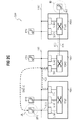
- FIG. 1 shows a communication system CSY with a section of functional components essential to the invention.
- An essential component of the communication system CSY are node units in the form of a first communication device PBX1, a second communication device PBX2 and a third communication device PBX3.
- the communication devices PBX1, PBX2, PBX3 work internally according to a time-slot-oriented switching principle - often referred to in the professional world as »Time Division Multiplex «, TDM designated - and therefore have a corresponding respective switching network TDM1, TDM2, TDM3.
- the communication devices PBX1, PBX, PBX3 are respectively with a circuit switching switching network TDM1, TDM2, TDM3 designed and in each case and with each other with a package-oriented Network connected.
- the first and the second communication device PBX1, PBX2 are with a first packet-oriented network segment LAN1 connected.
- the first packet-oriented network segment LAN1 is alternatively as Intranet, company network, as domain of a larger network or even part of a worldwide network Data network such as the so-called World Wide Web, WWW, designed.
- the third communication device PBX3 is at a second packet-oriented network segment LAN2 connected.
- the configuration of the second packet-oriented network segment LAN2 is the same for the first packet-oriented network segment LAN1 said.
- the first communication device PBX1 is connected via a connection board TB1 with the first packet-oriented network segment LAN1 connected.
- the second communication device PBX2 via a second connection module TB2 with the first packet-oriented network segment LAN1 connected.
- connection assemblies TB1, TB2 of the corresponding communication devices PBX1, PBX2 serve an exchange of packet-oriented Communication data between the two communication devices PBX1, PBX2 via the packet-oriented Network segment LAN1 and count as the communication devices PBX1, PBX2, PBX3 to the category of node units.
- the second communication device PBX2 is the third Communication device PBX3 via a trunk line TRK connected. Unlike a connection via the connection modules TB1, TB2 over the first packet-oriented Network segment LAN1 is on a transmission over the trunk line TRK between the second communication device PBX2 and the third communication device PBX3 a line-oriented Cross connection between both communication devices PBX2, PBX3 provided.
- a first VoIP communication terminal IPP1 is over the first packet-oriented network segment LAN1 and via a first subscriber line module SLM1.1 the first communication device PBX1 having the first communication direction PBX1 connected.
- a second VoIP communication terminal IPP2 is over the first packet-oriented network segment LAN1 and one second subscriber line subassembly SLM1.2 the first communication device PBX1 with the first communication device PBX1 connected.
- a third VoIP communication terminal IPP3 over the first packet-oriented network segment LAN1 with a second subscriber line module SLM2 with the second communication device PBX2 connected.
- Another, fourth VoIP communication terminal IPP4 is via the second packet-oriented network segment LAN2 with a third subscriber line module SLM3 the third Communication device PBX3 connected.
- Another communication terminal ANP is with the third Communication device PBX3 connected line-oriented. It is in this communication terminal ANP example to an analog telephone.
- the subscriber line modules SLM1.1, SLM1.2, SLM2, SLM3 lead a bidirectional conversion between a direction the VoIP communication terminals take place packet-oriented Transmission and one inside the communication devices PBX1, PBX2, PBX3 conduction-oriented Transmission by.
- the subscriber line modules SLM1.1, SLM1.2 are line-oriented with the first switching field TDM1 inside the first communication device PBX1 connected. In appropriate Way are the second subscriber line module SLM2 with the second switching matrix TDM2 as part of the second communication device PBX2 and the third subscriber line module SLM3 with the third switching matrix TDM3 the third communication device PBX3 internally connected.
- the line-oriented communication terminal ANP is a conversion between previously described packet-oriented and circuit-switched communication data not provided.
- the third communication device PBX3 also via a - Not shown - subscriber line module takes place, is a direct one in favor of a comprehensible representation - i. without provision of a conversion - line - oriented Connection of the communication device ANP with the third Coupling field TDM3 shown in the drawing.
- Fig. 2A shows a structure diagram for schematic representation a transmission of communication data in a first Application.
- this first use case becomes a primary communication connection between a calling one Subscriber A at the first communication terminal IPP1 to a called subscriber B at the third VoIP communication terminal IPP3 built.
- the primary communication connection is based on the first VoIP communication terminal IPP1 via a first connection path RA1 to the first subscriber line module SLM1.1 the first communication device PBX1 constructed.
- the first subscriber line module SLM1.1 packet-oriented Communication data of the first VoIP communication terminal IPP1 in line-oriented communication data converted and a first switching matrix TDM1 the supplied to the first communication device PBX1.
- the first communication device PBX1 becomes an intermediary due to the communication data Communication participants determined and accordingly established further connection paths.
- the third VoIP communication terminal to be called is called from another, the second communication device PBX2 managed.
- the coupling field TDM1 After leaving the coupling field TDM1 will connect the communication on one second connection path RA2, via the first connection module TB1 and the first packet-oriented network segment LAN1, led to the second communication device PBX2.
- the second connection path RA2 is via a second Connection module TB2 of the second communication device PBX2, again with bidirectional conversion between packet-oriented and circuit-switched communication data he follows. After this conversion, the connection path becomes further led to the second switching matrix TDM2, in which a line-oriented exchange to the second Subscriber module SLM2 takes place.
- the second participant module SLM2 become the line-oriented communication data again converted into packet-oriented communication data and via the third connection path RA3 or the first packet-oriented network segment LAN1 to the third VoIP communication terminal IPP3 and thus to the called subscriber B through.
- the routing or conversion of the so far in the direction from the calling to the called party A, B described Communication data is in the reverse direction in an analogous way.
- connection paths RA1, RA2, RA3 is a user data exchange between the calling party A and the called party Subscriber B on this connection path.
- On the primary connection path be communication data - including the Payload - a total of six times between a packet-oriented and a wire-oriented format.
- DMC Direct Media Connection
- the SIP standard the H.323 standard or other protocols for providing a transmission of communication data in packet-oriented networks - »Voice over IP «, or VoIP - approachable.
- SIP Session Initiation Protocol
- IETF Internet Engineering Task Force
- the H.323 standard is an international ITU-T standard (International Telecommunication Union - Telecommunication Standardization Sector) for voice, data and video communication about packet-oriented networks that require interoperability the manufacturer products with each other guaranteed.
- ITU-T International Telecommunication Union - Telecommunication Standardization Sector
- the secondary compound DMC-A is in a general case from as close as possible on the part of the calling subscriber A lying node unit or communication unit to a as close as possible to pages of called party B. Communication unit or node unit out.
- Subscriber A, B associated communication terminals IPP1, IPP3 over a valid addressing date, i.e., they are from the first packet-oriented network segment LAN1 of Any communication partner aware of their Network address accessible.
- the secondary connection DMC-A After the later to be described in detail construction of the secondary connection DMC-A send and receive the endpoints - i. the first and the third VoIP communication terminal IPP1, IPP3 - this secondary connection DMC-A user data exclusively via this secondary compound DMC-A, while on the primary connection involving the first and second communication means PBX1, PBX2 and the connection paths RA1, RA2, RA3 no longer transmit user data become.
- this primary connection will be in progress maintain the secondary connection DMC-A, if necessary, e.g. one initiated by the calling party Consultation, agency services or features the communication facilities PBX1, PBX2 claim to be able to.
- Fig . 2B shows a structure diagram for the schematic representation of a transmission of communication data in a second application.
- This second application differs from the aforementioned first use case essentially by the fact that the called party B this time is located at the fourth VoIP communication terminal IPP4 controlled by the third communication device PBX3.
- the third communication device is PBX3 with the second packet-oriented network segment LAN2 connected, it is therefore due to this logical segmentation and respective management by the communication devices PBX1, PBX2, PBX3 no packet-oriented connection between the third communication device PBX3 and the first communication device PBX1 via a common - Not shown - provided network.
- a third connection path RB3 is done in contrast to the first application over the trunk line TRK and thus in a line-oriented Way to the third switching matrix TDM3 of the third Communication device PBX3.
- the primary connection is ongoing in the further via a fourth connection path RB4 of the third subscriber line module SLM3 on the second packet-oriented network segment LAN2 to the fourth VoIP communication terminal IPP4.
- LAN1, LAN2 are these network segments LAN1, LAN2 not physically separated.
- the Division into individual network segments or domains corresponds an administrative allocation to the individual communication devices PBX1, PBX2, PBX3 where below At any time it is assumed that one without participation the communication devices PBX1, PBX2, PBX3 taking place Connection between communication endpoints between the different network segments LAN1, LAN2 via a common - Not shown - build network is.
- the primary compound described above secondary connection DMC-B is due to the packet-oriented Connection of the participants VoIP communication terminals IPP1, IPP4 directly between the mentioned communication terminals IPP1, IPP4.
- Fig. 2C shows a structural diagram for schematic representation a transmission of communication data in a third Application.
- the called is Subscriber B is located at a communication terminal ANP, which does not have a valid addressing date has, the communication terminal ANP of the called party
- B is an analog phone.
- the secondary compound DMC-C goes in this case again from the calling party A, but ends at the second connection board TB2, i. the node unit, which along the primary connection closest to the one called Subscriber B lying node unit with a valid Addressing date is.
- the built up before the secondary connection and parallel to this held primary connection is made from the calling Subscriber A via his assigned VoIP communication terminal IPP1 via a first connection path RC1 the first subscriber line module SLM1.1 the first communication device PBX1, via its first switching matrix TDM1 to the first connection module TB1 and continue via a second connection path RC2 from the first connection module TB1 to the second connection module TB2 of the second Communication device PBX2, from where they over the second switching matrix TDM2 on the trunk line TRK on the third switching matrix TDM3 of the third communication device PBX3 and finally via a connecting line the communication terminal ANP achieved.
- the communication devices PBX1, PBX2, PBX3 and their Local loop modules SLM1.1, SLM1.2, SLM2, SLM3 and their Connection modules TB1, TB2 are in accordance with the language this description as node units with a to consider the valid addressing date, i.e., each circuit-oriented packet-oriented-converting node unit is characterized by a valid addressing date.
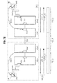
- Fig. 3 shows a communication system with respect to the previous figures changed structure to the schematic Illustration of an efficient design of a secondary Connection.
- the communication system comprises several communication units, in detail, a first VoIP communication terminal IPPA, a second VoIP communication terminal IPPB, a third VoIP communication terminal IPPC, a fourth VoIP communication terminal IPPD, a fifth VoIP communication terminal IPPE, a sixth VoIP communication terminal IPPF and a first communication terminal ANPA and a second one Communication terminal ANPB.
- the last-mentioned communication terminals ANPA, ANPB do not have a valid addressing date and are for example as analog telephones designed.
- the communication system further comprises four partially with each other connected communication devices PBXA, PBXB, PBXC, PBXD.
- the communication devices PBXA, PBXB, PBXC, PBXD operate on a timeslot-oriented
- the principle of mediation - in the professional world often as »Time Division Multiplex «, TDM denotes - and dispose accordingly via a corresponding switching network.
- TDM time Division Multiplex
- the first and the second VoIP communication terminal IPPA, IPPB are via a first switch SWA with the first Communication device connected.
- the fourth and the fifth VoIP communication terminal IPPD, IPPE via a second switch SWD with the fourth communication device PBXD connected.
- the two switch units SWA, SWD each have one valid addressing date and are also as node units consider.
- the connection of the first switch SWA takes place with the associated first communication device PBXA for example via a - not shown - package-oriented Network with one in the first communication device PBXA integrated host switch HSA.
- the connection of the second switch SWD with the fourth communication device PBXD via a second Host Switch HSD.
- a e.g. packet-oriented cross-connection between the first and the second communication device PBXA, PBXB takes place via the first connection module TB-A or via the second Connection assembly TB-B, these connection assemblies TB-A, TB-B in the respective communication facilities PBXA, PBXB are integrated.
- a third connection module TB-C of the third communication device PBXC connects them to a fourth interconnect board TB-D of the fourth communication device PBXD.
- the two switch units SWA, SWD and their connected Host Switch HSA, HSD are like the connection boards TB-A, TB-B, TB-C, TB-D as node units in the sense of before to look at.
- FIG. 3 several possible embodiments of a secondary Connection DMC between the first VoIP communication terminal IPPA and the fourth VoIP communication terminal IPPD shown.
- IPPD IP-to-Network Interface
- the determination of the entry and exit nodes based on the valid Addressing data occurs during connection setup the primary connection.
- the secondary connection advantageously proceeds from an exit node - i. from the called communication unit or one arranged along the primary link last node unit with a valid addressing date - to the entry node - i. to the calling communication unit or to one arranged along the primary link first node unit with a valid addressing date.
- any mixed communication systems arise while in Fig. 3 different ways of Span of the secondary compound DMC.
- the others in Fig. 3 illustrated embodiments of FIG. 3 relate to cases in those outer communication units and node units do not have a valid address date in which the Span of the secondary connection DMC so accordingly is smaller.
- the secondary connection DMC starts at the first switch SWA, which is thus an entry-level node. Accordingly, the ends secondary connection DMC on the fourth switch SWD - exit node - in the event that the called fifth VoIP communication terminal IPPE does not have a valid addressing date features.
- the VoIP communication terminals IPPA, IPPB, IPPC, IPPD, IPPE, IPPF each have a valid addressing date.
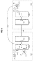
- FIG. 4 shows a structure diagram for the schematic representation of a transmission of communication data in a communication system arranged in several subnetworks.
- the structure diagram of FIG. 4 uses the functional components known from FIG. 3 for the further description.
- DM1 the communication system in a first domain DM1 as well as in a second domain DM2 is structured.
- the domains correspond to DM1, DM2 doing a logical segmentation of the communication system, as in the previous description in a physical expression also as a network segment were designated.
- the following is a connection between a calling Subscriber A on the first communication terminal ANPA and a called party B on the fifth VoIP communication terminal IPPE.
- the Primary connection is a secondary DMC connection between the first connection assembly TB-A of the first communication device PBXA and the fifth VoIP communication terminal IPPE.
- the first connection module TB-A corresponds to the for calling subscriber A nearest node unit with a valid addressing date.
- the communication terminal ANPA itself is, as already mentioned, an analog telephone and therefore does not have a valid addressing date or not about the possibility of a network connection.
- the secondary connection DMC cross-domain is configured, i. from a node unit of the first one Domain DM1 to a communication unit of the second domain DM2.
- FIG. 5 shows the communication system known from FIG. 4 in a second embodiment. While the called subscriber B is once again located at the fifth VoIP communication terminal IPPE, this time the calling subscriber is located at the first VoIP communication terminal IPPA.
- the secondary connection is not directly between the calling subscriber A and the called subscriber B set up can be there because of certain restrictions in the communication system no direct cross-domain connections between the first domain DM1 and the second domain DM2 may or may take place.
- Each node unit checks if the construction of the secondary Connection permissible using this node unit is. In the present case is at the second communication device PBXB as a domain boundary notes that the secondary Do not connect beyond domain boundaries may.
- connection is established in the primary connection "Entry node” including valid addressing data again deleted, thus in subsequent domains again an entry node can be determined.
- the secondary compound is divided into two connecting sections DMC1, DMC2, wherein the first connection section DMC1 between the first VoIP communication terminal IPPA and preceding the second communication unit PBXB Node unit, i. the second connection assembly TB-B, is trained. Consequently, this node unit TB-B also becomes designated as exit node.
- LCR configuration too significant embodiment between the second and the third communication device PBXB, PBXC.
- LCR is one on network specific Rules based connection management according to customer individual Needs such as Voice quality, subscriber-dependent security devices, Cost reasons, bandwidth and / or Availability provided.
- the second connection section DMC2 of the secondary connection begins at the third communication device PBXC following node unit, thus the third connection module TB-C. Consequently, this node unit TB-C also becomes referred to as the entry node. From this entry-level node, the third connection module TB-C, the second takes place Connection section DMC2 of the secondary connection to the called Subscriber B at its fifth VoIP communication terminal IPPA.
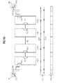
- Fig. 6A is a flowchart showing an exchange of control messages for forming a primary connection.
- a communication connection between a calling party A and a called party Participant B will be established.
- the calling subscriber A is at the first VoIP communication terminal IPPA, the one called Subscriber on the fourth communication terminal IPPD localized.
- the signaling data SGN M support a controller the communication link and a control of features.
- Integrated Services Digital Network In a circuit-oriented ISDN communication system - "Integrated Services Digital Network" - become user data PLD_M via one or more base channels or B channels transfer.
- the signaling information SGN_M is in an ISDN communication system via a so-called Transmit D-channel.
- Destination addresses provide data packets necessary to control the payload and Signaling data PLD_M, SGN_M via the - not shown - to transmit packet-oriented network.
- At the exit from the packet-oriented network becomes in the communication facilities PBXA, PBXB, PBXC, PBXD from the data packets again a continuous data stream composed.
- the procedure begins with the input of an election information or telephone number at the first VoIP communication terminal IPPA by the calling subscriber A. After entering the complete Dialing information is provided by the calling VoIP communication terminal IPPA sent a connection request message SETP, the in the further up to the called VoIP communication terminal IPPD is forwarded.
- This transfer or "transit" the connection request message SETP is accompanied with a modification and enrichment of in the connection request message SETP contained data which drawn by arrows in combination with horizontal lines in the amount of the respective data of the connection request message SETP modifying node unit shown is.
- connection request message SETP is after generation through the first VoIP communication terminal IPPA from the first communication device PBXA received and the second communication device PBXB forwarded. at each propagation of the connection request message SETP is based on configuration data from the primary Connection involved node units, in this case the first communication unit PBXA or the first connection module TB-A checks whether the current node unit a valid addressing date for a possible having secondary connection establishment. Additionally - cf. Fig. 7A to be described later is performed in each node unit a check whether the respective current node unit is a domain boundary.
- the second communication device PBXB initiates upon receipt the connection request message SETP this to the third Communication device PBXC by way of trunking TRK continues.
- the connection request message SETP passes the third communication device PBXC this - following the mentioned modification of the included Data - via the fourth communication device PBXD to the called VoIP communication terminal IPPD on.
- connection request message SETP is the part of the fourth VoIP communication terminal IPPD
- IPPD Upon receipt of the connection request message SETP is the part of the fourth VoIP communication terminal IPPD
- a connection confirmation message CNCT via the fourth switch SWD to the fourth Communication device PBXD and from this to the third Communication device PBXC sent, from which these Connection confirmation message CNCT via the third communication device PBXC over the trunk line TRK to the second communication device PBXB - in one for the connection request message SETP analog way - is passed through.
- the second communication device PBXB becomes the connection acknowledgment message CNCT via the first communication device PBXA and the first one Switch SWA finally to the first VoIP communication terminal IPPA passed on.
- connection request message SETP After the exchange of the last-mentioned connection request message SETP and the connection confirmation message CNCT is the primary link between the first and the second fourth VoIP communication terminal IPPA, IPPD built with it. Based on this primary connection is now a Exchange of user data PLD_M.
- the secondary connection is established after the H.323 or H.225 protocol.
- This direct coupling request message DMC REQ corresponds to a so-called »Fast Connect «message, as in the standard H.225 for a fast data connection is provided.
- a "Fast Connect” message means that a connection between the fourth and the first VoIP communication terminal IPPD, IPPA set off secondary connection, not over - as with the primary Connection necessary - single steps is produced.
- Fig . Fig. 6B shows an exchange of control messages for forming the secondary connection to be established in sequence to the primary connection as described with reference to Fig. 6A.
- a secondary connection DMC is established directly between the two communication end points, ie the fourth and the first VoIP communication terminal IPPD, IPPA.
- CNCT is a direct, advantageous H.323-based connection setup for the secondary Connection feasible.
- the fourth VoIP communication terminal IPPD sends a connection request message SETP S directly to the first VoIP communication terminal IPPA.
- This connection request message SETP S is about - not shown - packet-oriented network transmitted and the first VoIP communication terminal IPPA received.
- the first VoIP communication terminal IPPA then sends one to the network address of the fourth VoIP communication terminal IPPD directed connection acknowledgment message CNCT S, upon receipt of which the secondary connection established is.
- the connection request message SETP S or the Connection confirmation message CNCT S are at an advantageous Use the H.323 protocol according to the H.225 standard arranged tax messages.
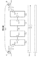
- Fig. 7A is a flowchart illustrating an exchange of control messages for forming a primary connection in a communication system having a predetermined connection path design.
- the communication system is - analogous to the situation according to Description with reference to FIG. 5 and in contrast to the description with reference to FIG. 6A - in a first and a second Domain DM1, DM2 subdivided.
- connection request message SETP is in the present Embodiment between the domains DM1, DM2 line-oriented from the second communication device PBXB via the trunk line TRK to the third communication device PBXC transmitted.
- a line-oriented Trunk line TRK between two node units however, not necessarily be defined as a domain boundary.
- a domain boundary also - e.g. due to special security requirements such as e.g. increased privacy - within a package-oriented Network, such as a secondary connection via a publicly available package-oriented Prevent network.
- connection path design of a node unit namely the second communication device PBXB
- PBXB Due to the connection path design of a node unit, namely the second communication device PBXB, is in the configuration data of this second communication device PBXB notes that the secondary compound does not have over those running after the second communication device PBXB Domain boundary may occur.
- This restriction is placed in a corresponding data field in the connection request message SETP entered and to the next Node unit - in the present embodiment is this is the third communication device PBXC - with a valid address date to instruct them to a renewed starter node valid in its domain DM2 to determine.
- Fig. 7B shows an exchange of control messages for forming the secondary connection to be established in sequence to the primary connection as described with reference to Fig. 7A.
- the secondary connection After the construction of the primary connection becomes a secondary one Connection between the two communication endpoints, i. the fourth and the first VoIP communication terminal IPPD, IPPA established.
- the secondary connection will be this time but with the participation of two packet-oriented connection sections DMC1, DMC2 and another line-oriented Section built on the trunking TRK.
- the Package-oriented connection sections DMC1, DMC2 are included autonomous and independent of each other, controlled by the respective entry and exit nodes in the respective domain DM1, DM2 formed.
- a first entry node of the secondary connection in this Embodiment is the first VoIP communication terminal IPPA whose addressing date - especially IP address - in the direction of the connection request message shown in Fig. 6A SETP is transmitted.
- This transmission of the Addressing date of the first entry node takes place until to a transit node at which a restriction with respect to a Connection route design - domain boundary - in its configuration data is noted.
- This transit node corresponds the second connection module TB-B of the second Communication device PBXB as the boundary of the first domain DM1.
- the transit node becomes the first exit node of a first connection section DMC1 of the secondary connection marked and the addressing date in the - shown in Fig. 6A - Connection request message SETP by the Exit node, the second connection module TB-B, as for the following second domain DM2 not claimed.
- An entry node of the secondary connection in the second Domain DM2 is the third interconnect TB-C of the third Communication device PBXC, whose addressing date - In particular IP address - in the direction of that shown in Fig. 6A Connection request message SETP transmitted becomes.
- This transmission of the addressing date of the second Entry node is up to the "B-side" destination, i. the fourth VoIP communication terminal IPPD.
- the confirmation message CNCT is from this in the second domain DM2 between the exit node there the fourth VoIP communication terminal IPPD and the entry point there - the third connection assembly TB-C - after a replacement of a second secondary Connection request message SETP_S2 and a second secondary connection acknowledgment message CNCT_S2 a packet-oriented DMC2 or "connecting section" of the secondary Connection established.
- IPPD exchanged user data are called packet-oriented User data PLD S on the packet-oriented connections DCM1, DCM2 and as a line-oriented data stream PLD_M exchanged the trunk line TRK.
- the secondary Connection always from the exit node - i. from the called Communication unit or from one along the primary Connection arranged last node unit with a valid addressing date - to the entry node - i. from the calling communication unit or one along the primary connection arranged first node unit with a valid addressing date - done.
- the device is carried out the secondary connection in an analogous way from the entry node to the exit node.
Applications Claiming Priority (2)
| Application Number | Priority Date | Filing Date | Title |
|---|---|---|---|
| DE10354947A DE10354947A1 (de) | 2003-11-25 | 2003-11-25 | Verfahren zur Übermittlung von Kommunikationsdaten in einem Kommunikationssystem |
| DE10354947 | 2003-11-25 |
Publications (3)
| Publication Number | Publication Date |
|---|---|
| EP1536610A2 true EP1536610A2 (fr) | 2005-06-01 |
| EP1536610A3 EP1536610A3 (fr) | 2006-05-10 |
| EP1536610B1 EP1536610B1 (fr) | 2008-04-23 |
Family
ID=34442283
Family Applications (1)
| Application Number | Title | Priority Date | Filing Date |
|---|---|---|---|
| EP04104643A Active EP1536610B1 (fr) | 2003-11-25 | 2004-09-24 | Procédé pour la transmission de données dans un système de communication |
Country Status (4)
| Country | Link |
|---|---|
| US (1) | US7701927B2 (fr) |
| EP (1) | EP1536610B1 (fr) |
| CN (1) | CN100508526C (fr) |
| DE (2) | DE10354947A1 (fr) |
Families Citing this family (6)
| Publication number | Priority date | Publication date | Assignee | Title |
|---|---|---|---|---|
| ATE480071T1 (de) * | 2001-09-20 | 2010-09-15 | Nokia Siemens Networks Gmbh | Verkehrsbegrenzung mittels zulässigkeitsprüfung für ein paketorientiertes verbindungsloses netz mit qos niveau übertragung |
| DE102005001257A1 (de) | 2005-01-11 | 2006-07-20 | Siemens Ag | Verfahren zur Übermittlung von Kommunikationsdaten |
| EP1841161B1 (fr) * | 2006-03-30 | 2008-05-28 | Siemens Aktiengesellschaft | Procédé pour la transmission sécurisée de données utiles |
| EP1850551B8 (fr) * | 2006-04-28 | 2016-11-23 | Unify GmbH & Co. KG | Méthode et appareils pour établir une communication dans un réseau orienté paquet |
| US7693031B2 (en) * | 2007-01-09 | 2010-04-06 | Futurewei Technologies, Inc. | Method and apparatus for achieving system acquisition and other signaling purposes using the preamble in an OFDM based communications system |
| US9160780B2 (en) * | 2011-12-30 | 2015-10-13 | International Business Machines Corporation | System and method for establishing a voice over IP session |
Citations (1)
| Publication number | Priority date | Publication date | Assignee | Title |
|---|---|---|---|---|
| US20020141386A1 (en) * | 2001-03-29 | 2002-10-03 | Minert Brian D. | System, apparatus and method for voice over internet protocol telephone calling using enhanced signaling packets and localized time slot interchanging |
Family Cites Families (20)
| Publication number | Priority date | Publication date | Assignee | Title |
|---|---|---|---|---|
| US5185742A (en) * | 1990-12-31 | 1993-02-09 | At&T Bell Laboratories | Transparent signaling for remote terminals |
| US5764639A (en) * | 1995-11-15 | 1998-06-09 | Staples; Leven E. | System and method for providing a remote user with a virtual presence to an office |
| US5905776A (en) * | 1996-04-04 | 1999-05-18 | Siemens Information And Communication Networks, Inc. | System and method of co-ordinating communications for telecommuters |
| US6134235A (en) * | 1997-10-08 | 2000-10-17 | At&T Corp. | Pots/packet bridge |
| US6359892B1 (en) * | 1997-11-04 | 2002-03-19 | Inventions, Inc. | Remote access, emulation, and control of office equipment, devices and services |
| US20060002381A1 (en) * | 1997-12-09 | 2006-01-05 | Michael Socaciu | Signaling for Internet end stations |
| US6907034B1 (en) * | 1999-04-08 | 2005-06-14 | Intel Corporation | Out-of-band signaling for network based computer session synchronization |
| US20020009071A1 (en) * | 1999-05-06 | 2002-01-24 | Erez Yaary | Communication system and a method for performing telephone calls |
| US6754180B1 (en) * | 1999-12-15 | 2004-06-22 | Nortel Networks Limited | System, method, and computer program product for support of bearer path services in a distributed control network |
| KR100338683B1 (ko) * | 1999-12-29 | 2002-05-30 | 정 데이비드 | 통합 아이피 콜 라우팅 시스템 |
| US7254832B1 (en) * | 2000-08-28 | 2007-08-07 | Nortel Networks Limited | Firewall control for secure private networks with public VoIP access |
| US20020114320A1 (en) * | 2001-02-22 | 2002-08-22 | Ogren Eric K. | Method and system for providing multiple packet connections for a circuit connection across a circuit-to-packet interworking unit |
| US6700884B2 (en) * | 2001-06-28 | 2004-03-02 | Emerson, Iii Harry E. | Integrating the Internet with the public switched telephone network |
| JP3660285B2 (ja) * | 2001-08-30 | 2005-06-15 | 富士通株式会社 | 通信制御方法、中継方法及び中継装置 |
| DE10144356B4 (de) * | 2001-09-10 | 2005-08-04 | Siemens Ag | Verfahren zur Leitweglenkung von Datenpaketen |
| AU2002301409B2 (en) * | 2001-10-13 | 2003-11-06 | Samsung Electronics Co., Ltd. | Internet protocol telephony exchange system and call control method thereof |
| US7639601B2 (en) * | 2002-07-05 | 2009-12-29 | Nortel Networks Limited | Methods and apparatus for data communication |
| US20040008837A1 (en) * | 2002-07-12 | 2004-01-15 | Nortel Networks Limited | Combining multimedia services with traditional telephony services in a public branch exchange |
| US6768726B2 (en) * | 2002-08-06 | 2004-07-27 | Motorola, Inc. | Method and apparatus for effecting a seamless handoff between IP connections |
| US7646761B2 (en) * | 2002-10-01 | 2010-01-12 | Nortel Networks Limited | Integrating multimedia capabilities with legacy networks |
-
2003
- 2003-11-25 DE DE10354947A patent/DE10354947A1/de not_active Ceased
-
2004
- 2004-09-24 DE DE502004006899T patent/DE502004006899D1/de active Active
- 2004-09-24 EP EP04104643A patent/EP1536610B1/fr active Active
- 2004-11-09 US US10/984,711 patent/US7701927B2/en active Active
- 2004-11-25 CN CNB2004100917996A patent/CN100508526C/zh not_active Expired - Fee Related
Patent Citations (1)
| Publication number | Priority date | Publication date | Assignee | Title |
|---|---|---|---|---|
| US20020141386A1 (en) * | 2001-03-29 | 2002-10-03 | Minert Brian D. | System, apparatus and method for voice over internet protocol telephone calling using enhanced signaling packets and localized time slot interchanging |
Non-Patent Citations (1)
| Title |
|---|
| ROSENBERG DYNAMICSOFT H SALAMA CISCO SYSTEMS M SQUIRE HATTERAS NETWORKS J: "Telephony Routing over IP (TRIP); rfc3219.txt" IETF STANDARD, INTERNET ENGINEERING TASK FORCE, IETF, CH, Januar 2002 (2002-01), XP015008998 ISSN: 0000-0003 * |
Also Published As
| Publication number | Publication date |
|---|---|
| US20050111459A1 (en) | 2005-05-26 |
| CN1622554A (zh) | 2005-06-01 |
| US7701927B2 (en) | 2010-04-20 |
| DE502004006899D1 (de) | 2008-06-05 |
| CN100508526C (zh) | 2009-07-01 |
| DE10354947A1 (de) | 2005-06-30 |
| EP1536610A3 (fr) | 2006-05-10 |
| EP1536610B1 (fr) | 2008-04-23 |
Similar Documents
| Publication | Publication Date | Title |
|---|---|---|
| EP1193919B1 (fr) | Procédé pour établir une connection entre un terminal d'un réseau de communication et une destination de connection externe au réseau, et dispositifs pour la réalisation du procédé | |
| DE60014234T2 (de) | System und Verfahren zum Ermöglichen von Fehlertolerante Systeme | |
| EP1712060B1 (fr) | Procede de negociation de proprietes supports dans un resau ip | |
| EP1449388A2 (fr) | Procede pour mettre a disposition des caracteristiques de puissance pour des liaisons de rechange de liaisons primaires | |
| EP1211878A2 (fr) | Méthode et appareil de renvoi d'appel par un représentant dans un système de communication | |
| EP1492300A1 (fr) | Procédé et arrangement pour l'accès à un premier terminal d'un premier réseau de transmissions depuis un noeud de communication d'un deuxième réseau de transmissions | |
| EP1665756A1 (fr) | Interfonctionnement de protocoles dans des reseaux multimedia hybrides | |
| EP1536610B1 (fr) | Procédé pour la transmission de données dans un système de communication | |
| DE60302840T2 (de) | Verfahren zur Optimierung einer bestehenden Übertragung in einem Privatnetz über zwei Sub-Netzwerke mit QSIG und SIP Protokoll | |
| EP1207667B1 (fr) | Procédé et système de communication pour l'établissement d'une liaison H.323 ou SIP à partir d'un réseau source vers une destination externe | |
| DE10241202A1 (de) | Verfahren und Anordnungen zur Kommunikation zwischen einem leitungsvermittelten Kommunikationsnetz und mehreren VoIP-Netzwerkdomänen | |
| EP1841161B1 (fr) | Procédé pour la transmission sécurisée de données utiles | |
| EP1292075B1 (fr) | Méthode de direction d'itinéraire de paquets | |
| WO2003053074A1 (fr) | Procede de fourniture de services rtpc / rnis dans des reseaux de la prochaine generation | |
| DE10226901B3 (de) | Verfahren zur Verbindungssteuerung in einem paketorientierten Kommunikationsnetz sowie Anordnungen zu seiner Durchführung | |
| DE10145758A1 (de) | Verfahren und Anordnung zur Vermittlung einer Verbindung | |
| EP1513312B1 (fr) | Téléphonie Vidéo multimédia | |
| EP1661363B1 (fr) | Procede destine a supporter la caracteristique de fourniture du nom pour des reseaux tdm/architectures de communication sip centrex mixtes | |
| EP1269767B1 (fr) | Traitement de donnees de signalisation et de commande de connexions d'abonnes d'un reseau de communication a commutation de paquets | |
| EP2469822B1 (fr) | Intégration ordinateur-téléphone dans laquelle les ordinateurs sont connectés par l'intermédiaire d'un serveur de présence | |
| EP1214862B1 (fr) | Systeme de communication | |
| EP1077566A2 (fr) | Transfer de parole sans interruption via liaisons IP dans un reseau mobile à protocol IP en utilisant des caractéristiques de conférence des protocols du control des séssions multimédia | |
| DE102004036816B4 (de) | Netzknotenelement zum Einsatz in einem heterogenen Kommunikationssystem | |
| DE10333137A1 (de) | Kommunikationsendgerät mit zwei Schnittstellenstrukturen | |
| WO2004032474A1 (fr) | Unite de commande integree |
Legal Events
| Date | Code | Title | Description |
|---|---|---|---|
| PUAI | Public reference made under article 153(3) epc to a published international application that has entered the european phase |
Free format text: ORIGINAL CODE: 0009012 |
|
| AK | Designated contracting states |
Kind code of ref document: A2 Designated state(s): AT BE BG CH CY CZ DE DK EE ES FI FR GB GR HU IE IT LI LU MC NL PL PT RO SE SI SK TR |
|
| AX | Request for extension of the european patent |
Extension state: AL HR LT LV MK |
|
| PUAL | Search report despatched |
Free format text: ORIGINAL CODE: 0009013 |
|
| AK | Designated contracting states |
Kind code of ref document: A3 Designated state(s): AT BE BG CH CY CZ DE DK EE ES FI FR GB GR HU IE IT LI LU MC NL PL PT RO SE SI SK TR |
|
| AX | Request for extension of the european patent |
Extension state: AL HR LT LV MK |
|
| 17P | Request for examination filed |
Effective date: 20060619 |
|
| 17Q | First examination report despatched |
Effective date: 20060823 |
|
| AKX | Designation fees paid |
Designated state(s): DE FR GB IT SE |
|
| GRAP | Despatch of communication of intention to grant a patent |
Free format text: ORIGINAL CODE: EPIDOSNIGR1 |
|
| GRAS | Grant fee paid |
Free format text: ORIGINAL CODE: EPIDOSNIGR3 |
|
| GRAA | (expected) grant |
Free format text: ORIGINAL CODE: 0009210 |
|
| RAP1 | Party data changed (applicant data changed or rights of an application transferred) |
Owner name: SIEMENS ENTERPRISE COMMUNICATIONS GMBH & CO. KG |
|
| AK | Designated contracting states |
Kind code of ref document: B1 Designated state(s): DE FR GB IT SE |
|
| REG | Reference to a national code |
Ref country code: GB Ref legal event code: FG4D Free format text: NOT ENGLISH |
|
| REF | Corresponds to: |
Ref document number: 502004006899 Country of ref document: DE Date of ref document: 20080605 Kind code of ref document: P |
|
| REG | Reference to a national code |
Ref country code: SE Ref legal event code: TRGR |
|
| ET | Fr: translation filed | ||
| PLBE | No opposition filed within time limit |
Free format text: ORIGINAL CODE: 0009261 |
|
| STAA | Information on the status of an ep patent application or granted ep patent |
Free format text: STATUS: NO OPPOSITION FILED WITHIN TIME LIMIT |
|
| 26N | No opposition filed |
Effective date: 20090126 |
|
| REG | Reference to a national code |
Ref country code: DE Ref legal event code: R082 Ref document number: 502004006899 Country of ref document: DE Representative=s name: FRITZSCHE, THOMAS MICHAEL, DIPL.-CHEM. DR.RER., DE |
|
| REG | Reference to a national code |
Ref country code: DE Ref legal event code: R082 Ref document number: 502004006899 Country of ref document: DE Representative=s name: FRITZSCHE, THOMAS MICHAEL, DIPL.-CHEM. DR.RER., DE Effective date: 20131112 Ref country code: DE Ref legal event code: R081 Ref document number: 502004006899 Country of ref document: DE Owner name: UNIFY GMBH & CO. KG, DE Free format text: FORMER OWNER: SIEMENS ENTERPRISE COMMUNICATIONS GMBH & CO. KG, 81379 MUENCHEN, DE Effective date: 20131112 Ref country code: DE Ref legal event code: R082 Ref document number: 502004006899 Country of ref document: DE Representative=s name: FRITZSCHE PATENTANWAELTE, DE Effective date: 20131112 |
|
| REG | Reference to a national code |
Ref country code: FR Ref legal event code: CD Owner name: UNIFY GMBH & CO. KG, DE Effective date: 20150209 |
|
| PGFP | Annual fee paid to national office [announced via postgrant information from national office to epo] |
Ref country code: SE Payment date: 20150922 Year of fee payment: 12 |
|
| PGFP | Annual fee paid to national office [announced via postgrant information from national office to epo] |
Ref country code: IT Payment date: 20150925 Year of fee payment: 12 |
|
| REG | Reference to a national code |
Ref country code: FR Ref legal event code: PLFP Year of fee payment: 13 |
|
| REG | Reference to a national code |
Ref country code: DE Ref legal event code: R082 Ref document number: 502004006899 Country of ref document: DE Representative=s name: SCHAAFHAUSEN PATENTANWAELTE PARTNERSCHAFTSGESE, DE Ref country code: DE Ref legal event code: R082 Ref document number: 502004006899 Country of ref document: DE Representative=s name: FRITZSCHE PATENTANWAELTE, DE Ref country code: DE Ref legal event code: R081 Ref document number: 502004006899 Country of ref document: DE Owner name: UNIFY GMBH & CO. KG, DE Free format text: FORMER OWNER: UNIFY GMBH & CO. KG, 81379 MUENCHEN, DE |
|
| PG25 | Lapsed in a contracting state [announced via postgrant information from national office to epo] |
Ref country code: SE Free format text: LAPSE BECAUSE OF NON-PAYMENT OF DUE FEES Effective date: 20160925 |
|
| REG | Reference to a national code |
Ref country code: SE Ref legal event code: EUG |
|
| PG25 | Lapsed in a contracting state [announced via postgrant information from national office to epo] |
Ref country code: IT Free format text: LAPSE BECAUSE OF NON-PAYMENT OF DUE FEES Effective date: 20160924 |
|
| REG | Reference to a national code |
Ref country code: FR Ref legal event code: PLFP Year of fee payment: 14 |
|
| REG | Reference to a national code |
Ref country code: DE Ref legal event code: R082 Ref document number: 502004006899 Country of ref document: DE Representative=s name: SCHAAFHAUSEN PATENTANWAELTE PARTNERSCHAFTSGESE, DE |
|
| REG | Reference to a national code |
Ref country code: DE Ref legal event code: R079 Ref document number: 502004006899 Country of ref document: DE Free format text: PREVIOUS MAIN CLASS: H04L0029060000 Ipc: H04L0065000000 |
|
| PGFP | Annual fee paid to national office [announced via postgrant information from national office to epo] |
Ref country code: GB Payment date: 20230921 Year of fee payment: 20 |
|
| PGFP | Annual fee paid to national office [announced via postgrant information from national office to epo] |
Ref country code: FR Payment date: 20230918 Year of fee payment: 20 Ref country code: DE Payment date: 20230919 Year of fee payment: 20 |