EP1269767B1 - Traitement de donnees de signalisation et de commande de connexions d'abonnes d'un reseau de communication a commutation de paquets - Google Patents
Traitement de donnees de signalisation et de commande de connexions d'abonnes d'un reseau de communication a commutation de paquets Download PDFInfo
- Publication number
- EP1269767B1 EP1269767B1 EP01935952A EP01935952A EP1269767B1 EP 1269767 B1 EP1269767 B1 EP 1269767B1 EP 01935952 A EP01935952 A EP 01935952A EP 01935952 A EP01935952 A EP 01935952A EP 1269767 B1 EP1269767 B1 EP 1269767B1
- Authority
- EP
- European Patent Office
- Prior art keywords
- subscriber
- packet
- network element
- network
- interface
- Prior art date
- Legal status (The legal status is an assumption and is not a legal conclusion. Google has not performed a legal analysis and makes no representation as to the accuracy of the status listed.)
- Expired - Lifetime
Links
Images


Classifications
-
- H—ELECTRICITY
- H04—ELECTRIC COMMUNICATION TECHNIQUE
- H04Q—SELECTING
- H04Q3/00—Selecting arrangements
- H04Q3/0016—Arrangements providing connection between exchanges
- H04Q3/0025—Provisions for signalling
-
- H—ELECTRICITY
- H04—ELECTRIC COMMUNICATION TECHNIQUE
- H04M—TELEPHONIC COMMUNICATION
- H04M7/00—Arrangements for interconnection between switching centres
- H04M7/0093—Arrangements for interconnection between switching centres signalling arrangements in networks
Definitions
- the invention relates to a method for processing signaling data and for connection control of subscribers in packet-switched communication networks.
- a subscriber is connected to a packet-switched communication network.
- signaling information is transmitted between a switching entity and the subscriber.
- the invention relates to a network element.
- switching nodes i. Switching centers or switching systems. These switching nodes comprise access groups, so-called peripheral devices, for connecting subscribers or lines, a central computer platform, a message distribution device and further central units, such as e.g. a switch fabric, protocol termination equipment of the No. 7 signaling system, background storage and controls.
- access groups so-called peripheral devices
- message distribution device for connecting subscribers or lines
- message distribution device for connecting subscribers or lines
- further central units such as e.g. a switch fabric, protocol termination equipment of the No. 7 signaling system, background storage and controls.
- the access groups fulfill essential call-processing tasks linked to the voice channels of the access groups. They therefore contain call processing, operational and administrative programs as well as the data information associated with the connection group, such as connection status, signaling, authorizations, telephone numbers, individual characteristics of connection lines and subscriber lines as well as the configuration and configuration of the access group.
- the central computer platform serves for the coordinated control of the connection setup and the disconnection as well as the reaction to administrative and error-related configuration changes.
- the peripheral devices are connected to each other via the message system and to the common computer platform.
- the other central system components provide the switching system of the switching node with special functions, e.g. for the implementation of voice channels, for the processing of signaling protocols, for the realization of operator interfaces or for the storage of mass data.
- the central components of the switching system are designed redundantly, i. e.g. double. If no increased demands are placed on the switching-based availability of the subscribers and the connection lines of the switching system, the connection groups are not executed redundantly. However, if stable connections beyond the failure of a port group are to be available, the port groups will also be designed redundantly.
- the signaling data for subscriber signaling are common to subscriber groups, ie for several subscribers Assistance of a communication channel according to the definition of the used concentrator interface between subscriber concentrator on the one hand and the switch on the other hand bidirectional transfer.
- additional end-to-end packet data (user-to-user signaling) or packet data can be passed on to a packet handler interface for forwarding.
- the user data is usually not brought to an exchange. It is only necessary to bring the user data to an exchange if a subscriber participating in the connection is connected to a conventional circuit-switching communication network, eg a communication network with time-division multiplexing, and thus can not be reached directly via the packet network - see EP-A-0 966 145 , In such a case, conversion of the payload data to match the transmission technique used in the different communication networks is required. Such a conversion is necessary in particular in the case of a transition from a communication network with packet transmission technology to a communication network with time-division-multiplex transmission technology (TDM technology).
- TDM technology time-division-multiplex transmission technology
- This conversion is performed both in the transmission of data of the communication network with time-division multiplex transmission technology to the communication network with packet transmission technology as well as in a transmission of data of the communication network with packet transmission technology to the communication network with time-division transmission technology.
- their user data is preferably exchanged directly via the packet network. In this case, the user data are thus generally not routed via the exchange with the aid of converters or gateways.
- the subscribers in the packet network are not in terms of their hardware a subscriber concentrator or associated with a concentrator interface of an exchange of the circuit-switching communication network.
- the subscribers have neither lines for analog signaling nor a D channel for signaling, which is brought to a fixed, an exchange upstream subscriber concentrator.
- the signaling in connections between subscribers of a packet-switched communication network can not be carried out for voice connections between these subscribers in the prior art with the help of a conventional switching center of the circuit-switched communication network. If connection requests from telephone subscribers of a packet network are processed by means of an exchange or a server providing switching functions, the signaling takes place by means of the packet network, ie the signaling data are transported in a packet-oriented manner.
- Telephone subscribers in a packet-switched communications network are e.g. Subscribers connected to a network based on an Internet Protocol directly or via a dial-up connection.
- the subscriber will also be provided with voice and / or fax services.
- voice and / or fax services should have the same scope of services that conventional telephones and fax machines offer.
- the payload of such a subscriber is transmitted as data packets according to the Internet Protocol, e.g. according to the so-called Transmission Control Protocol / User Datagram Protocol (TCP / UDP).
- TCP / UDP Transmission Control Protocol / User Datagram Protocol
- the transmission of signaling information takes place in the packet-switched communication network by means of signaling packets according to defined standards, such as e.g. H.323, H.225, H.245, H.450 and SIP.
- the transmission of signaling data and the transmission of user data take place on separate transmission paths.
- the user data is fed directly to the other subscriber.
- the user data of an interface unit for conversion are supplied, for example, a media gateway (MG).
- the signaling data are supplied by means of signaling data packets to a switching entity which performs the connection control.
- components such as e.g. Terminals, gateways, gatekeepers and multipoint control units are involved and defined, which are involved in such a connection.
- An H.323 terminal corresponds to the subscriber of the packet-switched communication network.
- Gateways are used when the connection is e.g. must be conducted via a public telephone network or a call partner is a subscriber connected to an exchange of the public telephone network.
- Multipoint Control Units are provided for e.g. Building conference circuits.
- the gatekeeper As a central component of the gatekeeper involved in establishing a connection. This can be regarded as an exchange in the packet-switched communication network.
- the gatekeeper provides functions for its zone, including access control, signaling, connection control and charging. With the help of the gatekeeper also necessary for access to the public telephone network number assignment (E.164) to the valid for the subscriber of the packet-switching communication network participant address takes place.
- E.164 public telephone network number assignment
- the address of the subscriber is the IP address.
- the gatekeeper is thus not an exchange of a public telecommunications network, but a control unit in the IP-based communication network. Such a control unit is eg a server.
- a conventional switching center of a circuit-switching communication network is to carry out the connection control or the processing of signaling data for subscribers of a packet-switched communications network
- the packet-network-specific signaling methods relevant for subscriber signaling must be implemented in the exchange.
- a signaling access to the packet-switching communication network must be implemented in the exchange, and the software-based access to the subscribers of the packet-switching communication network must be ensured.
- the object of the invention is to provide a method and an arrangement, which or simply a network element a circuit-switching communication network for subscriber signaling of subscribers of a packet-switched communication network uses.
- a conventional concentrator interface in the network element e.g. an exchange of a circuit-switched communication network is installed.
- an exchange of a circuit-switched communication network is installed.
- the method according to the invention furthermore makes it possible to exchange signaling data between a subscriber of a packet-switched communications network and an exchange of a circuit-switched communications network.
- the transmission of the user data can thus be controlled by the exchange.
- Billing according to the requirements customary in telecommunication networks is easy to carry out.
- the control can take place both for connections in which the User data are routed through the exchange, as well as for connections in which the user data directly between the participants, eg using the packet-switched communication network, are transmitted.
- the subscriber of the packet-switching communication network is also uniquely addressable for subscribers of circuit-switched communication networks.
- several connections to a subscriber of the packet-switching communications network can be set up at the same time.
- the subscriber of the packet-switching communication network can form a group with other subscribers of the packet-switching communications network and / or with subscribers of the circuit-switching communications network. Members of the group have access to additional services and / or features within the group.
- a group may e.g. a CENTREX group, also known as the CENTREX Business Group.
- the processing of signaling data and the connection control of the subscriber of the packet-switched communication network can be carried out on the basis of the features known for a base connection of a circuit-switching communication network or of a primary multiplex connection of a circuit-switching communication network.
- the exchange can thus provide the subscriber of the packet-switching communications network with service and / or performance features that are possible in circuit-switching communications networks.
- a concentrator interface With the installation and establishment of a concentrator interface in an exchange, data stores with subscriber reference are located in the central units of the exchange as well as in peripheral units of the exchange, as in the connection groups, available. In these data stores properties of the participants are stored, which are assigned to the concentrator interface. Such features include telephone number, type of connection, availability of line characteristics, blocking information, group membership to CENTREX, etc. Furthermore, switching-center resources such as processor capacity, signaling termination capacity and message distribution capacity are provided for the subscribers associated with the concentrator interface.
- the signaling data for subscriber signaling of the subscribers of the packet-switching communication network generated in the peripheral units of the exchange are fed to a packet control unit which, for example, is connected directly to the packet-switched communications network and converts the signaling data for subscriber signaling of the subscribers of the packet-switched communications network into signaling packets of the packet-switched communications network.
- the administration and status changes, eg in case of failure and re-availability, of the concentrator interface for subscribers of the packet-switched communications network are carried out in the same way as in concentrator interfaces to which subscribers of the circuit-switching communications network are connected.
- the function of storing the current accessibility of a packet-based subscriber in the packet network and the assignment of his call processing address, ie his E.164 phone number, to his possibly temporary address in the packet network can be performed by servers upstream of the exchange. At the same time, these servers assume the function of access control (GK-RAS) and the function of a firewall to the packet network.
- GK-RAS access control
- both the connection control of subscribers of the circuit-switching communication network and of subscribers of the packet-switching communication network can be carried out in a connection between the exchange to a circuit-switching and a packet-switched communication network.
- FIG. 1 shows a typical structure of a conventional switching system by means of a block diagram.
- a switching system has a switching network SN (Switching Network), a message distributor MB (Message Buffer), a coordination processor CP (Coordination Processor), controls NC, background memory MD and protocol termination CCNC (eg according to signaling system no. 7).
- These elements of the switching system are to increase the reliability redundant, ie, for example, double executed.
- the switching system also has connection groups LTG (Line / Trunk Group), which are connected to the switching network SN and the message distribution system MB.
- LTG Line / Trunk Group
- connection groups LTG are also referred to as peripheral units of the switching system and serve to connect subscribers and connection lines and to connect concentrator interfaces, with the aid of which, for example, separately arranged connection units can be connected. If no increased demands are placed on the switching-based availability of the subscribers and connection lines of the switching system, the connection groups LTG are not executed redundantly.
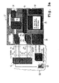
- FIG. 2 shows a concentrator interface 10 and an exchange 12 as well as building units of the exchange.
- the switching center 12 has a message distribution system 14, a switching network 16 and terminal groups 18, 20.
- the concentrator interface 10 has a connection area 24, which is connected to the terminal groups 18, 20 by means of eight PCM links 26a to 26d, 28a to 28d.
- a subscriber line concentrator connected via the concentrator interface 10 is also referred to as an access network (AN).
- AN access network
- the signaling and control channels have e.g. a data transfer capacity of 64 kbit / s and are routed in the PCM links 26a to 26d, 28a to 28d between the port groups 18, 20 and the subscriber line concentrator. If a large signaling and control data volume is to be expected at the concentrator interface 10, the concentrator interface 10 may comprise a plurality of signaling and control channels.
- 10 data memories with subscriber reference are provided for the concentrator interface in the central units of the central office 12 and in the port groups 18, 20.
- the properties of the subscribers connected via this concentrator interface 10 are stored in these data memories.
- switching resources such as e.g. Processor capacity, signaling termination capacity, message transfer capacity for the subscribers connected via the concentrator interface 10.
- the subscribers connectable via the concentrator interface 10 can be subscribers with an ISDN basic access, an ISDN primary rate access or an analog subscriber access. Both main and extension connections are possible. With the help of such a concentrator interface 10, a limited number of participants, eg 2000 subscribers, can be connected due to the assigned connection groups.
- the concentrator interface 10 includes, for example, eight PCM30 links, with a total of eight signaling and control channels included.
- the concentrator interface 10 is an example of a V5.2 interface. For a more detailed functional description Reference is made to the standard ETS 300 347 for this interface.
- FIG. 3 a shows an exchange 12, which has connection groups 18 a, 20 a through which a concentrator interface 10 is controlled.
- a second concentrator interface 44 is activated.
- the terminal groups 18a, 18b, 20a, 20b are connected to the message distribution system 14 of the central office 12.
- the messaging system 14 of the central office 12 is further connected to the switching center 16 of the central office, a communications processor 34 and a protocol terminator 40, e.g. may be a protocol termination means of the signaling system no. 7.
- the message distribution system 14 is further connected to a packet control unit 36.
- the concentrator interface 10 includes eight PCM30 links. Four of the eight PCM30 links each are connected to the connection groups 18a, 20a, of which only two PCM30 links are shown in FIG. 3a.
- the concentrator interface 44 also includes eight PCM links. Of these eight PCM links, four PCM30 links 30, 32 are connected to the terminal groups 18b, 20b, of which only two are also shown.
- the PCM30 links 26, 28 are routed to a media gateway 46.
- the PCM30 links 30, 32 are also routed to the media gateway 46.
- the media gateway 46 provides an interface between the circuit-switched communications network and a packet-switched communications network 50.
- a subscriber 48 is a subscriber to the packet-switched communications network 50.
- the packet-switched communications network 50 is an IP network.
- the subscriber 48 is set up at the concentrator interface 10.
- the coordination processor 34 and other central units of the exchange 12 provide the concentrator interfaces 10, 44, in particular memory areas in the database of the switching center 12, computing capacity and signaling capacity for subscriber signaling, for subscriber administration and for service and maintenance of the concentrator interface 10, 44 and the subscriber lines ready, which are connected via these interfaces 10, 44.
- the user data is supplied from the terminal of the subscriber 48 with the aid of the IP network 50 to the media gateway 46.
- the user 48 transmits the user data as data packets to the media gateway 46.
- the media gateway 46 converts these data packets into data of the circuit-switching communication network of the switching center 12 and transmits them by means of the PCM30 links 26, 28 to the port groups 18a, 20a. These payloads are transmitted by the port groups 18a, 20a by means of unillustrated connections between the port groups 18a, 20a and the switching network 16.
- the switching network 16 switches the connection to the further subscriber, which is set up at the concentrator interface 44.
- the user data of the subscriber 48 are transmitted from the switching network 16 to one of the terminal groups 18b, 20b.
- the PCM30 links 30, 32 these data are transmitted from the port groups 18b, 20b via the concentrator interface 44 to the media gateway 46, which converts these data into data packets which are supplied to the further subscriber with the aid of the IP network 50.
- the transmission of the user data of the other participant in the direction of participants 48 is carried out in the same way vice versa.
- the further subscriber can also be a subscriber of the circuit-switching communication network, which can be reached, for example, via a further connection group 38 of the exchange 12. If the subscriber is a subscriber to a further exchange of the circuit-switching communication network, the data is transmitted between the further exchange and the exchange 12 by means of the circuit-switched communication network.
- the further subscriber can also be another subscriber of the packet-switching communications network, which is connected via the media gateway 46 or another media gateway to the switching center 12 or to another switching center.
- the subscriber signaling signaling data is not transmitted from the port groups 18a, 18b, 20a, 20b to time slots of the PCM links or communication channels routed in the PCM links to the port groups 18a, 18b, 20a, 20b this is known when connecting concentrator interfaces 10, 44 with conventional subscribers.
- the signaling information for subscriber signaling is exchanged via the message distribution system 14 between the port groups 18a, 18b, 20a, 20b and the packet control unit 36.
- the packet control unit 36 takes over the coordination of the control of the media gateway 46 and the implementation of the subscriber signaling of the subscriber 48 to the used in the IP network 50 by the subscriber 48 signaling method H.323.
- the connection between the packet control unit 36 and the media gateway 46 for controlling the media gateway 46 is represented by a dotted line.
- the subscriber signaling of the subscriber 48 takes place via a gatekeeper 42, which is connected to the packet control unit 36.
- the connection between the packet control unit 36 and the gatekeeper 42 is represented by two dashed lines, the subscriber signaling between the packet control unit 36 and the gatekeeper 42 and between the gatekeeper 42 and the subscriber 48 using the H.225 / H.245 standard.
- the gatekeeper 42 provides an access control function and a firewall function.
- FIG. 3b shows a second exchange 22 similar to the exchange 12 shown in FIG. 3a.
- the exchange 22 does not have a switching network for switching payload connections with respect to the switching center 12 of FIG. 3a.
- the subscriber signaling and the connection control takes place with the aid of the exchange 22 in the same manner as has already been described for the exchange 12 of FIG. 3a.
- the switch 22 has a first concentrator interface Vx 58 and a second concentrator interface Vx 60 which, unlike the concentrator interfaces 10 and 44 of FIG. 3, do not include PCM links.
- the user data is transmitted or guided exclusively via the IP network 50.
- FIG. 4 shows an arrangement in which the switching center 12 switches a voice connection between the subscriber 48 and a further subscriber 56. Both the subscriber 48 and the subscriber 56 are connected via the IP network 50.
- the media gateway 46 is connected to the central office 12 via the concentrator interface 10 by means of PCM links.
- a media gateway 54 is connected to the central office 12 via PCM links via a concentrator interface 52. Both media gateways 46, 54 are connected to the IP network 50.
- the user data for the voice connection between the subscriber 48 and the subscriber 56 are transmitted between the subscriber 48 and the media gateway 46 and between the media gateway 54 and the subscriber 56 with the aid of data packets.
- the media gateways 46, 54 convert these data packets into data of a circuit-switching communications network and transmit them via the PCM links between the media gateways 46 and 54 via the interfaces 10 and 52 to the switching center 12.
- the switching network 16 of the switching center 12 switches a connection for transmitting this user data.
- the signaling data for subscriber signaling is exchanged via the message distribution system 14 with the packet control unit 36.
- the packet control unit 36 has in each case a connection to the media gateway 46 and to the media gateway 54, which is indicated in FIG. 4 by dotted lines.
- the packet control unit 36 controls the media gateways 46, 54.
- the subscriber signaling is transmitted from the packet control unit 36 of the switching center 12 to the gatekeeper 42 in an IP-based manner. In Figure 4, this transfer is shown by means of a dashed line.
- the gatekeeper 42 transmits the subscriber signaling data of the subscriber 48 and the subscriber signaling data of the subscriber 56 by means of the IP network 50.
- the signaling information for subscriber signaling is no longer routed via the PCM links of the concentrator interfaces 10, 52.
- the subscriber signaling is rather carried out via the packet control unit 36, which controls both the media gateways 46, 54 and the subscriber signaling to the needs of the participants 48, 56 of the IP network 50, such as H.323 or SIP signaling, converts and and converts the IP-based subscriber signaling in the reverse direction to the signaling standard of the concentrator interface 10, 52 and forwards them to the respective port group.
- the subscribers 46, 48 are introduced as subscribers of a new type. These subscribers can be assigned properties of an ISDN basic access or an ISDN private branch access. However, the subscribers of the packet-switched communications network are identified in the database so that they can only be connected to concentrator interfaces 10, 44, 52, in which the subscriber signaling of the subscribers 46, 48 assigned to them takes place directly via a packet control unit 36.
- subscribers 48, 56 may be provided with main and extension line features.
- concentrator interfaces 10, 44, 52 no conventional participants of the circuit-switching communication network can be connected, as no direct, guided over the time slots of the associated PCM30 links subscriber signaling takes place via these interfaces 10, 44, 52.
- These concentrator interfaces 10, 44, 52 can thus also be referred to as virtual concentrator interfaces.
- these interfaces 10, 44, 52 are also marked, so that no conventional participants of the circuit-switching communication network can be connected to these interfaces 10, 44, 52.
- Both in the configuration of the interfaces 10, 44, 52 and in the setup and configuration of the participants 48, 56 is an administrative review, which ensures that no conventional participants can be connected to the interfaces 10, 44, 52 and that the Subscriber 48, 56 only interfaces 10, 44, 52 are assigned, which support the inventive method for connecting subscribers 48, 56 of a packet-switched communication network 50.
- the routing of the user data stream via the switching center 12 enables voice processing, in particular of tones, of announcements, dialogues and two-tone signals, which can be introduced and / or processed in a conventional manner by the switching center.
- voice processing in particular of tones, of announcements, dialogues and two-tone signals, which can be introduced and / or processed in a conventional manner by the switching center.
- events are used which arise in the switching-active terminal group of the switching center 12 and the switching through of a time slot of the concentrator interface 10, 52 associated PCM path to a subscriber channel of the subscriber 48, 50 relate.
- the beginning and end of such an assignment is transmitted from the port group 18a, 18b, 20a, 20b to the packet control unit 36 and leads here to the appropriate setting of gateway 46, 54 and terminal of the subscriber 48, 50th
- FIG. 5 shows a further arrangement for processing signaling data and for connection control of subscribers 48, 56, which are connected via the IP network 50.
- the user data between the subscriber 48 and the subscriber 56 is not routed via the exchange 12 but is transmitted directly via the IP network 50.
- the media gateways 46 and 54 are not required. It is also possible to dispense with the PCM30 links of the concentrator interface 10 at the port groups 18a, 20a and 20, since no user data is to be transmitted via the port groups 18a, 20a. The same applies to the concentrator interface 52.
- the subscriber 48 of the concentrator interface 10 and the subscriber 56 of the concentrator interface 52 are assigned in the database of the switching center 12. This is indicated by the thin-drawn connection line between the interface 10 and the subscriber 48 and between the interface 52 and the subscriber 56.
- the subscriber signaling of the subscribers 48, 56 takes place as already described in FIG.
- the packet control unit 36 of the switching center 12 also supplies the signaling data to the gatekeeper 42.
- the gatekeeper 42 has the same functionality as the gatekeeper described in the embodiment of FIG.
- the concentrator interfaces 10, 44, 52 and the subscribers 48, 56 are identified in the database of the exchange 12.
- the marking of the concentrator interface 10, 44, 52 allows the software of the terminal groups 18a, 18b, 20a, 20b to dispense with actions that are no longer useful when connecting participants 48, 56 packet-switched communication networks 50.
- the activation of the control and signaling channels of the concentrator interface 10, 44, 52 is prevented.
- the commissioning of the concentrator interfaces 10, 44, 52 associated with PCM sections 26, 28, 30, 32 are prevented, which is required in the present embodiment.
- the central parts of the exchange 12 however, the availability of no longer required functions and the enforcement of no longer required functions is signaled to avoid in particular unwanted or meaningless error responses or to keep the adjustment effort in the central parts of the exchange 12 low.
- essential attributes which are indispensable for the central office 12, but which are not relevant for these concentrator interfaces 10, 44, 52, can be automatically generated by the system on the user interface and thus do not have to be introduced via the operator interface of the central office 12 by an operator.
- control units can be servers, for example.
- the parcel control unit 36 determines the subscriber addresses of the subscriber 48 and the subscriber 56 in the IP network 50 with the aid of this control unit on the basis of the E.164 telephone number, and thus its availability for occupancy by another subscriber, ie for a B-side occupancy , In the case of an A-side occupancy, the implementation of the A-number to the responsible for the subscriber concentrator interface, whereby the A-side switching line responsible connection group is selected.
- the above server function was referred to as GK-RAS in the context of the embodiment of FIGS. 3a and 3b.
- the concentrator interface 10, 44, 52, 58, 60 may comprise SDH links.
Claims (28)
- Procédé pour le traitement de données de signalisation et pour la commande de connexions dans un réseau de communication à commutation de paquets,
dans lequel un réseau de communication à commutation de paquets (50) comprend au moins un abonné (48, 56),
un élément de réseau (12, 22) commande une interface de concentrateur (10, 44, 52, 58, 60) à l'aide d'au moins une unité de connexion (18, 20) et met à disposition des ressources à celle-ci,
des données de signalisation pour la signalisation d'abonné de l'abonné (48, 56) sont transmises entre au moins une unité de commande de paquets (36) de l'élément de réseau (12, 22) et l'unité de connexion (18, 20) de l'élément de réseau (12, 22) par l'intermédiaire d'un système de distribution de messages (14) de l'élément de réseau (12, 22),
les données de signalisation de l'élément de réseau (12, 22) sont converties par l'unité de commande de paquets (36) en paquets de signalisation du réseau de communication à commutation de paquets (50) et vice-versa,
et dans lequel les paquets de signalisation sont transmis entre l'unité de commande de paquets (36) et l'abonné (48, 56). - Procédé selon la revendication 1, caractérisé en ce que l'élément de réseau est un centre de commutation d'un réseau de télécommunication à commutation de circuits.
- Procédé selon l'une quelconque des revendications précédentes, caractérisé en ce que l'abonné (48, 56) est géré et opéré dans l'élément de réseau (12, 22) en tant qu'un abonné (48, 56) connecté à l'aide de l'interface de concentrateur (10, 44, 52, 58, 60) et en ce que les ressources mises à disposition à l'interface de concentrateur (10, 44, 52, 58, 60) sont utilisées pour l'abonné (48, 56).
- Procédé selon l'une quelconque des revendications précédentes, caractérisé en ce que les fonctions d'un branchement principal ou d'un branchement avec postes supplémentaires sont disponibles à l'abonné (48, 56) dans l'élément de réseau (12, 22).
- Procédé selon l'une quelconque des revendications précédentes, caractérisé en ce que l'interface de concentrateur (10, 44, 52, 58, 60) est gérée et opérée en tant qu'interface V5.2, interface TR303, interface V93 et/ou interface V95.
- Procédé selon l'une quelconque des revendications précédentes, caractérisé en ce que l'interface de concentrateur (10, 44, 52, 58, 60) a des liaisons PCM ou des liaisons SDH pour la transmission bidirectionnelle de données utiles vers une unité d'interface (46, 54) qui convertit des données utiles entre un format usuel dans le réseau de communication à commutation de paquets (50) et un format usuel dans le réseau de communication à commutation de circuits.
- Procédé selon la revendication 6, caractérisé en ce que l'unité d'interface est une passerelle média (46, 54) qui convertit les données utiles de manière bidirectionnelle entre le format de paquets et le format TDM.
- Procédé selon la revendication 6 ou 7, caractérisé en ce que la commande de l'unité d'interface (46, 54) est réalisée par l'intermédiaire de groupes de connexion (18, 20) de l'élément de réseau (12), qui commandent l'interface de concentrateur (10, 44, 52, 58, 60).
- Procédé selon l'une quelconque des revendications précédentes, caractérisé en ce que l'interface de concentrateur (10, 44, 52, 58, 60) est identifiée dans une base de données de l'élément de réseau (12, 22) en tant qu'interface de concentrateur (10, 44, 52, 58, 60) pour le raccordement d'abonnés (48, 56) du réseau de communication à commutation de paquets (50).
- Procédé selon l'une quelconque des revendications précédentes, caractérisé en ce que l'abonné (48, 56) est géré dans une base de données de l'élément de réseau (12, 22) en tant qu'abonné (48, 56) du réseau de communication à commutation de paquets (50).
- Procédé selon la revendication 10, caractérisé en ce que seulement des abonnés (48, 56), qui sont des abonnés (48, 56) du réseau de communication à commutation de paquets (50), peuvent être affectés à l'interface de concentrateur (10, 44, 52, 58, 60) destinée au raccordement d'abonnés (48, 56) du réseau de communication à commutation de paquets (50).
- Procédé selon l'une quelconque des revendications précédentes, caractérisé en ce que des fonctions de l'interface de concentrateur (10, 44, 52, 58, 60) destinée au raccordement d'abonnés (48, 56) du réseau de communication à commutation de paquets (50), qui ne sont pas nécessaires, sont désactivées et/ou en ce que des messages de ces fonctions sont supprimés dans l'élément de réseau (12, 22).
- Procédé selon l'une quelconque des revendications précédentes, caractérisé en ce que des abonnés du réseau de communication à commutation de circuits peuvent être affectés seulement à une interface de concentrateur de l'élément de réseau (12, 22), qui est prévue pour le raccordement d'abonnés du réseau de communication à commutation de circuits.
- Procédé selon l'une quelconque des revendications précédentes, caractérisé en ce que l'affectation des abonnés (48, 56) aux interfaces de concentrateur (10, 44, 52, 58, 60) de l'élément de réseau (12, 22) et/ou à des unités de connexion (18, 20) de l'élément de réseau (12, 22) est réalisée dans une base de données du centre de commutation (12, 22) à l'aide d'une interface de commande de l'élément de réseau (12, 22).
- Procédé selon l'une quelconque des revendications précédentes, caractérisé en ce que l'élément de réseau (12) commande plusieurs interfaces de concentrateur (10, 44, 52, 58, 60), auxquelles plusieurs abonnés (48, 56) peuvent être respectivement affectés.
- Procédé selon l'une quelconque des revendications précédentes, caractérisé en ce que la signalisation de l'abonné (48, 56) du réseau de communication à commutation de paquets (50) est échangée entre des abonnés (48, 56) et l'élément de réseau (12, 22) à l'aide d'une interface physique de l'unité de commande de paquets (36) ou du système de distribution de messages (14) de l'élément de réseau (12, 22).
- Procédé selon l'une quelconque des revendications précédentes, caractérisé en ce que dans l'élément de réseau (12, 22), un numéro d'appel est affecté à l'abonné (48, 56), en ce que l'abonné (48, 56) a une adresse d'abonné dans le réseau de communication à commutation de paquets, et en ce que l'affectation entre l'adresse d'abonné et le numéro d'appel est réalisée à l'aide d'une unité de commande.
- Procédé selon la revendication 16, caractérisé en ce que l'unité de commande est une installation de traitement de données affectée à l'élément de réseau (12, 22).
- Procédé selon l'une quelconque des revendications précédentes, caractérisé en ce que l'abonné (48, 56) est géré en tant qu'abonné ayant un accès de base RNIS dans l'élément de réseau (12, 22).
- Procédé selon la revendication 19, caractérisé en ce que l'accès de base RNIS est un accès de base RNIS à configuration point-à-point ou un accès de base RNIS à configuration point-multipoint.
- Procédé selon l'une quelconque des revendications précédentes, caractérisé en ce que lors d'une liaison entre l'abonné (48) et un deuxième abonné (56), les données utiles sont transmises à l'aide de l'élément de réseau (12, 22).
- Procédé selon l'une quelconque des revendications 1 à 20, caractérisé en ce que lors d'une liaison entre l'abonné (48) et un deuxième abonné (56) du réseau de communication à commutation de paquets (50), les données utiles sont transmises directement entre les abonnés (48, 56) à l'aide du réseau de communication à commutation de paquets (50).
- Procédé selon l'une quelconque des revendications précédentes, caractérisé en ce que le réseau de communication à commutation de paquets est un réseau (50) basé sur le protocole Internet.
- Procédé selon l'une quelconque des revendications précédentes, caractérisé en ce que la signalisation de l'abonné (48, 56) est réalisée selon la norme H.323 ou selon la norme SIP.
- Elément de réseau destiné au traitement de données de signalisation et à la commande de connexions d'abonnés d'un réseau de communication à commutation de paquets
comprenant une interface de concentrateur (10, 44, 52, 58, 60) qui est commandée à l'aide d'au moins une unité de connexion (18, 20) de l'élément de réseau (12, 22), cette interface de concentrateur (10, 44, 52, 58, 60) mettant à disposition des ressources de l'élément de réseau (12, 22), comprenant un réseau de communication à commutation de paquets (50) ayant au moins un abonné (48, 56),
comprenant au moins une unité de commande de paquets (36) qui connecte un système de distribution de messages (14) de l'élément de réseau (12, 22) à l'unité de connexion (18, 20), des données de signalisation étant transmises, pour la signalisation d'abonné, entre l'unité de commande de paquets (36) de l'élément de réseau (12, 22) et l'unité de connexion (18, 20) de l'élément de réseau (12, 22) par l'intermédiaire du système de distribution de messages (14) de l'élément de réseau (12, 22),
les données de signalisation de l'élément de réseau (12, 22) étant converties par l'unité de commande de paquets (36) en paquets de signalisation du réseau de communication à commutation de paquets (50) et vice-versa,
et les paquets de signalisation étant transmis entre l'unité de commande de paquets (36) et l'abonné (48, 56). - Elément de réseau selon la revendication 25, caractérisé en ce que l'élément de réseau (12, 22) comprend aussi bien des composants d'un poste de commutation conventionnel d'un réseau de communication à commutation de circuits qu'au moins une unité de commande de paquets (36).
- Elément de réseau selon l'une quelconque des revendications précédentes 25 et 26, caractérisé en ce que le réseau de communication à commutation de paquets est un réseau (50) basé sur le protocole Internet.
- Elément de réseau selon l'une quelconque des revendications précédentes 25 à 27, caractérisé en ce que la signalisation de l'abonné (48, 56) est réalisée selon la norme H.323 ou selon la norme SIP.
Applications Claiming Priority (3)
| Application Number | Priority Date | Filing Date | Title |
|---|---|---|---|
| DE10017228 | 2000-04-06 | ||
| DE10017228 | 2000-04-06 | ||
| PCT/DE2001/001359 WO2001078416A1 (fr) | 2000-04-06 | 2001-04-05 | Traitement de donnees de signalisation et de commande de connexions d'abonnes d'un reseau de communication a commutation de paquets |
Publications (2)
| Publication Number | Publication Date |
|---|---|
| EP1269767A1 EP1269767A1 (fr) | 2003-01-02 |
| EP1269767B1 true EP1269767B1 (fr) | 2007-10-17 |
Family
ID=7637858
Family Applications (1)
| Application Number | Title | Priority Date | Filing Date |
|---|---|---|---|
| EP01935952A Expired - Lifetime EP1269767B1 (fr) | 2000-04-06 | 2001-04-05 | Traitement de donnees de signalisation et de commande de connexions d'abonnes d'un reseau de communication a commutation de paquets |
Country Status (6)
| Country | Link |
|---|---|
| US (1) | US7058045B2 (fr) |
| EP (1) | EP1269767B1 (fr) |
| AT (1) | ATE376335T1 (fr) |
| DE (1) | DE50113149D1 (fr) |
| ES (1) | ES2293994T3 (fr) |
| WO (1) | WO2001078416A1 (fr) |
Families Citing this family (2)
| Publication number | Priority date | Publication date | Assignee | Title |
|---|---|---|---|---|
| DE10234937A1 (de) | 2002-07-31 | 2004-02-19 | Siemens Ag | Effiziente Behandlung von ISDN-Anschlüssen durch eine paketorientierte Vermittlungsstelle |
| DE102008048871A1 (de) * | 2008-09-25 | 2009-07-30 | Siemens Ag Österreich | Verfahren und Vorrichtung zur Vermittlung von Daten in einem TETRA Netz |
Family Cites Families (7)
| Publication number | Priority date | Publication date | Assignee | Title |
|---|---|---|---|---|
| US6137839A (en) * | 1996-05-09 | 2000-10-24 | Texas Instruments Incorporated | Variable scaling of 16-bit fixed point fast fourier forward and inverse transforms to improve precision for implementation of discrete multitone for asymmetric digital subscriber loops |
| GB2326317A (en) * | 1997-06-11 | 1998-12-16 | Dsc Telecom Lp | Protocol conversion |
| CA2275829C (fr) * | 1998-06-19 | 2004-10-19 | Nortel Networks Corporation | Passerelle telephonique ip |
| US6507577B1 (en) * | 1998-11-12 | 2003-01-14 | Nortel Networks Limited | Voice over internet protocol network architecture |
| US6351452B1 (en) * | 1999-01-19 | 2002-02-26 | Carrier Access Corporation | Telecommunication device with centralized processing, redundancy protection, and on-demand insertion of signaling bits |
| US6285671B1 (en) * | 1999-04-22 | 2001-09-04 | Ameritech Corporation | Method and system for providing facsimile service over a digital subscriber line |
| US6301609B1 (en) * | 1999-07-07 | 2001-10-09 | Lucent Technologies Inc. | Assignable associate priorities for user-definable instant messaging buddy groups |
-
2001
- 2001-04-05 WO PCT/DE2001/001359 patent/WO2001078416A1/fr active IP Right Grant
- 2001-04-05 EP EP01935952A patent/EP1269767B1/fr not_active Expired - Lifetime
- 2001-04-05 AT AT01935952T patent/ATE376335T1/de not_active IP Right Cessation
- 2001-04-05 ES ES01935952T patent/ES2293994T3/es not_active Expired - Lifetime
- 2001-04-05 DE DE50113149T patent/DE50113149D1/de not_active Expired - Lifetime
- 2001-04-06 US US09/827,501 patent/US7058045B2/en not_active Expired - Lifetime
Also Published As
| Publication number | Publication date |
|---|---|
| US7058045B2 (en) | 2006-06-06 |
| ATE376335T1 (de) | 2007-11-15 |
| DE50113149D1 (de) | 2007-11-29 |
| WO2001078416A1 (fr) | 2001-10-18 |
| EP1269767A1 (fr) | 2003-01-02 |
| US20020071425A1 (en) | 2002-06-13 |
| ES2293994T3 (es) | 2008-04-01 |
Similar Documents
| Publication | Publication Date | Title |
|---|---|---|
| EP1250818B1 (fr) | Procede pour raccorder des unites, presentant des interfaces normalisees, a des unites d'un systeme de transmission | |
| EP1304890B1 (fr) | Procédé pour la modification des paramètres de protocole d'un protocole de signalisation | |
| EP1091551B1 (fr) | Procédé pour l'opération d'un commutateur utilisant des protocoles de signalisation différentes | |
| EP1344424A1 (fr) | Dispositif permettant de connecter en mode paquets des abonnes a des reseaux isdn/pstn classiques a un systeme de commutation | |
| WO2004014087A1 (fr) | Passerelle media permettant de fournir les services pstn/isdn dans des reseaux de la prochaine generation | |
| EP1269766B1 (fr) | Systeme de telecommunication dote d'un reseau de communication a commutation de paquets et procede permettant de faire fonctionner un tel systeme | |
| EP1269767B1 (fr) | Traitement de donnees de signalisation et de commande de connexions d'abonnes d'un reseau de communication a commutation de paquets | |
| EP1457062B1 (fr) | Procede de fourniture de services rtpc / rnis dans des reseaux de la prochaine generation | |
| EP1305957B1 (fr) | Systeme permettant de connecter un dispositif de telecommunication a un reseau de communication a commutation de paquets | |
| EP1344423B1 (fr) | Dispositif et procede permettant de connecter en mode paquets des abonnes a des reseaux isdn/pstn classiques a un systeme de commutation | |
| DE10339279A1 (de) | Verfahren zur Steuerung von hochverfügbaren Teilnehmerzugangsnetzen durch eine paketbasierte Vermittlungsstelle | |
| EP1319312B1 (fr) | Procede de commande d'annonces et de dialogues dans des reseaux de paquets | |
| DE102005046780A1 (de) | Vorrichtung und Verfahren zum Weiterleiten von Telefondaten | |
| EP1661363B1 (fr) | Procede destine a supporter la caracteristique de fourniture du nom pour des reseaux tdm/architectures de communication sip centrex mixtes | |
| EP1311101A1 (fr) | Fournitures des ressources interactives à réponse vocale dans des réseaux BICC | |
| WO2005094033A1 (fr) | Procede et dispositif pour la commande, sur la base de paquets, d'une interface normalisee | |
| EP1214862B1 (fr) | Systeme de communication | |
| DE10241197A1 (de) | Verfahren zum Weiterleiten von Signalisierungsnachrichten und zugehörige Komponenten | |
| EP1525755B1 (fr) | Procédé, unité périphérique et commutateur de paquets pour échanger des informations de signalisation entre un accès RNIS et la partie centrale d'un commutateur de paquets | |
| WO2003032591A2 (fr) | Mise a disposition flexible et economique de caracteristiques de service en matiere de transmission de la voix dans un reseau a commutation de paquets | |
| EP1467574A1 (fr) | Autocommutateur privé et procédé de son fonctionnement |
Legal Events
| Date | Code | Title | Description |
|---|---|---|---|
| PUAI | Public reference made under article 153(3) epc to a published international application that has entered the european phase |
Free format text: ORIGINAL CODE: 0009012 |
|
| 17P | Request for examination filed |
Effective date: 20020830 |
|
| AK | Designated contracting states |
Kind code of ref document: A1 Designated state(s): AT BE CH CY DE DK ES FI FR GB GR IE IT LI LU MC NL PT SE TR |
|
| GRAP | Despatch of communication of intention to grant a patent |
Free format text: ORIGINAL CODE: EPIDOSNIGR1 |
|
| GRAS | Grant fee paid |
Free format text: ORIGINAL CODE: EPIDOSNIGR3 |
|
| RAP1 | Party data changed (applicant data changed or rights of an application transferred) |
Owner name: NOKIA SIEMENS NETWORKS GMBH & CO. KG |
|
| GRAA | (expected) grant |
Free format text: ORIGINAL CODE: 0009210 |
|
| AK | Designated contracting states |
Kind code of ref document: B1 Designated state(s): AT BE CH CY DE DK ES FI FR GB GR IE IT LI LU MC NL PT SE TR |
|
| REG | Reference to a national code |
Ref country code: GB Ref legal event code: FG4D Free format text: NOT ENGLISH |
|
| RAP4 | Party data changed (patent owner data changed or rights of a patent transferred) |
Owner name: NOKIA SIEMENS NETWORKS S.P.A. |
|
| REG | Reference to a national code |
Ref country code: CH Ref legal event code: EP |
|
| REG | Reference to a national code |
Ref country code: IE Ref legal event code: FG4D Free format text: LANGUAGE OF EP DOCUMENT: GERMAN |
|
| REF | Corresponds to: |
Ref document number: 50113149 Country of ref document: DE Date of ref document: 20071129 Kind code of ref document: P |
|
| RAP4 | Party data changed (patent owner data changed or rights of a patent transferred) |
Owner name: NOKIA SIEMENS NETWORKS GMBH & CO. KG |
|
| ET | Fr: translation filed | ||
| GBT | Gb: translation of ep patent filed (gb section 77(6)(a)/1977) |
Effective date: 20080113 |
|
| NLV1 | Nl: lapsed or annulled due to failure to fulfill the requirements of art. 29p and 29m of the patents act | ||
| REG | Reference to a national code |
Ref country code: ES Ref legal event code: FG2A Ref document number: 2293994 Country of ref document: ES Kind code of ref document: T3 |
|
| PG25 | Lapsed in a contracting state [announced via postgrant information from national office to epo] |
Ref country code: NL Free format text: LAPSE BECAUSE OF FAILURE TO SUBMIT A TRANSLATION OF THE DESCRIPTION OR TO PAY THE FEE WITHIN THE PRESCRIBED TIME-LIMIT Effective date: 20071017 Ref country code: SE Free format text: LAPSE BECAUSE OF FAILURE TO SUBMIT A TRANSLATION OF THE DESCRIPTION OR TO PAY THE FEE WITHIN THE PRESCRIBED TIME-LIMIT Effective date: 20080117 |
|
| PG25 | Lapsed in a contracting state [announced via postgrant information from national office to epo] |
Ref country code: PT Free format text: LAPSE BECAUSE OF FAILURE TO SUBMIT A TRANSLATION OF THE DESCRIPTION OR TO PAY THE FEE WITHIN THE PRESCRIBED TIME-LIMIT Effective date: 20080317 |
|
| REG | Reference to a national code |
Ref country code: IE Ref legal event code: FD4D |
|
| PG25 | Lapsed in a contracting state [announced via postgrant information from national office to epo] |
Ref country code: DK Free format text: LAPSE BECAUSE OF FAILURE TO SUBMIT A TRANSLATION OF THE DESCRIPTION OR TO PAY THE FEE WITHIN THE PRESCRIBED TIME-LIMIT Effective date: 20071017 |
|
| PGFP | Annual fee paid to national office [announced via postgrant information from national office to epo] |
Ref country code: ES Payment date: 20080429 Year of fee payment: 8 |
|
| PLBE | No opposition filed within time limit |
Free format text: ORIGINAL CODE: 0009261 |
|
| STAA | Information on the status of an ep patent application or granted ep patent |
Free format text: STATUS: NO OPPOSITION FILED WITHIN TIME LIMIT |
|
| 26N | No opposition filed |
Effective date: 20080718 |
|
| BERE | Be: lapsed |
Owner name: NOKIA SIEMENS NETWORKS G.M.B.H. & CO. KG Effective date: 20080430 |
|
| PG25 | Lapsed in a contracting state [announced via postgrant information from national office to epo] |
Ref country code: IE Free format text: LAPSE BECAUSE OF FAILURE TO SUBMIT A TRANSLATION OF THE DESCRIPTION OR TO PAY THE FEE WITHIN THE PRESCRIBED TIME-LIMIT Effective date: 20071017 |
|
| PG25 | Lapsed in a contracting state [announced via postgrant information from national office to epo] |
Ref country code: MC Free format text: LAPSE BECAUSE OF NON-PAYMENT OF DUE FEES Effective date: 20080430 |
|
| REG | Reference to a national code |
Ref country code: CH Ref legal event code: PL |
|
| PGFP | Annual fee paid to national office [announced via postgrant information from national office to epo] |
Ref country code: GB Payment date: 20080421 Year of fee payment: 8 |
|
| PG25 | Lapsed in a contracting state [announced via postgrant information from national office to epo] |
Ref country code: LI Free format text: LAPSE BECAUSE OF NON-PAYMENT OF DUE FEES Effective date: 20080430 Ref country code: GR Free format text: LAPSE BECAUSE OF FAILURE TO SUBMIT A TRANSLATION OF THE DESCRIPTION OR TO PAY THE FEE WITHIN THE PRESCRIBED TIME-LIMIT Effective date: 20080118 Ref country code: CH Free format text: LAPSE BECAUSE OF NON-PAYMENT OF DUE FEES Effective date: 20080430 |
|
| PG25 | Lapsed in a contracting state [announced via postgrant information from national office to epo] |
Ref country code: FI Free format text: LAPSE BECAUSE OF FAILURE TO SUBMIT A TRANSLATION OF THE DESCRIPTION OR TO PAY THE FEE WITHIN THE PRESCRIBED TIME-LIMIT Effective date: 20071017 |
|
| PG25 | Lapsed in a contracting state [announced via postgrant information from national office to epo] |
Ref country code: BE Free format text: LAPSE BECAUSE OF NON-PAYMENT OF DUE FEES Effective date: 20080430 |
|
| PG25 | Lapsed in a contracting state [announced via postgrant information from national office to epo] |
Ref country code: CY Free format text: LAPSE BECAUSE OF FAILURE TO SUBMIT A TRANSLATION OF THE DESCRIPTION OR TO PAY THE FEE WITHIN THE PRESCRIBED TIME-LIMIT Effective date: 20071017 |
|
| PG25 | Lapsed in a contracting state [announced via postgrant information from national office to epo] |
Ref country code: IT Free format text: LAPSE BECAUSE OF NON-PAYMENT OF DUE FEES Effective date: 20080405 Ref country code: AT Free format text: LAPSE BECAUSE OF NON-PAYMENT OF DUE FEES Effective date: 20080405 |
|
| GBPC | Gb: european patent ceased through non-payment of renewal fee |
Effective date: 20090405 |
|
| PG25 | Lapsed in a contracting state [announced via postgrant information from national office to epo] |
Ref country code: GB Free format text: LAPSE BECAUSE OF NON-PAYMENT OF DUE FEES Effective date: 20090405 |
|
| REG | Reference to a national code |
Ref country code: ES Ref legal event code: FD2A Effective date: 20090406 |
|
| PG25 | Lapsed in a contracting state [announced via postgrant information from national office to epo] |
Ref country code: LU Free format text: LAPSE BECAUSE OF NON-PAYMENT OF DUE FEES Effective date: 20080405 Ref country code: ES Free format text: LAPSE BECAUSE OF NON-PAYMENT OF DUE FEES Effective date: 20090406 |
|
| PG25 | Lapsed in a contracting state [announced via postgrant information from national office to epo] |
Ref country code: TR Free format text: LAPSE BECAUSE OF FAILURE TO SUBMIT A TRANSLATION OF THE DESCRIPTION OR TO PAY THE FEE WITHIN THE PRESCRIBED TIME-LIMIT Effective date: 20071017 |
|
| REG | Reference to a national code |
Ref country code: DE Ref legal event code: R081 Ref document number: 50113149 Country of ref document: DE Owner name: NOKIA SOLUTIONS AND NETWORKS GMBH & CO. KG, DE Free format text: FORMER OWNER: NOKIA SIEMENS NETWORKS GMBH & CO. KG, 81541 MUENCHEN, DE Effective date: 20140731 Ref country code: DE Ref legal event code: R081 Ref document number: 50113149 Country of ref document: DE Owner name: HMD GLOBAL OY, FI Free format text: FORMER OWNER: NOKIA SIEMENS NETWORKS GMBH & CO. KG, 81541 MUENCHEN, DE Effective date: 20140731 |
|
| REG | Reference to a national code |
Ref country code: FR Ref legal event code: CD Owner name: NOKIA SOLUTIONS AND NETWORKS GMBH & CO.KG, DE Effective date: 20150211 |
|
| REG | Reference to a national code |
Ref country code: FR Ref legal event code: PLFP Year of fee payment: 15 |
|
| REG | Reference to a national code |
Ref country code: FR Ref legal event code: PLFP Year of fee payment: 16 |
|
| REG | Reference to a national code |
Ref country code: FR Ref legal event code: PLFP Year of fee payment: 17 |
|
| REG | Reference to a national code |
Ref country code: DE Ref legal event code: R081 Ref document number: 50113149 Country of ref document: DE Owner name: HMD GLOBAL OY, FI Free format text: FORMER OWNER: NOKIA SOLUTIONS AND NETWORKS GMBH & CO. KG, 81541 MUENCHEN, DE |
|
| REG | Reference to a national code |
Ref country code: FR Ref legal event code: TP Owner name: HMD GLOBAL OY, FI Effective date: 20180307 |
|
| REG | Reference to a national code |
Ref country code: FR Ref legal event code: PLFP Year of fee payment: 18 |
|
| PGFP | Annual fee paid to national office [announced via postgrant information from national office to epo] |
Ref country code: DE Payment date: 20200420 Year of fee payment: 20 Ref country code: FR Payment date: 20200420 Year of fee payment: 20 |
|
| REG | Reference to a national code |
Ref country code: DE Ref legal event code: R071 Ref document number: 50113149 Country of ref document: DE |