EP1269767B1 - Processing signalling data and controlling connections of subscribers of a packet-switching communications network - Google Patents
Processing signalling data and controlling connections of subscribers of a packet-switching communications network Download PDFInfo
- Publication number
- EP1269767B1 EP1269767B1 EP01935952A EP01935952A EP1269767B1 EP 1269767 B1 EP1269767 B1 EP 1269767B1 EP 01935952 A EP01935952 A EP 01935952A EP 01935952 A EP01935952 A EP 01935952A EP 1269767 B1 EP1269767 B1 EP 1269767B1
- Authority
- EP
- European Patent Office
- Prior art keywords
- subscriber
- packet
- network element
- network
- interface
- Prior art date
- Legal status (The legal status is an assumption and is not a legal conclusion. Google has not performed a legal analysis and makes no representation as to the accuracy of the status listed.)
- Expired - Lifetime
Links
Images


Classifications
-
- H—ELECTRICITY
- H04—ELECTRIC COMMUNICATION TECHNIQUE
- H04Q—SELECTING
- H04Q3/00—Selecting arrangements
- H04Q3/0016—Arrangements providing connection between exchanges
- H04Q3/0025—Provisions for signalling
-
- H—ELECTRICITY
- H04—ELECTRIC COMMUNICATION TECHNIQUE
- H04M—TELEPHONIC COMMUNICATION
- H04M7/00—Arrangements for interconnection between switching centres
- H04M7/0093—Arrangements for interconnection between switching centres signalling arrangements in networks
Definitions
- the invention relates to a method for processing signaling data and for connection control of subscribers in packet-switched communication networks.
- a subscriber is connected to a packet-switched communication network.
- signaling information is transmitted between a switching entity and the subscriber.
- the invention relates to a network element.
- switching nodes i. Switching centers or switching systems. These switching nodes comprise access groups, so-called peripheral devices, for connecting subscribers or lines, a central computer platform, a message distribution device and further central units, such as e.g. a switch fabric, protocol termination equipment of the No. 7 signaling system, background storage and controls.
- access groups so-called peripheral devices
- message distribution device for connecting subscribers or lines
- message distribution device for connecting subscribers or lines
- further central units such as e.g. a switch fabric, protocol termination equipment of the No. 7 signaling system, background storage and controls.
- the access groups fulfill essential call-processing tasks linked to the voice channels of the access groups. They therefore contain call processing, operational and administrative programs as well as the data information associated with the connection group, such as connection status, signaling, authorizations, telephone numbers, individual characteristics of connection lines and subscriber lines as well as the configuration and configuration of the access group.
- the central computer platform serves for the coordinated control of the connection setup and the disconnection as well as the reaction to administrative and error-related configuration changes.
- the peripheral devices are connected to each other via the message system and to the common computer platform.
- the other central system components provide the switching system of the switching node with special functions, e.g. for the implementation of voice channels, for the processing of signaling protocols, for the realization of operator interfaces or for the storage of mass data.
- the central components of the switching system are designed redundantly, i. e.g. double. If no increased demands are placed on the switching-based availability of the subscribers and the connection lines of the switching system, the connection groups are not executed redundantly. However, if stable connections beyond the failure of a port group are to be available, the port groups will also be designed redundantly.
- the signaling data for subscriber signaling are common to subscriber groups, ie for several subscribers Assistance of a communication channel according to the definition of the used concentrator interface between subscriber concentrator on the one hand and the switch on the other hand bidirectional transfer.
- additional end-to-end packet data (user-to-user signaling) or packet data can be passed on to a packet handler interface for forwarding.
- the user data is usually not brought to an exchange. It is only necessary to bring the user data to an exchange if a subscriber participating in the connection is connected to a conventional circuit-switching communication network, eg a communication network with time-division multiplexing, and thus can not be reached directly via the packet network - see EP-A-0 966 145 , In such a case, conversion of the payload data to match the transmission technique used in the different communication networks is required. Such a conversion is necessary in particular in the case of a transition from a communication network with packet transmission technology to a communication network with time-division-multiplex transmission technology (TDM technology).
- TDM technology time-division-multiplex transmission technology
- This conversion is performed both in the transmission of data of the communication network with time-division multiplex transmission technology to the communication network with packet transmission technology as well as in a transmission of data of the communication network with packet transmission technology to the communication network with time-division transmission technology.
- their user data is preferably exchanged directly via the packet network. In this case, the user data are thus generally not routed via the exchange with the aid of converters or gateways.
- the subscribers in the packet network are not in terms of their hardware a subscriber concentrator or associated with a concentrator interface of an exchange of the circuit-switching communication network.
- the subscribers have neither lines for analog signaling nor a D channel for signaling, which is brought to a fixed, an exchange upstream subscriber concentrator.
- the signaling in connections between subscribers of a packet-switched communication network can not be carried out for voice connections between these subscribers in the prior art with the help of a conventional switching center of the circuit-switched communication network. If connection requests from telephone subscribers of a packet network are processed by means of an exchange or a server providing switching functions, the signaling takes place by means of the packet network, ie the signaling data are transported in a packet-oriented manner.
- Telephone subscribers in a packet-switched communications network are e.g. Subscribers connected to a network based on an Internet Protocol directly or via a dial-up connection.
- the subscriber will also be provided with voice and / or fax services.
- voice and / or fax services should have the same scope of services that conventional telephones and fax machines offer.
- the payload of such a subscriber is transmitted as data packets according to the Internet Protocol, e.g. according to the so-called Transmission Control Protocol / User Datagram Protocol (TCP / UDP).
- TCP / UDP Transmission Control Protocol / User Datagram Protocol
- the transmission of signaling information takes place in the packet-switched communication network by means of signaling packets according to defined standards, such as e.g. H.323, H.225, H.245, H.450 and SIP.
- the transmission of signaling data and the transmission of user data take place on separate transmission paths.
- the user data is fed directly to the other subscriber.
- the user data of an interface unit for conversion are supplied, for example, a media gateway (MG).
- the signaling data are supplied by means of signaling data packets to a switching entity which performs the connection control.
- components such as e.g. Terminals, gateways, gatekeepers and multipoint control units are involved and defined, which are involved in such a connection.
- An H.323 terminal corresponds to the subscriber of the packet-switched communication network.
- Gateways are used when the connection is e.g. must be conducted via a public telephone network or a call partner is a subscriber connected to an exchange of the public telephone network.
- Multipoint Control Units are provided for e.g. Building conference circuits.
- the gatekeeper As a central component of the gatekeeper involved in establishing a connection. This can be regarded as an exchange in the packet-switched communication network.
- the gatekeeper provides functions for its zone, including access control, signaling, connection control and charging. With the help of the gatekeeper also necessary for access to the public telephone network number assignment (E.164) to the valid for the subscriber of the packet-switching communication network participant address takes place.
- E.164 public telephone network number assignment
- the address of the subscriber is the IP address.
- the gatekeeper is thus not an exchange of a public telecommunications network, but a control unit in the IP-based communication network. Such a control unit is eg a server.
- a conventional switching center of a circuit-switching communication network is to carry out the connection control or the processing of signaling data for subscribers of a packet-switched communications network
- the packet-network-specific signaling methods relevant for subscriber signaling must be implemented in the exchange.
- a signaling access to the packet-switching communication network must be implemented in the exchange, and the software-based access to the subscribers of the packet-switching communication network must be ensured.
- the object of the invention is to provide a method and an arrangement, which or simply a network element a circuit-switching communication network for subscriber signaling of subscribers of a packet-switched communication network uses.
- a conventional concentrator interface in the network element e.g. an exchange of a circuit-switched communication network is installed.
- an exchange of a circuit-switched communication network is installed.
- the method according to the invention furthermore makes it possible to exchange signaling data between a subscriber of a packet-switched communications network and an exchange of a circuit-switched communications network.
- the transmission of the user data can thus be controlled by the exchange.
- Billing according to the requirements customary in telecommunication networks is easy to carry out.
- the control can take place both for connections in which the User data are routed through the exchange, as well as for connections in which the user data directly between the participants, eg using the packet-switched communication network, are transmitted.
- the subscriber of the packet-switching communication network is also uniquely addressable for subscribers of circuit-switched communication networks.
- several connections to a subscriber of the packet-switching communications network can be set up at the same time.
- the subscriber of the packet-switching communication network can form a group with other subscribers of the packet-switching communications network and / or with subscribers of the circuit-switching communications network. Members of the group have access to additional services and / or features within the group.
- a group may e.g. a CENTREX group, also known as the CENTREX Business Group.
- the processing of signaling data and the connection control of the subscriber of the packet-switched communication network can be carried out on the basis of the features known for a base connection of a circuit-switching communication network or of a primary multiplex connection of a circuit-switching communication network.
- the exchange can thus provide the subscriber of the packet-switching communications network with service and / or performance features that are possible in circuit-switching communications networks.
- a concentrator interface With the installation and establishment of a concentrator interface in an exchange, data stores with subscriber reference are located in the central units of the exchange as well as in peripheral units of the exchange, as in the connection groups, available. In these data stores properties of the participants are stored, which are assigned to the concentrator interface. Such features include telephone number, type of connection, availability of line characteristics, blocking information, group membership to CENTREX, etc. Furthermore, switching-center resources such as processor capacity, signaling termination capacity and message distribution capacity are provided for the subscribers associated with the concentrator interface.
- the signaling data for subscriber signaling of the subscribers of the packet-switching communication network generated in the peripheral units of the exchange are fed to a packet control unit which, for example, is connected directly to the packet-switched communications network and converts the signaling data for subscriber signaling of the subscribers of the packet-switched communications network into signaling packets of the packet-switched communications network.
- the administration and status changes, eg in case of failure and re-availability, of the concentrator interface for subscribers of the packet-switched communications network are carried out in the same way as in concentrator interfaces to which subscribers of the circuit-switching communications network are connected.
- the function of storing the current accessibility of a packet-based subscriber in the packet network and the assignment of his call processing address, ie his E.164 phone number, to his possibly temporary address in the packet network can be performed by servers upstream of the exchange. At the same time, these servers assume the function of access control (GK-RAS) and the function of a firewall to the packet network.
- GK-RAS access control
- both the connection control of subscribers of the circuit-switching communication network and of subscribers of the packet-switching communication network can be carried out in a connection between the exchange to a circuit-switching and a packet-switched communication network.
- FIG. 1 shows a typical structure of a conventional switching system by means of a block diagram.
- a switching system has a switching network SN (Switching Network), a message distributor MB (Message Buffer), a coordination processor CP (Coordination Processor), controls NC, background memory MD and protocol termination CCNC (eg according to signaling system no. 7).
- These elements of the switching system are to increase the reliability redundant, ie, for example, double executed.
- the switching system also has connection groups LTG (Line / Trunk Group), which are connected to the switching network SN and the message distribution system MB.
- LTG Line / Trunk Group
- connection groups LTG are also referred to as peripheral units of the switching system and serve to connect subscribers and connection lines and to connect concentrator interfaces, with the aid of which, for example, separately arranged connection units can be connected. If no increased demands are placed on the switching-based availability of the subscribers and connection lines of the switching system, the connection groups LTG are not executed redundantly.
- FIG. 2 shows a concentrator interface 10 and an exchange 12 as well as building units of the exchange.
- the switching center 12 has a message distribution system 14, a switching network 16 and terminal groups 18, 20.
- the concentrator interface 10 has a connection area 24, which is connected to the terminal groups 18, 20 by means of eight PCM links 26a to 26d, 28a to 28d.
- a subscriber line concentrator connected via the concentrator interface 10 is also referred to as an access network (AN).
- AN access network
- the signaling and control channels have e.g. a data transfer capacity of 64 kbit / s and are routed in the PCM links 26a to 26d, 28a to 28d between the port groups 18, 20 and the subscriber line concentrator. If a large signaling and control data volume is to be expected at the concentrator interface 10, the concentrator interface 10 may comprise a plurality of signaling and control channels.
- 10 data memories with subscriber reference are provided for the concentrator interface in the central units of the central office 12 and in the port groups 18, 20.
- the properties of the subscribers connected via this concentrator interface 10 are stored in these data memories.
- switching resources such as e.g. Processor capacity, signaling termination capacity, message transfer capacity for the subscribers connected via the concentrator interface 10.
- the subscribers connectable via the concentrator interface 10 can be subscribers with an ISDN basic access, an ISDN primary rate access or an analog subscriber access. Both main and extension connections are possible. With the help of such a concentrator interface 10, a limited number of participants, eg 2000 subscribers, can be connected due to the assigned connection groups.
- the concentrator interface 10 includes, for example, eight PCM30 links, with a total of eight signaling and control channels included.
- the concentrator interface 10 is an example of a V5.2 interface. For a more detailed functional description Reference is made to the standard ETS 300 347 for this interface.
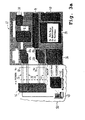
- FIG. 3 a shows an exchange 12, which has connection groups 18 a, 20 a through which a concentrator interface 10 is controlled.
- a second concentrator interface 44 is activated.
- the terminal groups 18a, 18b, 20a, 20b are connected to the message distribution system 14 of the central office 12.
- the messaging system 14 of the central office 12 is further connected to the switching center 16 of the central office, a communications processor 34 and a protocol terminator 40, e.g. may be a protocol termination means of the signaling system no. 7.
- the message distribution system 14 is further connected to a packet control unit 36.
- the concentrator interface 10 includes eight PCM30 links. Four of the eight PCM30 links each are connected to the connection groups 18a, 20a, of which only two PCM30 links are shown in FIG. 3a.
- the concentrator interface 44 also includes eight PCM links. Of these eight PCM links, four PCM30 links 30, 32 are connected to the terminal groups 18b, 20b, of which only two are also shown.
- the PCM30 links 26, 28 are routed to a media gateway 46.
- the PCM30 links 30, 32 are also routed to the media gateway 46.
- the media gateway 46 provides an interface between the circuit-switched communications network and a packet-switched communications network 50.
- a subscriber 48 is a subscriber to the packet-switched communications network 50.
- the packet-switched communications network 50 is an IP network.
- the subscriber 48 is set up at the concentrator interface 10.
- the coordination processor 34 and other central units of the exchange 12 provide the concentrator interfaces 10, 44, in particular memory areas in the database of the switching center 12, computing capacity and signaling capacity for subscriber signaling, for subscriber administration and for service and maintenance of the concentrator interface 10, 44 and the subscriber lines ready, which are connected via these interfaces 10, 44.
- the user data is supplied from the terminal of the subscriber 48 with the aid of the IP network 50 to the media gateway 46.
- the user 48 transmits the user data as data packets to the media gateway 46.
- the media gateway 46 converts these data packets into data of the circuit-switching communication network of the switching center 12 and transmits them by means of the PCM30 links 26, 28 to the port groups 18a, 20a. These payloads are transmitted by the port groups 18a, 20a by means of unillustrated connections between the port groups 18a, 20a and the switching network 16.
- the switching network 16 switches the connection to the further subscriber, which is set up at the concentrator interface 44.
- the user data of the subscriber 48 are transmitted from the switching network 16 to one of the terminal groups 18b, 20b.
- the PCM30 links 30, 32 these data are transmitted from the port groups 18b, 20b via the concentrator interface 44 to the media gateway 46, which converts these data into data packets which are supplied to the further subscriber with the aid of the IP network 50.
- the transmission of the user data of the other participant in the direction of participants 48 is carried out in the same way vice versa.
- the further subscriber can also be a subscriber of the circuit-switching communication network, which can be reached, for example, via a further connection group 38 of the exchange 12. If the subscriber is a subscriber to a further exchange of the circuit-switching communication network, the data is transmitted between the further exchange and the exchange 12 by means of the circuit-switched communication network.
- the further subscriber can also be another subscriber of the packet-switching communications network, which is connected via the media gateway 46 or another media gateway to the switching center 12 or to another switching center.
- the subscriber signaling signaling data is not transmitted from the port groups 18a, 18b, 20a, 20b to time slots of the PCM links or communication channels routed in the PCM links to the port groups 18a, 18b, 20a, 20b this is known when connecting concentrator interfaces 10, 44 with conventional subscribers.
- the signaling information for subscriber signaling is exchanged via the message distribution system 14 between the port groups 18a, 18b, 20a, 20b and the packet control unit 36.
- the packet control unit 36 takes over the coordination of the control of the media gateway 46 and the implementation of the subscriber signaling of the subscriber 48 to the used in the IP network 50 by the subscriber 48 signaling method H.323.
- the connection between the packet control unit 36 and the media gateway 46 for controlling the media gateway 46 is represented by a dotted line.
- the subscriber signaling of the subscriber 48 takes place via a gatekeeper 42, which is connected to the packet control unit 36.
- the connection between the packet control unit 36 and the gatekeeper 42 is represented by two dashed lines, the subscriber signaling between the packet control unit 36 and the gatekeeper 42 and between the gatekeeper 42 and the subscriber 48 using the H.225 / H.245 standard.
- the gatekeeper 42 provides an access control function and a firewall function.
- FIG. 3b shows a second exchange 22 similar to the exchange 12 shown in FIG. 3a.
- the exchange 22 does not have a switching network for switching payload connections with respect to the switching center 12 of FIG. 3a.
- the subscriber signaling and the connection control takes place with the aid of the exchange 22 in the same manner as has already been described for the exchange 12 of FIG. 3a.
- the switch 22 has a first concentrator interface Vx 58 and a second concentrator interface Vx 60 which, unlike the concentrator interfaces 10 and 44 of FIG. 3, do not include PCM links.
- the user data is transmitted or guided exclusively via the IP network 50.
- FIG. 4 shows an arrangement in which the switching center 12 switches a voice connection between the subscriber 48 and a further subscriber 56. Both the subscriber 48 and the subscriber 56 are connected via the IP network 50.
- the media gateway 46 is connected to the central office 12 via the concentrator interface 10 by means of PCM links.
- a media gateway 54 is connected to the central office 12 via PCM links via a concentrator interface 52. Both media gateways 46, 54 are connected to the IP network 50.
- the user data for the voice connection between the subscriber 48 and the subscriber 56 are transmitted between the subscriber 48 and the media gateway 46 and between the media gateway 54 and the subscriber 56 with the aid of data packets.
- the media gateways 46, 54 convert these data packets into data of a circuit-switching communications network and transmit them via the PCM links between the media gateways 46 and 54 via the interfaces 10 and 52 to the switching center 12.
- the switching network 16 of the switching center 12 switches a connection for transmitting this user data.
- the signaling data for subscriber signaling is exchanged via the message distribution system 14 with the packet control unit 36.
- the packet control unit 36 has in each case a connection to the media gateway 46 and to the media gateway 54, which is indicated in FIG. 4 by dotted lines.
- the packet control unit 36 controls the media gateways 46, 54.
- the subscriber signaling is transmitted from the packet control unit 36 of the switching center 12 to the gatekeeper 42 in an IP-based manner. In Figure 4, this transfer is shown by means of a dashed line.
- the gatekeeper 42 transmits the subscriber signaling data of the subscriber 48 and the subscriber signaling data of the subscriber 56 by means of the IP network 50.
- the signaling information for subscriber signaling is no longer routed via the PCM links of the concentrator interfaces 10, 52.
- the subscriber signaling is rather carried out via the packet control unit 36, which controls both the media gateways 46, 54 and the subscriber signaling to the needs of the participants 48, 56 of the IP network 50, such as H.323 or SIP signaling, converts and and converts the IP-based subscriber signaling in the reverse direction to the signaling standard of the concentrator interface 10, 52 and forwards them to the respective port group.
- the subscribers 46, 48 are introduced as subscribers of a new type. These subscribers can be assigned properties of an ISDN basic access or an ISDN private branch access. However, the subscribers of the packet-switched communications network are identified in the database so that they can only be connected to concentrator interfaces 10, 44, 52, in which the subscriber signaling of the subscribers 46, 48 assigned to them takes place directly via a packet control unit 36.
- subscribers 48, 56 may be provided with main and extension line features.
- concentrator interfaces 10, 44, 52 no conventional participants of the circuit-switching communication network can be connected, as no direct, guided over the time slots of the associated PCM30 links subscriber signaling takes place via these interfaces 10, 44, 52.
- These concentrator interfaces 10, 44, 52 can thus also be referred to as virtual concentrator interfaces.
- these interfaces 10, 44, 52 are also marked, so that no conventional participants of the circuit-switching communication network can be connected to these interfaces 10, 44, 52.
- Both in the configuration of the interfaces 10, 44, 52 and in the setup and configuration of the participants 48, 56 is an administrative review, which ensures that no conventional participants can be connected to the interfaces 10, 44, 52 and that the Subscriber 48, 56 only interfaces 10, 44, 52 are assigned, which support the inventive method for connecting subscribers 48, 56 of a packet-switched communication network 50.
- the routing of the user data stream via the switching center 12 enables voice processing, in particular of tones, of announcements, dialogues and two-tone signals, which can be introduced and / or processed in a conventional manner by the switching center.
- voice processing in particular of tones, of announcements, dialogues and two-tone signals, which can be introduced and / or processed in a conventional manner by the switching center.
- events are used which arise in the switching-active terminal group of the switching center 12 and the switching through of a time slot of the concentrator interface 10, 52 associated PCM path to a subscriber channel of the subscriber 48, 50 relate.
- the beginning and end of such an assignment is transmitted from the port group 18a, 18b, 20a, 20b to the packet control unit 36 and leads here to the appropriate setting of gateway 46, 54 and terminal of the subscriber 48, 50th
- FIG. 5 shows a further arrangement for processing signaling data and for connection control of subscribers 48, 56, which are connected via the IP network 50.
- the user data between the subscriber 48 and the subscriber 56 is not routed via the exchange 12 but is transmitted directly via the IP network 50.
- the media gateways 46 and 54 are not required. It is also possible to dispense with the PCM30 links of the concentrator interface 10 at the port groups 18a, 20a and 20, since no user data is to be transmitted via the port groups 18a, 20a. The same applies to the concentrator interface 52.
- the subscriber 48 of the concentrator interface 10 and the subscriber 56 of the concentrator interface 52 are assigned in the database of the switching center 12. This is indicated by the thin-drawn connection line between the interface 10 and the subscriber 48 and between the interface 52 and the subscriber 56.
- the subscriber signaling of the subscribers 48, 56 takes place as already described in FIG.
- the packet control unit 36 of the switching center 12 also supplies the signaling data to the gatekeeper 42.
- the gatekeeper 42 has the same functionality as the gatekeeper described in the embodiment of FIG.
- the concentrator interfaces 10, 44, 52 and the subscribers 48, 56 are identified in the database of the exchange 12.
- the marking of the concentrator interface 10, 44, 52 allows the software of the terminal groups 18a, 18b, 20a, 20b to dispense with actions that are no longer useful when connecting participants 48, 56 packet-switched communication networks 50.
- the activation of the control and signaling channels of the concentrator interface 10, 44, 52 is prevented.
- the commissioning of the concentrator interfaces 10, 44, 52 associated with PCM sections 26, 28, 30, 32 are prevented, which is required in the present embodiment.
- the central parts of the exchange 12 however, the availability of no longer required functions and the enforcement of no longer required functions is signaled to avoid in particular unwanted or meaningless error responses or to keep the adjustment effort in the central parts of the exchange 12 low.
- essential attributes which are indispensable for the central office 12, but which are not relevant for these concentrator interfaces 10, 44, 52, can be automatically generated by the system on the user interface and thus do not have to be introduced via the operator interface of the central office 12 by an operator.
- control units can be servers, for example.
- the parcel control unit 36 determines the subscriber addresses of the subscriber 48 and the subscriber 56 in the IP network 50 with the aid of this control unit on the basis of the E.164 telephone number, and thus its availability for occupancy by another subscriber, ie for a B-side occupancy , In the case of an A-side occupancy, the implementation of the A-number to the responsible for the subscriber concentrator interface, whereby the A-side switching line responsible connection group is selected.
- the above server function was referred to as GK-RAS in the context of the embodiment of FIGS. 3a and 3b.
- the concentrator interface 10, 44, 52, 58, 60 may comprise SDH links.
Landscapes
- Engineering & Computer Science (AREA)
- Computer Networks & Wireless Communication (AREA)
- Data Exchanges In Wide-Area Networks (AREA)
- Mobile Radio Communication Systems (AREA)
Abstract
Description
Die Erfindung betrifft ein Verfahren zur Verarbeitung von Signalisierungsdaten und zur Verbindungssteuerung von Teilnehmern in paketvermittelnden Kommunikationsnetzen. Ein Teilnehmer ist mit einem paketvermittelnden Kommunikationsnetz verbunden. Zur Teilnehmersignalisierung werden Signalisierungsinformationen zwischen einer Vermittlungsinstanz und dem Teilnehmer übertragen. Ferner betrifft die Erfindung ein Netzelement.The invention relates to a method for processing signaling data and for connection control of subscribers in packet-switched communication networks. A subscriber is connected to a packet-switched communication network. For subscriber signaling, signaling information is transmitted between a switching entity and the subscriber. Furthermore, the invention relates to a network element.
Konventionelle Telekommunikationsnetze haben beim Stand der Technik Vermittlungsknoten, d.h. Vermittlungsstellen bzw. Vermittlungssysteme. Diese Vermittlungsknoten umfassen Anschlussgruppen, sogenannte periphere Einrichtungen, zum Anschluss von Teilnehmern oder Leitungen, eine zentrale Rechnerplattform, eine Nachrichtenverteileinrichtung und weitere zentrale Einheiten, wie z.B. ein Koppelfeld, Protokollabschlusseinrichtungen des Nr. 7 Signalisierungssystems, Hintergrundspeicher und Bedieneinrichtungen. Ein Blockschaltbild eines solchen Vermittlungsknotens ist in Figur 1 dargestellt.Conventional telecommunications networks have in the prior art switching nodes, i. Switching centers or switching systems. These switching nodes comprise access groups, so-called peripheral devices, for connecting subscribers or lines, a central computer platform, a message distribution device and further central units, such as e.g. a switch fabric, protocol termination equipment of the No. 7 signaling system, background storage and controls. A block diagram of such a switching node is shown in FIG.
Die Anschlussgruppen erfüllen wesentliche, an die Sprachkanäle der Anschlussgruppen gebundene vermittlungstechnische Aufgaben. Sie enthalten daher vermittlungstechnische, betriebstechnische und administrative Programme sowie die der Anschlussgruppe zugehörigen Dateninformationen, wie Anschlusslage, Signalisierung, Berechtigungen, Rufnummern, individuelle Charakteristika von Verbindungsleitungen und Teilnehmeranschlüssen sowie den Ausbauzustand und die Konfiguration der Anschlussgruppe.The access groups fulfill essential call-processing tasks linked to the voice channels of the access groups. They therefore contain call processing, operational and administrative programs as well as the data information associated with the connection group, such as connection status, signaling, authorizations, telephone numbers, individual characteristics of connection lines and subscriber lines as well as the configuration and configuration of the access group.
Die zentrale Rechnerplattform dient der koordinierten Steuerung des Verbindungsaufbaus und des Verbindungsabbaus sowie der Reaktion auf administrative und fehlerbedingte Konfigurationsveränderungen. Die peripheren Einrichtungen sind über das Nachrichtensystem untereinander und mit der gemeinsamen Rechnerplattform verbunden. Die weiteren zentralen Systemkomponenten stellen dem Vermittlungssystem des Vermittlungsknotens Spezialfunktionen, z.B. für die Durchschaltung von Sprachkanälen, für die Bearbeitung von Signalisierungsprotokollen, für die Realisierung von Betreiberschnittstellen oder für die Speicherung von Massendaten, zur Verfügung. Aus Gründen der Ausfallsicherheit sind die zentralen Komponenten des Vermittlungssystems redundant ausgelegt, d.h. z.B. doppelt. Wenn keine erhöhten Anforderungen an die vermittlungstechnische Verfügbarkeit der Teilnehmer und der Verbindungsleitungen des Vermittlungssystems gestellt sind, werden die Anschlussgruppen nicht redundant ausgeführt. Sollen jedoch stabile Verbindungen über den Ausfall einer Anschlussgruppe hinaus verfügbar sein, werden auch die Anschlussgruppen redundant ausgelegt.The central computer platform serves for the coordinated control of the connection setup and the disconnection as well as the reaction to administrative and error-related configuration changes. The peripheral devices are connected to each other via the message system and to the common computer platform. The other central system components provide the switching system of the switching node with special functions, e.g. for the implementation of voice channels, for the processing of signaling protocols, for the realization of operator interfaces or for the storage of mass data. For reasons of reliability, the central components of the switching system are designed redundantly, i. e.g. double. If no increased demands are placed on the switching-based availability of the subscribers and the connection lines of the switching system, the connection groups are not executed redundantly. However, if stable connections beyond the failure of a port group are to be available, the port groups will also be designed redundantly.
Konventionelle Teilnehmer eines Vermittlungssystems sind direkt und physikalisch an die Anschlussgruppen angeschlossen, oder sie sind physikalisch an einem den Anschlussgruppen vorgelagerten Teilnehmerkonzentrator angeschlossen, der mit Hilfe genormter Konzentratorschnittstellen, wie z.B. einer Schnittstelle der V5.X-Schnittstellenreihe oder einer TR303-Schnittstelle, oder herstellerspezifischen Konzentratorschnittstellen, wie z.B. einer V93-Schnittstelle oder einer V95-Schnittstelle, an die Vermittlungsstelle angeschlossen ist. Für sprachkanalbezogene Verbindungen werden Signalisierungsdaten zur Teilnehmersignalisierung und Nutzdaten über die Vermittlungsstelle geführt. Die Nutzdaten werden hierbei mit einer Datenübertragungsrate von 64 kbit/s oder mit einem Vielfachen dieser Datenübertragungsrate durchgeschaltet. Die Signalisierungsdaten zur Teilnehmersignalisierung werden für Teilnehmergruppen, d.h. für mehrere Teilnehmer gemeinsam, mit Hilfe eines Kommunikationskanals gemäß der Definition der benutzten Konzentratorschnittstelle zwischen Teilnehmerkonzentrator auf der einen Seite und der Vermittlungsstelle auf der anderen Seite bidirektional übertragen. Neben der Signalisierung können im Signalisierungsweg zusätzlich end-to-end Paketdaten (user-to-user Signalling) oder Paketdaten zur Weiterreichung an ein Packet-Handler-Interface geführt werden.Conventional participants of a switching system are directly and physically connected to the terminal groups, or they are physically connected to a subscriber concentrator upstream of the terminal groups, using standardized concentrator interfaces, such as an interface of the V5.X interface series or a TR303 interface, or manufacturer-specific concentrator interfaces , such as a V93 interface or a V95 interface, is connected to the central office. For voice channel-related connections signaling data for subscriber signaling and payload data are routed through the exchange. The payload data is switched through here with a data transfer rate of 64 kbit / s or at a multiple of this data transfer rate. The signaling data for subscriber signaling are common to subscriber groups, ie for several subscribers Assistance of a communication channel according to the definition of the used concentrator interface between subscriber concentrator on the one hand and the switch on the other hand bidirectional transfer. In addition to signaling, in the signaling path additional end-to-end packet data (user-to-user signaling) or packet data can be passed on to a packet handler interface for forwarding.
Bei einer Verbindung zwischen Teilnehmern eines Paketnetzes (z.B. Voice Over Packet) werden die Nutzdaten üblicherweise nicht an eine Vermittlungsstelle herangeführt. Das Heranführen der Nutzdaten an eine Vermittlungsstelle ist nur dann erforderlich, wenn ein an der Verbindung beteiligter Teilnehmer an ein konventionelles leitungsvermittelndes Kommunikationsnetz, z.B. ein Kommunikationsnetz mit Zeitmultiplextechnik, angeschlossen ist und somit nicht direkt über das Paketnetz erreichbar ist - siehe
Die Teilnehmer im Paketnetz sind bezüglich ihrer Signalisierung nicht hardwaremäßig einem Teilnehmerkonzentrator oder einer Konzentratorschnittstelle einer Vermittlungsstelle des leitungsvermittelnden Kommunikationsnetzes zugeordnet. Die Teilnehmer haben weder Leitungen zur analogen Signalisierung noch einen D-Kanal zur Signalisierung, der an einen festen, einer Vermittlungsstelle vorgelagerten Teilnehmerkonzentrator herangeführt ist. Die Signalisierung bei Verbindungen zwischen Teilnehmern eines paketvermittelnden Kommunikationsnetzes kann auch für Sprachverbindungen zwischen diesen Teilnehmern beim Stand der Technik nicht mit Hilfe einer konventionellen Vermittlungsstelle des leitungsvermittelnden Kommunikationsnetzes durchgeführt werden. Werden Verbindungswünsche von Telephonieteilnehmern eines Paketnetzes mit Hilfe einer Vermittlungsstelle oder eines Servers, der Vermittlungsfunktionen bereitstellt, bearbeitet, so erfolgt die Signalisierung mit Mitteln des Paketnetzes, d.h. die Signalisierungsdaten werden paketorientiert transportiert.The subscribers in the packet network are not in terms of their hardware a subscriber concentrator or associated with a concentrator interface of an exchange of the circuit-switching communication network. The subscribers have neither lines for analog signaling nor a D channel for signaling, which is brought to a fixed, an exchange upstream subscriber concentrator. The signaling in connections between subscribers of a packet-switched communication network can not be carried out for voice connections between these subscribers in the prior art with the help of a conventional switching center of the circuit-switched communication network. If connection requests from telephone subscribers of a packet network are processed by means of an exchange or a server providing switching functions, the signaling takes place by means of the packet network, ie the signaling data are transported in a packet-oriented manner.
Telephonieteilnehmer in einem paketvermittelnden Kommunikationsnetz sind z.B. Teilnehmer, die mit einem auf einem Internet-Protokoll basierenden Netz direkt oder über eine Wählverbindung verbunden sind. Neben einem Internetzugriff werden dem Teilnehmer auch Sprach- und/oder Faxdienste zur Verfügung gestellt. Diese Sprach- und/oder Faxdienste sollen den gleichen Leistungsumfang haben, wie ihn konventionelle Telefone und Faxgeräte bieten. Die Nutzdaten eines solchen Teilnehmers werden gemäß Internet-Protokoll als Datenpakete übertragen, z.B. gemäß dem sogenannten Transmission Control Protocol / User Datagramm Protocol (TCP/UDP). Die Übertragung von Signalisierungsinformationen erfolgt im paketvermittelnden Kommunikationsnetz mit Hilfe von Signalisierungspaketen gemäß definierten Standards, wie z.B. H.323, H.225, H.245, H.450 und SIP.Telephone subscribers in a packet-switched communications network are e.g. Subscribers connected to a network based on an Internet Protocol directly or via a dial-up connection. In addition to Internet access, the subscriber will also be provided with voice and / or fax services. These voice and / or fax services should have the same scope of services that conventional telephones and fax machines offer. The payload of such a subscriber is transmitted as data packets according to the Internet Protocol, e.g. according to the so-called Transmission Control Protocol / User Datagram Protocol (TCP / UDP). The transmission of signaling information takes place in the packet-switched communication network by means of signaling packets according to defined standards, such as e.g. H.323, H.225, H.245, H.450 and SIP.
In paketvermittelnden Kommunikationsnetzen erfolgt die Übertragung von Signalisierungsdaten und die Übertragung von Nutzdaten auf getrennten Übertragungswegen. Die Nutzdaten werden dem weiteren Teilnehmer direkt zugeführt. Ist eine Wandlung des Nutzdatenformats notwendig, so werden die Nutzdaten einer Schnittstelleneinheit zur Wandlung zugeführt, z.B. einem Mediagateway (MG). Die Signalisierungsdaten werden mit Hilfe von Signalisierungsdatenpaketen einer Vermittlungsinstanz zugeführt, welche die Verbindungssteuerung durchführt.In packet-switched communication networks, the transmission of signaling data and the transmission of user data take place on separate transmission paths. The user data is fed directly to the other subscriber. Is a Conversion of the user data format necessary, the user data of an interface unit for conversion are supplied, for example, a media gateway (MG). The signaling data are supplied by means of signaling data packets to a switching entity which performs the connection control.
Die International Telecommunication Union (ITU) hat mit ihrem Gremium ITU-T den H.323-Standard für Datenübertragung in IP-basierten Kommunikationsnetzen definiert. Gemäß dem H.323-Standard sind Komponenten, wie z.B. Terminals, Gateways, Gatekeeper und Multipoint Control Units vorgesehen und definiert, die an einer solchen Verbindung beteiligt sind. Ein H.323-Terminal entspricht dem Teilnehmer des paketvermittelnden Kommunikationsnetzes. Gateways kommen dann zum Einsatz, wenn die Verbindung z.B. über ein öffentliches Telefonnetz geführt werden muss oder ein Gesprächspartner ein an eine Vermittlungsstelle des öffentlichen Telefonnetzes angeschlossener Teilnehmer ist. Multipoint Control Units sind vorgesehen, um z.B. Konferenzschaltungen aufzubauen.The International Telecommunication Union (ITU), with its ITU-T body, has defined the H.323 standard for data transmission in IP-based communication networks. According to the H.323 standard, components such as e.g. Terminals, gateways, gatekeepers and multipoint control units are involved and defined, which are involved in such a connection. An H.323 terminal corresponds to the subscriber of the packet-switched communication network. Gateways are used when the connection is e.g. must be conducted via a public telephone network or a call partner is a subscriber connected to an exchange of the public telephone network. Multipoint Control Units are provided for e.g. Building conference circuits.
Als zentrale Komponente ist der Gatekeeper am Verbindungsaufbau beteiligt. Dieser kann als Vermittlungsstelle im paketvermittelnden Kommunikationsnetz angesehen werden. Der Gatekeeper stellt seiner Zone Funktionen bereit, die unter anderem zur Zugangskontrolle, zur Signalisierung, zur Verbindungssteuerung und zur Vergebührung dienen. Mit Hilfe des Gatekeepers erfolgt auch die für den Zugang zum öffentlichen Telefonnetz notwendige Rufnummernzuordnung (E.164) zu der für den Teilnehmer des paketvermittelnden Kommunikationsnetzes gültigen Teilnehmeradresse. In einem auf dem Internet-Protokoll basierenden Kommunikationsnetz, in einem sogenannten IP-Netz, ist die Adresse des Teilnehmers die IP-Adresse. Der Gatekeeper ist somit keine Vermittlungsstelle eines öffentlichen Telekommunikationsnetzes, sondern eine Steuereinheit im IP-basierten Kommunikationsnetz. Eine solche Steuereinheit ist z.B. ein Server.As a central component of the gatekeeper involved in establishing a connection. This can be regarded as an exchange in the packet-switched communication network. The gatekeeper provides functions for its zone, including access control, signaling, connection control and charging. With the help of the gatekeeper also necessary for access to the public telephone network number assignment (E.164) to the valid for the subscriber of the packet-switching communication network participant address takes place. In a communication protocol based on the Internet Protocol, in a so-called IP network, the address of the subscriber is the IP address. The gatekeeper is thus not an exchange of a public telecommunications network, but a control unit in the IP-based communication network. Such a control unit is eg a server.
Wollen Netzbetreiber leitungsvermittelnder Kommunikationsnetze auch Teilnehmern paketvermittelnder Kommunikationsnetze Kommunikationsdienstleistungen anbieten, um so neue Kunden hinzuzugewinnen, müssen diese Netzbetreiber neuartige technische Ausrüstung hinzukaufen. Diese neuartige technische Ausrüstung hat gegenüber konventionellen Vermittlungsstellen andere Eigenschaften, z.B. in Bezug auf das Ausfallverhalten und die Performance, andere Standards der Bedienung und Vergebührung sowie andere Hersteller. Dadurch entstehen dem Netzbetreiber nicht nur erhebliche Anschaffungskosten, sondern auch zusätzliche Betriebskosten, z.B. für Unterweisungen des Bedienpersonals. Eine hohe Verfügbarkeit der neuartigen technischen Ausrüstung und das Implementieren von Dienst- und Leistungsmerkmalen sowie bekannter Vergebührungsstandards ist, wenn überhaupt, nur mit erheblichem finanziellen Aufwand möglich.If network operators of circuit-switched communications networks also want to offer communication services to subscribers of packet-switched communications networks in order to gain new customers, these network operators must purchase new types of technical equipment. This novel technical equipment has different characteristics than conventional exchanges, e.g. in terms of failure behavior and performance, other operating and billing standards and other manufacturers. As a result, the network operator incurs not only significant initial costs, but also additional operating costs, e.g. for instructions of the operating personnel. High availability of the novel technical equipment and implementation of service and performance features as well as known charging standards is possible, if at all, only with considerable financial outlay.
Soll eine konventionelle Vermittlungsstelle eines leitungsvermittelnden Kommunikationsnetzes die Verbindungssteuerung bzw. die Verarbeitung von Signalisierungsdaten für Teilnehmer eines paketvermittelnden Kommunikationsnetzes durchführen, so müssen die zur Teilnehmersignalisierung relevanten paketnetzspezifischen Signalisierungsverfahren in der Vermittlungsstelle implementiert werden. Weiterhin muss in der Vermittlungsstelle ein Signalisierungszugriff zum paketvermittelnden Kommunikationsnetz implementiert werden, sowie der softwaremäßige Zugriff auf die Teilnehmer des paketvermittelnden Kommunikationsnetzes sichergestellt sein. Diese völlig neuartigen Anforderungen an eine konventionelle Vermittlungsstelle erfordern eine aufwendige Anpassung und Umstrukturierung von Hardwarekomponenten und Softwarekomponenten. Für diese Änderungen und Umstrukturierungen ist ein erheblicher Entwicklungsaufwand notwendig.If a conventional switching center of a circuit-switching communication network is to carry out the connection control or the processing of signaling data for subscribers of a packet-switched communications network, the packet-network-specific signaling methods relevant for subscriber signaling must be implemented in the exchange. Furthermore, a signaling access to the packet-switching communication network must be implemented in the exchange, and the software-based access to the subscribers of the packet-switching communication network must be ensured. These completely new requirements for a conventional exchange require a complex adaptation and restructuring of hardware components and software components. Significant development effort is required for these changes and restructuring.
Aufgabe der Erfindung ist es, ein Verfahren und eine Anordnung anzugeben, das bzw. die auf einfache Weise ein Netzelement eines leitungsvermittelnden Kommunikationsnetzes zur Teilnehmersignalisierung von Teilnehmern eines paketvermittelnden Kommunikationsnetzes nutzt.The object of the invention is to provide a method and an arrangement, which or simply a network element a circuit-switching communication network for subscriber signaling of subscribers of a packet-switched communication network uses.
Diese Aufgabe wird für ein Verfahren durch die Merkmale des Patentanspruchs 1 gelöst. Für eine Anordnung wird die Aufgabe durch die Merkmale des Patentanspruchs 25 gelöst. Vorteilhafte Weiterbildungen sind in den abhängigen Ansprüchen angegeben.This object is achieved for a method by the features of
Bei dem Verfahren mit den Merkmalen des Patentanspruchs 1 wird eine konventionelle Konzentratorschnittstelle in dem Netzelement, das z.B. eine Vermittlungsstelle eines leitungsvermittelnden Kommunikationsnetzes ist, installiert. Durch ein solches Verfahren wird erreicht, dass der Aufwand zur Änderung der Software des Netzelementes gering ist und wenig interne Schnittstellen der Vermittlungsstelle von den Änderungen betroffen sind. Konventionelle Vermittlungsstellen, die als Netzelement in leitungsvermittelnden Kommunikationsnetzen genutzt werden, haben im allgemeinen, z.B. durch Redundanz, eine hohe Verfügbarkeit, wodurch Störungen und Ausfälle von Teilnehmeranschlüssen selten auftreten. Durch das Nutzen einer solchen Vermittlungsstelle zur Verarbeitung von Signalisierungsdaten und zur Verbindungssteuerung von Teilnehmern eines paketvermittelnden Kommunikationsnetzes haben auch diese Teilnehmer eine hohe Verfügbarkeit von Kommunikationsdiensten.In the method having the features of
Durch das erfindungsgemäße Verfahren ist es weiterhin einfach möglich, Signalisierungsdaten zwischen einem Teilnehmer eines paketvermittelnden Kommunikationsnetzes und einer Vermittlungsstelle eines leitungsvermittelnden Kommunikationsnetzes auszutauschen. Die Übertragung der Nutzdaten kann somit durch die Vermittlungsstelle gesteuert werden. Eine Vergebührung gemäß den in Telekommunikationsnetzen üblichen Anforderungen ist einfach durchführbar. Mit Hilfe des Verfahrens kann die Steuerung sowohl für Verbindungen erfolgen, bei denen die Nutzdaten über die Vermittlungsstelle geführt werden, als auch für Verbindungen, bei denen die Nutzdaten direkt zwischen den Teilnehmern, z.B. mit Hilfe des paketvermittelnden Kommunikationsnetzes, übertragen werden.The method according to the invention furthermore makes it possible to exchange signaling data between a subscriber of a packet-switched communications network and an exchange of a circuit-switched communications network. The transmission of the user data can thus be controlled by the exchange. Billing according to the requirements customary in telecommunication networks is easy to carry out. With the aid of the method, the control can take place both for connections in which the User data are routed through the exchange, as well as for connections in which the user data directly between the participants, eg using the packet-switched communication network, are transmitted.
Der Teilnehmer des paketvermittelnden Kommunikationsnetzes ist auch für Teilnehmer von leitungsvermittelnden Kommunikationsnetzen eindeutig adressierbar. Mit Hilfe des erfindungsgemäßen Verfahrens können gleichzeitig auch mehrere Verbindungen zu einem Teilnehmer des paketvermittelnden Kommunikationsnetzes aufgebaut werden. Mit Hilfe der erfindungsgemäßen Vermittlungsstelle kann der Teilnehmer des paketvermittelnden Kommunikationsnetzes mit weiteren Teilnehmern des paketvermittelnden Kommunikationsnetzes und/oder mit Teilnehmern des leitungsvermittelnden Kommunikationsnetzes eine Gruppe bilden. Den Teilnehmern der Gruppe stehen innerhalb der Gruppe weitere Dienst- und/oder Leistungsmerkmale zur Verfügung. Eine solche Gruppe kann z.B. eine CENTREX-Gruppe sein, die auch als CENTREX-Business-Group bezeichnet wird.The subscriber of the packet-switching communication network is also uniquely addressable for subscribers of circuit-switched communication networks. With the aid of the method according to the invention, several connections to a subscriber of the packet-switching communications network can be set up at the same time. With the help of the exchange according to the invention, the subscriber of the packet-switching communication network can form a group with other subscribers of the packet-switching communications network and / or with subscribers of the circuit-switching communications network. Members of the group have access to additional services and / or features within the group. Such a group may e.g. a CENTREX group, also known as the CENTREX Business Group.
Die Verarbeitung von Signalisierungsdaten und die Verbindungssteuerung des Teilnehmers des paketvermittelnden Kommunikationsnetzes kann auf der Grundlage der für einen Basisanschluss eines leitungsvermittelnden Kommunikationsnetzes oder der für einen primären Multiplexanschluss eines leitungsvermittelnden Kommunikationsnetzes bekannten Leistungsmerkmale erfolgen. Somit ist auch eine nebenstellenartige Behandlung der Teilnehmer des paketvermittelnden Kommunikationsnetzes möglich. Die Vermittlungsstelle kann dem Teilnehmer des paketvermittelnden Kommunikationsnetzes damit Dienst- und/oder Leistungsmerkmale zur Verfügung stellen, die in leitungsvermittelnden Kommunikationsnetzen möglich sind.The processing of signaling data and the connection control of the subscriber of the packet-switched communication network can be carried out on the basis of the features known for a base connection of a circuit-switching communication network or of a primary multiplex connection of a circuit-switching communication network. Thus, an extension-like treatment of the participants of the packet-switching communication network is possible. The exchange can thus provide the subscriber of the packet-switching communications network with service and / or performance features that are possible in circuit-switching communications networks.
Mit dem Installieren und Einrichten einer Konzentratorschnittstelle in einer Vermittlungsstelle werden Datenspeicher mit Teilnehmerbezug in den zentralen Einheiten der Vermittlungsstelle sowie in peripheren Einheiten der Vermittlungsstelle, wie z.B. in den Anschlussgruppen, verfügbar. In diesen Datenspeichern sind Eigenschaften der Teilnehmer gespeichert, die der Konzentratorschnittstelle zugeordnet sind. Solche Eigenschaften sind z.B. Rufnummer, Typ des Anschlusses, Verfügbarkeit von Leitungsmerkmalen, Sperrinformationen, Gruppenzugehörigkeit zu CENTREX usw. Weiterhin werden für die der Konzentratorschnittstelle zugeordneten Teilnehmer vermittlungstechnische Ressourcen, wie z.B. Prozessorkapazität, Signalisierungsterminierungskapazität und Nachrichtenverteilkapazität bereitgestellt.With the installation and establishment of a concentrator interface in an exchange, data stores with subscriber reference are located in the central units of the exchange as well as in peripheral units of the exchange, as in the connection groups, available. In these data stores properties of the participants are stored, which are assigned to the concentrator interface. Such features include telephone number, type of connection, availability of line characteristics, blocking information, group membership to CENTREX, etc. Furthermore, switching-center resources such as processor capacity, signaling termination capacity and message distribution capacity are provided for the subscribers associated with the concentrator interface.
Die in den peripheren Einheiten der Vermittlungsstelle erzeugten Signalisierungsdaten zur Teilnehmersignalisierung der Teilnehmer des paketvermittelnden Kommunikationsnetzes werden einer Paketsteuereinheit zugeführt, die z.B. direkt mit dem paketvermittelnden Kommunikationsnetz verbunden ist und die Signalisierungsdaten zur Teilnehmersignalisierung der Teilnehmer des paketvermittelnden Kommunikationsnetzes in Signalisierungspakete des paketvermittelnden Kommunikationsnetzes konvertiert. Die Administration und Zustandsänderungen, z.B. bei Ausfall und Wiederverfügbarkeit, der Konzentratorschnittstelle für Teilnehmer des paketvermittelnden Kommunikationsnetzes erfolgen auf gleiche Art und Weise wie bei Konzentratorschnittstellen, an die Teilnehmer des leitungsvermittelnden Kommunikationsnetzes angeschlossen sind. Durch die Verarbeitung von Signalisierungsdaten und die Verbindungssteuerung mit Hilfe einer konventionellen Vermittlungsstele ist ein Gatekeeper mit Vermittlungsfunktion nicht erforderlich. Die Funktion der Speicherung der aktuellen Erreichbarkeit eines paketbasierten Teilnehmers im Paketnetz und die Zuordnung seiner vermittlungstechnischen Adresse, d.h. seiner E.164-Rufnummer, zu seiner unter Umständen temporären Adresse im Paketnetz können von der Vermittlungsstelle vorgelagerten Servern durchgeführt werden. Diese Server übernehmen zugleich die Funktion der Zugangskontrolle (GK-RAS) und die Funktion eines Firewalls zum Paketnetz hin.The signaling data for subscriber signaling of the subscribers of the packet-switching communication network generated in the peripheral units of the exchange are fed to a packet control unit which, for example, is connected directly to the packet-switched communications network and converts the signaling data for subscriber signaling of the subscribers of the packet-switched communications network into signaling packets of the packet-switched communications network. The administration and status changes, eg in case of failure and re-availability, of the concentrator interface for subscribers of the packet-switched communications network are carried out in the same way as in concentrator interfaces to which subscribers of the circuit-switching communications network are connected. By processing signaling data and connection control using a conventional switching office, a gatekeeper with switching function is not required. The function of storing the current accessibility of a packet-based subscriber in the packet network and the assignment of his call processing address, ie his E.164 phone number, to his possibly temporary address in the packet network can be performed by servers upstream of the exchange. At the same time, these servers assume the function of access control (GK-RAS) and the function of a firewall to the packet network.
Durch das erfindungsgemäße Verfahren können Hersteller von Vermittlungsstellen für leitungsvermittelnde Kommunikationsnetze mit geringem Entwicklungsaufwand auch eine Lösung zur Verarbeitung von Signalisierungsdaten und zur Verbindungssteuerung von Teilnehmern paketvermittelnder Kommunikationsnetze anbieten. Mit Hilfe einer solchen erfindungsgemäßen Vermittlungsstelle kann bei einer Verbindung der Vermittlungsstelle zu einem leitungsvermittelnden und zu einem paketvermittelnden Kommunikationsnetz sowohl die Verbindungssteuerung von Teilnehmern des leitungsvermittelnden Kommunikationsnetzes als auch von Teilnehmern des paketvermittelnden Kommunikationsnetzes durchgeführt werden.With the method according to the invention, manufacturers of exchanges for circuit-switching communication networks with little development effort can also offer a solution for processing signaling data and for controlling the connection of subscribers of packet-switching communication networks. With the aid of such a switching center according to the invention, both the connection control of subscribers of the circuit-switching communication network and of subscribers of the packet-switching communication network can be carried out in a connection between the exchange to a circuit-switching and a packet-switched communication network.
Bereits vorhandene leitungsvermittelnde Vermittlungsstellen des Herstellers können mit Hilfe des erfindungsgemäßen Verfahrens auch oder ausschließlich zur Verbindungssteuerung von Teilnehmern paketvermittelnder Kommunikationsnetze genutzt werden, d.h. die beim Netzbetreiber vorhandenen Vermittlungsstellen können durch den Hersteller beim Netzbetreiber entsprechend aufgerüstet werden. Investitionen für neue technische Ausrüstungen und für Schulungen des Bedien- und Wartungspersonals sind gering. Der Netzbetreiber muss bei einer Änderung der Teilnehmersignalisierung, z.B. bei der Einführung neuer Dienst- oder Leistungsmerkmale, nur ein Vermittlungssystem anpassen. Konventionelle Netzbetreiber können somit paketbasierten Teilnehmern in einem stark expandieren Marktsegment ohne großen Investitionsaufwand Kommunikationsdienstleistungen öffentlicher leitungsvermittelnder Kommunikationsnetze zur Verfügung stellen. Die Zuverlässigkeit, die Vergebührung, die Teilnehmeradministration sowie die Wartung und der Service der Vermittlungsstelle sind auch bei einem Einschluss von Teilnehmern paketvermittelnder Kommunikationsnetze wie bei einer konventionellen Vermittlungsstelle gegeben bzw. möglich. Sind zwei paketbasierte Teilnehmer an einer Verbindung beteiligt, so kann ihr Nutzdatenstrom ohne Medienkonversion im Paketnetz geführt werden, wodurch sich keine Verschlechterung der Sprachqualität ergibt.Already existing circuit-switching centers of the manufacturer can be used with the aid of the method according to the invention or exclusively for connection control of subscribers of packet-switched communication networks, ie existing at the operator network exchanges can be upgraded accordingly by the manufacturer at the network operator. Investments in new technical equipment and training for operators and maintenance staff are low. The network operator must adapt to a change in the subscriber signaling, for example, when introducing new service features, only one switching system. Conventional network operators can thus provide packet-based subscribers in a rapidly expanding market segment with communication services for public circuit-switched communications networks without major investment expenditure. Reliability, billing, subscriber administration, as well as the maintenance and service of the switch are also possible or possible with the inclusion of subscribers of packet-switched communication networks as in a conventional exchange. If two packet-based subscribers are involved in a connection, their user data stream can be routed without media conversion in the packet network, resulting in no deterioration of the voice quality.
Weitere Merkmale und Vorteile der Erfindung ergeben sich aus der folgenden Beschreibung, welche in Verbindung mit den beigefügten Zeichnungen die Erfindung an Hand von Ausführungsbeispielen erläutert. Darin zeigen:
Figur 1- eine typische Architektur eines bekannten Vermittlungssystems mit nicht-redundanten Anschlussgruppen,
Figur 2- eine Konzentratorschnittstelle des Typs V5.2, die an eine bekannte Vermittlungsstelle angeschlossen ist,
- Figur 3a
- eine Vermittlungsstelle zum Durchführen des erfindungsgemäßen Verfahrens,
- Figur 3b
- eine zweite Vermittlungsstelle zum Durchführen des erfindungsgemäßen Verfahrens,
Figur 4- zwei Teilnehmer eines paketvermittelnden Kommunikationsnetzes, deren Signalisierungsdaten mit Hilfe des erfindungsgemäßen Verfahrens verarbeitet werden, wobei die Nutzdaten über die Vermittlungsstelle geführt sind, die die Signalisierungsdaten verarbeitet, und
- Figur 5
- zwei Teilnehmer eines paketvermittelnden Kommunikationsnetzes, deren Signalisierungsdaten mit Hilfe des erfindungsgemäßen Verfahrens verarbeitet werden, wobei die Nutzdaten nicht über die Vermittlungsstelle geführt werden, die die Signalisierungsdaten verarbeitet.
- FIG. 1
- a typical architecture of a known switching system with non-redundant terminal groups,
- FIG. 2
- a concentrator interface of type V5.2 connected to a known exchange;
- FIG. 3a
- an exchange for carrying out the method according to the invention,
- FIG. 3b
- a second exchange for carrying out the method according to the invention,
- FIG. 4
- two subscribers of a packet-switching communications network whose signaling data are processed by means of the method according to the invention, wherein the user data are routed via the switching center which processes the signaling data, and
- FIG. 5
- two subscribers of a packet-switching communications network whose signaling data are processed by means of the method according to the invention, wherein the user data is not routed via the switching center which processes the signaling data.
In Figur 1 ist eine typische Struktur eines herkömmlichen Vermittlungssystems mit Hilfe eines Blockschaltbilds dargestellt. Ein solches Vermittlungssystem hat ein Koppelnetz SN (Switching Network), einen Nachrichtenverteiler MB (Message Buffer), einen Koordinationsprozessor CP (Coordination Processor), Bedieneinrichtungen NC, Hintergrundspeicher MD und Protokollabschlusseinrichtungen CCNC (z.B. gemäß Zeichengabesystem Nr. 7). Diese Elemente des Vermittlungssystems sind zur Erhöhung der Ausfallsicherheit redundant, d.h. z.B. doppelt, ausgeführt. Das Vermittlungssystem hat weiterhin Anschlussgruppen LTG (Line/Trunk Group), die mit dem Koppelnetz SN und dem Nachrichtenverteilsystem MB verbunden sind. Die Anschlussgruppen LTG werden auch als periphere Einheiten des Vermittlungssystems bezeichnet und dienen zum Anschluss von Teilnehmern und Verbindungsleitungen sowie zum Anschluss von Konzentratorschnittstellen, mit deren Hilfe z.B. separat angeordnete Anschlusseinheiten angeschlossen werden können. Wenn keine erhöhten Anforderungen an die vermittlungstechnische Verfügbarkeit der Teilnehmer und Verbindungsleitungen des Vermittlungssystems gestellt sind, werden die Anschlussgruppen LTG nicht redundant ausgeführt.FIG. 1 shows a typical structure of a conventional switching system by means of a block diagram. Such a switching system has a switching network SN (Switching Network), a message distributor MB (Message Buffer), a coordination processor CP (Coordination Processor), controls NC, background memory MD and protocol termination CCNC (eg according to signaling system no. 7). These elements of the switching system are to increase the reliability redundant, ie, for example, double executed. The switching system also has connection groups LTG (Line / Trunk Group), which are connected to the switching network SN and the message distribution system MB. The connection groups LTG are also referred to as peripheral units of the switching system and serve to connect subscribers and connection lines and to connect concentrator interfaces, with the aid of which, for example, separately arranged connection units can be connected. If no increased demands are placed on the switching-based availability of the subscribers and connection lines of the switching system, the connection groups LTG are not executed redundantly.
In Figur 2 sind eine Konzentratorschnittstelle 10 und eine Vermittlungsstelle 12 sowie Baueinheiten der Vermittlungsstelle dargestellt. Die Vermittlungsstelle 12 hat ein Nachrichtenverteilsystem 14, ein Koppelnetz 16 und Anschlussgruppen 18, 20. Die Konzentratorschnittstelle 10 hat einen Anschlussbereich 24, der mit Hilfe von acht PCM-Strecken 26a bis 26d, 28a bis 28d mit den Anschlussgruppen 18, 20 verbunden ist. Ein über die Konzentratorschnittstelle 10 angeschlossener Teilnehmeranschlusskonzentrator wird auch als Access Network (AN) bezeichnet. Mit Hilfe der PCM-Strecken 26a bis 26d, 28a bis 28d werden sowohl Nutzdaten als auch Signalisierungs- und Steuerdaten zwischen den Anschlussgruppen 18, 20 und dem Teilnehmeranschlusskonzentrator übertragen. Die der Teilnehmersignalisierung und der Übertragung von Steuerinformationen und Meldungen dienenden Daten werden mit Hilfe von Kanälen der Konzentratorschnittstelle 10 übertragen.FIG. 2 shows a
Die Signalisierungs- und Steuerkanäle haben z.B. eine Datenübertragungskapazität von 64 kbit/s und werden in den PCM-Strecken 26a bis 26d, 28a bis 28d zwischen den Anschlussgruppen 18, 20 und dem Teilnehmeranschlusskonzentrator geführt. Ist ein großes Signalisierungs- und Steuerdatenaufkommen bei der Konzentratorschnittstelle 10 zu erwarten, kann die Konzentratorschnittstelle 10 eine Vielzahl von Signalisierungs- und Steuerkanälen umfassen.The signaling and control channels have e.g. a data transfer capacity of 64 kbit / s and are routed in the PCM links 26a to 26d, 28a to 28d between the
Im Rahmen des Einrichtens, der Konfiguration und der Inbetriebnahme der Konzentratorschnittstelle 10 in der Vermittlungsstelle 12 werden für die Konzentratorschnittstelle 10 Datenspeicher mit Teilnehmerbezug in den zentralen Baueinheiten der Vermittlungsstelle 12 und in den Anschlussgruppen 18, 20 bereitgestellt. In diesen Datenspeichern werden die Eigenschaften der über diese Konzentratorschnittstelle 10 angeschlossenen Teilnehmer gespeichert. Weiterhin werden durch Einrichten, Konfiguration und Inbetriebnahme der Konzentratorschnittstelle 10 vermittlungstechnische Ressourcen, wie z.B. Prozessorkapazität, Signalisierungsterminierungskapazität, Nachrichtentransferkapazität für die über die Konzentratorschnittstelle 10 angeschlossenen Teilnehmer bereitgestellt.As part of setting up, configuring and commissioning the
Die über die Konzentratorschnittstelle 10 anschließbaren Teilnehmer können Teilnehmer mit einem ISDN-Basisanschluss, einem ISDN-Primärmultiplexanschluss oder einem analogen Teilnehmeranschluss sein. Sowohl Hauptanschluss als auch Nebenstellenanschluss sind möglich. Mit Hilfe einer solchen Konzentratorschnittstelle 10 lässt sich bedingt durch die zugeordneten Anschlussgruppen eine beschränkte Teilnehmerzahl, z.B. 2000 Teilnehmer, anschließen. Die Konzentratorschnittstelle 10 umfasst z.B. acht PCM30-Strecken, wobei insgesamt acht Signalisierungs- und Steuerkanäle enthalten sind. Die Konzentratorschnittstelle 10 ist ein Beispiel einer V5.2-Schnittstelle. Zur genaueren funktionalen Beschreibung wird auf den Standard ETS 300 347 zu dieser Schnittstelle verwiesen.The subscribers connectable via the
In Figur 3a ist eine Vermittlungsstelle 12 dargestellt, die Anschlussgruppen 18a, 20a hat, durch die eine Konzentratorschnittstelle 10 angesteuert wird. Mit Hilfe von Anschlussgruppen 18b, 20b wird eine zweite Konzentratorschnittstelle 44 angesteuert. Die Anschlussgruppen 18a, 18b, 20a, 20b sind mit dem Nachrichtenverteilsystem 14 der Vermittlungsstelle 12 verbunden. Das Nachrichtenverteilsystem 14 der Vermittlungsstelle 12 ist weiterhin mit dem Koppelnetz 16 der Vermittlungsstelle, einem Kommunikationsprozessor 34 und einer Protokollabschlusseinrichtung 40 verbunden, die z.B. eine Protokollabschlusseinrichtung des Zeichengabesystems Nr. 7 sein kann. Das Nachrichtenverteilsystem 14 ist weiterhin mit einer Paketsteuereinheit 36 verbunden.FIG. 3 a shows an
Die Konzentratorschnittstelle 10 umfasst acht PCM30-Strecken. Jeweils vier der acht PCM30-Strecken sind an die Anschlussgruppen 18a, 20a angeschlossen, von denen in Figur 3a jeweils nur zwei PCM30-Strecken dargestellt sind. Die Konzentratorschnittstelle 44 umfasst ebenfalls acht PCM-Strecken. Von diesen acht PCM-Strecken sind an die Anschlussgruppen 18b, 20b jeweils vier PCM30-Strecken 30, 32 angeschlossen, von denen ebenfalls jeweils nur zwei dargestellt sind. Die PCM30-Strecken 26, 28 werden zu einem Mediagateway 46 geführt. Die PCM30-Strecken 30, 32 werden ebenfalls zu dem Mediagateway 46 geführt. Das Mediagateway 46 bildet eine Schnittstelle zwischen dem leitungsvermittelnden Kommunikationsnetz und einem paketvermittelnden Kommunikationsnetz 50. Ein Teilnehmer 48 ist Teilnehmer des paketvermittelnden Kommunikationsnetzes 50. Das paketvermittelnde Kommunikationsnetz 50 ist ein IP-Netz. Der Teilnehmer 48 ist an der Konzentratorschnittstelle 10 eingerichtet.The
Der Koordinationsprozessor 34 sowie weitere zentrale Baueinheiten der Vermittlungsstelle 12 stellen den Konzentratorschnittstellen 10, 44 insbesondere Speicherbereiche in der Datenbasis der Vermittlungsstelle 12, Rechenkapazität und Signalisierungskapazität zur Teilnehmersignalisierung, zur Teilnehmeradministrierung sowie für Service und Wartung der Konzentratorschnittstelle 10, 44 und der Teilnehmeranschlüsse bereit, die über diese Schnittstellen 10, 44 angeschlossen sind. Bei einer Verbindung zwischen dem Teilnehmer 48 und einem weiteren IP-basierten, an der Konzentratorschnittstelle 44 eingerichteten Teilnehmer werden die Nutzdaten vom Endgerät des Teilnehmers 48 mit Hilfe des IP-Netzes 50 dem Mediagateway 46 zugeführt. Der Teilnehmer 48 überträgt die Nutzdaten dabei als Datenpakete zum Mediagateway 46.The
Das Mediagateway 46 wandelt diese Datenpakete in Daten des leitungsvermittelnden Kommunikationsnetzes der Vermittlungsstelle 12 um und überträgt sie mit Hilfe der PCM30-Strecken 26, 28 zu den Anschlussgruppen 18a, 20a. Diese Nutzdaten werden von den Anschlussgruppen 18a, 20a mit Hilfe nicht dargestellter Verbindungen zwischen den Anschlussgruppen 18a, 20a und dem Koppelnetz 16 übertragen. Das Koppelnetz 16 schaltet die Verbindung zu dem weiteren Teilnehmer, welcher an der Konzentratorschnittstelle 44 eingerichtet ist. Die Nutzdaten des Teilnehmers 48 werden vom Koppelnetz 16 zu einer der Anschlussgruppen 18b, 20b übertragen. Mit Hilfe der PCM30-Strecken 30, 32 werden diese Daten von den Anschlussgruppen 18b, 20b über die Konzentratorschnittstelle 44 zum Mediagateway 46 übertragen, das diese Daten in Datenpakete umwandelt, die dem weiteren Teilnehmer mit Hilfe des IP-Netzes 50 zugeführt werden.The
Die Übertragung der Nutzdaten des weiteren Teilnehmers in Richtung Teilnehmer 48 erfolgt sinngemäß umgekehrt. Der weitere Teilnehmer kann auch ein Teilnehmer des leitungsvermittelnden Kommunikationsnetzes sein, der z.B. über eine weitere Anschlussgruppe 38 der Vermittlungsstelle 12 erreichbar ist. Ist der Teilnehmer ein Teilnehmer einer weiteren Vermittlungsstelle des leitungsvermittelnden Kommunikationsnetzes, werden die Daten zwischen der weiteren Vermittlungsstelle und der Vermittlungsstelle 12 mit Hilfe des leitungsvermittelnden, Kommunikationsnetzes übertragen. Der weitere Teilnehmer kann aber auch ein weiterer Teilnehmer des paketvermittelnden Kommunikationsnetzes sein, der über das Mediagateway 46 oder ein weiteres Mediagateway mit der Vermittlungsstelle 12 oder einer weiteren Vermittlungsstelle verbunden ist.The transmission of the user data of the other participant in the direction of
Bei der Vermittlungsstelle 12 werden die Signalisierungsdaten zur Teilnehmersignalisierung nicht von den Anschlussgruppen 18a, 18b, 20a, 20b auf Zeitschlitze der PCM-Strecken bzw. von in den PCM-Strecken geführten Kommunikationskanälen zu den die Anschlussgruppen 18a, 18b, 20a, 20b übertragen, wie dies beim Anschluss von Konzentratorschnittstellen 10, 44 mit konventionellen Teilnehmern bekannt ist. Die Signalisierungsinformationen zur Teilnehmersignalisierung werden über das Nachrichtenverteilsystem 14 zwischen den Anschlussgruppen 18a, 18b, 20a, 20b und der Paketsteuereinheit 36 ausgetauscht. Die Paketsteuereinheit 36 übernimmt dabei die Koordination der Steuerung des Mediagateways 46 und die Umsetzung der Teilnehmersignalisierung des Teilnehmers 48 auf das im IP-Netz 50 durch den Teilnehmer 48 genutzte Signalisierungsverfahren H.323. Die Verbindung zwischen Paketsteuereinheit 36 und Mediagateway 46 zur Steuerung des Mediagateways 46 ist durch eine Punktlinie dargestellt. Die Teilnehmersignalisierung des Teilnehmers 48 erfolgt über einen Gatekeeper 42, der mit der Paketsteuereinheit 36 verbunden ist. Die Verbindung zwischen der Paketsteuereinheit 36 und dem Gatekeeper 42 ist durch zwei Strichlinien dargestellt, wobei die Teilnehmersignalisierung zwischen der Paketsteuereinheit 36 und dem Gatekeeper 42 sowie zwischen dem Gatekeeper 42 und dem Teilnehmer 48 mit Hilfe des H.225/H.245-Standards erfolgt. Der Gatekeeper 42 stellt eine Zugangskontrollfunktion und eine Firewall-Funktion bereit.At the
Figur 3b zeigt eine zweite Vermittlungsstelle 22 ähnlich der in Figur 3a dargestellten Vermittlungsstelle 12. Die Vermittlungsstelle 22 hat gegenüber der Vermittlungsstelle 12 der Figur 3a kein Koppelnetz zum Schalten von Nutzdatenverbindungen. Die Teilnehmersignalisierung und die Verbindungssteuerung erfolgt mit Hilfe der Vermittlungsstelle 22 in gleicher Art und Weise, wie dies bereits für die Vermittlungsstelle 12 der Figur 3a beschrieben worden ist. Die Vermittlungsstelle 22 hat eine erste Konzentratorschnittstelle Vx 58 und eine zweite Konzentratorschnittstelle Vx 60, die jedoch im Gegensatz zu den Konzentratorschnittstellen 10 und 44 der Figur 3 keine PCM-Strecken umfassen. Die Nutzdaten werden bei dem Ausführungsbeispiel gemäß Figur 3b ausschließlich über das IP-Netz 50 übertragen bzw. geführt.FIG. 3b shows a
In Figur 4 ist eine Anordnung dargestellt, bei der die Vermittlungsstelle 12 eine Sprachverbindung zwischen dem Teilnehmer 48 und einem weiteren Teilnehmer 56 schaltet. Sowohl der Teilnehmer 48 als auch der Teilnehmer 56 sind über das IP-Netz 50 angeschlossen. Das Mediagateway 46 ist mit Hilfe von PCM-Strecken über die Konzentratorschnittstelle 10 mit der Vermittlungsstelle 12 verbunden. Ein Mediagateway 54 ist mit Hilfe von PCM-Strecken über eine Konzentratorschnittstelle 52 mit der Vermittlungsstelle 12 verbunden. Beide Mediagateways 46, 54 sind mit dem IP-Netz 50 verbunden. Die Nutzdaten für die Sprachverbindung zwischen dem Teilnehmer 48 und dem Teilnehmer 56 werden zwischen dem Teilnehmer 48 und dem Mediagateway 46 sowie zwischen dem Mediagateway 54 und dem Teilnehmer 56 mit Hilfe von Datenpaketen übertragen. Die Mediagateways 46, 54 wandeln diese Datenpakete in Daten eines leitungsvermittelnden Kommunikationsnetzes um und übertragen diese mit Hilfe der PCM-Strecken zwischen den Mediagateways 46 und 54 über die Schnittstellen 10 und 52 zur Vermittlungsstelle 12.FIG. 4 shows an arrangement in which the
Das Koppelnetz 16 der Vermittlungsstelle 12 schaltet eine Verbindung zum Übertragen dieser Nutzdaten. Die Signalisierungsdaten zur Teilnehmersignalisierung werden über das Nachrichtenverteilsystem 14 mit der Paketsteuereinheit 36 ausgetauscht. Die Paketsteuereinheit 36 hat jeweils eine Verbindung zum Mediagateway 46 und zum Mediagateway 54, die in Figur 4 durch Punktlinien angedeutet ist. Wie bereits in Figur 3a beschrieben, steuert die Paketsteuereinheit 36 die Mediagateways 46, 54. Die Teilnehmersignalisierung wird von der Paketsteuereinheit 36 der Vermittlungsstelle 12 zum Gatekeeper 42 IP-basiert übertragen. In Figur 4 ist diese Übertragung mit Hilfe einer Strichlinie dargestellt. Der Gatekeeper 42 überträgt die Teilnehmersignalisierungsdaten des Teilnehmers 48 und die Teilnehmersignalisierungsdaten des Teilnehmers 56 mit Hilfe des IP-Netzes 50. Diese Übertragung zwischen dem Gatekeeper 42 und den Teilnehmern 48, 56 ist ebenfalls jeweils mit einer Strichlinie dargestellt. Somit werden die Signalisierungsinformationen zur Teilnehmersignalisierung bei dem erfindungsgemäßen Verfahren nicht mehr über die PCM-Strecken der Konzentratorschnittstellen 10, 52 geführt. Die Teilnehmersignalisierung wird vielmehr über die Paketsteuereinheit 36 geführt, die sowohl die Mediagateways 46, 54 steuert als auch die Teilnehmersignalisierung auf die Bedürfnisse der Teilnehmer 48, 56 des IP-Netzes 50, wie z.B. auf H.323- oder SIP-Signalisierung, umsetzt und ausbringt sowie in umgekehrter Richtung die IP-basierte Teilnehmersignalisierung auf den Signalisierungsstandard der Konzentratorschnittstelle 10, 52 umsetzt und diese zu der jeweiligen Anschlussgruppe weiterleitet.The
In der Datenbasis der Vermittlungsstelle 12 werden die Teilnehmer 46, 48 als Teilnehmer eines neuen Typs eingeführt. Diesen Teilnehmern können Eigenschaften eines ISDN-Basisanschlusses oder eines ISDN-Nebenstellenanschlusses zugeordnet werden. Jedoch werden die Teilnehmer des paketvermittelnden Kommunikationsnetzes in der Datenbasis so gekennzeichnet, dass sie nur an Konzentratorschnittstellen 10, 44, 52 anschließbar sind, bei denen die Teilnehmersignalisierung der ihnen zugeordneten Teilnehmer 46, 48 direkt über eine Paketsteuereinheit 36 erfolgt. Durch das Einrichten der Teilnehmer 48, 56 in der Datenbasis der Vermittlungsstelle 12 können den Teilnehmer 48, 56 Leistungsmerkmale von Haupt- und Nebenstellenanschlüssen bereitgestellt werden. An die Konzentratorschnittstellen 10, 44, 52 können keine konventionellen Teilnehmer des leitungsvermittelnden Kommunikationsnetzes angeschlossen werden, da über diese Schnittstellen 10, 44, 52 keine direkte, über die Zeitschlitze der zugeordneten PCM30-Strecken geführte Teilnehmersignalisierung mehr erfolgt. Diese Konzentratorschnittstellen 10, 44, 52 können somit auch als virtuelle Konzentratorschnittstellen bezeichnet werden.In the database of the
In der Datenbasis der Vermittlungsstelle 12 werden diese Schnittstellen 10, 44, 52 ebenfalls gekennzeichnet, so dass an diese Schnittstellen 10, 44, 52 keine konventionellen Teilnehmer des leitungsvermittelnden Kommunikationsnetzes anschließbar sind. Sowohl bei der Konfiguration der Schnittstellen 10, 44, 52 als auch beim Einrichten und der Konfiguration der Teilnehmer 48, 56 erfolgt eine administrative Überprüfung, durch die sichergestellt ist, dass an die Schnittstellen 10, 44, 52 keine konventionellen Teilnehmer anschließbar sind und dass die Teilnehmer 48, 56 nur Schnittstellen 10, 44, 52 zugeordnet werden, die das erfindungsgemäße Verfahren zum Anschluss von Teilnehmern 48, 56 eines paketvermittelnden Kommunikationsnetzes 50 unterstützen.In the database of the
Das Führen des Nutzdatenstroms über die Vermittlungsstelle 12 ermöglicht eine Sprachverarbeitung, insbesondere von Tönen, von Ansagen, Dialogen und Zweitonsignalen, die in konventioneller Weise durch die Vermittlungsstelle eingebracht und/oder verarbeitet werden können. Zum Einstellen bzw. zum Steuern der Gateways 46, 54 werden insbesondere Ereignisse genutzt, die in der vermittlungstechnisch aktiven Anschlussgruppe der Vermittlungsstelle 12 entstehen und die Durchschaltung eines Zeitschlitzes einer der Konzentratorschnittstelle 10, 52 zugeordneten PCM-Strecke auf einen Teilnehmer-Kanal des Teilnehmers 48, 50 betreffen. Beginn und Ende einer derartigen Zuordnung wird von der Anschlussgruppe 18a, 18b, 20a, 20b zur Paketsteuereinheit 36 übertragen und führt hier zur entsprechenden Einstellung von Gateway 46, 54 und Endgerät des Teilnehmers 48, 50.The routing of the user data stream via the
In Figur 5 ist eine weitere Anordnung zur Verarbeitung von Signalisierungsdaten und zur Verbindungssteuerung von Teilnehmern 48, 56 dargestellt, die über das IP-Netz 50 angeschlossen sind. Bei dem in Figur 5 dargestellten Ausführungsbeispiel werden die Nutzdaten zwischen dem Teilnehmer 48 und dem Teilnehmer 56 nicht über die Vermittlungsstelle 12 geführt, sondern direkt über das IP-Netz 50 übertragen. Für eine solche Verbindung zwischen dem Teilnehmer 48 und dem Teilnehmer 56 werden die Mediagateways 46 und 54 nicht benötigt. Auch kann auf die PCM30-Strecken der Konzentratorschnittstelle 10 an den Anschlussgruppen 18a, 20a und verzichtet werden, da keine Nutzdaten über die Anschlussgruppen 18a, 20a zu übertragen sind. Gleiches gilt für die Konzentratorschnittstelle 52.FIG. 5 shows a further arrangement for processing signaling data and for connection control of
In der Datenbasis der Vermittlungsstelle 12 ist der Teilnehmer 48 der Konzentratorschnittstelle 10 und der Teilnehmer 56 der Konzentratorschnittstelle 52 zugeordnet. Dies wird durch die dünn ausgezogene Verbindungslinie zwischen der Schnittstelle 10 und dem Teilnehmer 48 sowie zwischen der Schnittstelle 52 und dem Teilnehmer 56 angedeutet. Die Teilnehmersignalisierung der Teilnehmer 48, 56 erfolgt wie bereits in Figur 4 beschrieben. Die Paketsteuereinheit 36 der Vermittlungsstelle 12 führt bei dem in Figur 5 dargestellten Ausführungsbeispiel die Signalisierungsdaten ebenfalls dem Gatekeeper 42 zu. Der Gatekeeper 42 hat die gleiche Funktionalität wie der im Ausführungsbeispiel der Figur 4 beschriebene Gatekeeper.The
Wie bereits in der Beschreibung zu Figur 4 erwähnt, werden die Konzentratorschnittstellen 10, 44, 52 und die Teilnehmer 48, 56 in der Datenbasis der Vermittlungsstelle 12 gekennzeichnet. Die Kennzeichnung der Konzentratorschnittstelle 10, 44, 52 erlaubt der Software der Anschlussgruppen 18a, 18b, 20a, 20b auf Aktionen zu verzichten, die beim Anschluss von Teilnehmern 48, 56 paketvermittelnder Kommunikationsnetze 50 nicht mehr sinnvoll sind. Insbesondere wird die Aktivierung der Steuer- und Signalisierungskanäle der Konzentratorschnittstelle 10, 44, 52 unterbunden. Auch kann die Inbetriebnahme der den Konzentratorschnittstellen 10, 44, 52 zugeordneten PCM-Strecken 26, 28, 30, 32 unterbunden werden, was im vorliegenden Ausführungsbeispiel erforderlich ist. Den zentralen Teilen der Vermittlungsstelle 12 wird jedoch die Verfügbarkeit der nicht mehr benötigten Funktionen sowie der Vollzug nicht mehr benötigter Funktionen signalisiert, um insbesondere unerwünschte oder nicht sinnvolle Fehlerreaktionen zu vermeiden bzw. um den Anpassungsaufwand in den zentralen Teilen der Vermittlungsstelle 12 gering zu halten. Zur Vereinfachung können ferner für die Vermittlungsstelle 12 unverzichtbare, aber für diese Konzentratorschnittstellen 10, 44, 52 nicht relevante Attribute auf der Bedienerschnittstelle vom System automatisch generiert werden und müssen somit nicht über die Bedienerschnittstelle der Vermittlungsstelle 12 durch eine Bedienperson eingebracht werden.As already mentioned in the description of FIG. 4, the concentrator interfaces 10, 44, 52 and the
Mit Hilfe der Vermittlungsstelle 12 ist es möglich, die Teilnehmer 48, 56 mit Hilfe einer Rufnummer eines leitungsvermittelnden Kommunikationsnetzes, z.B. einer Rufnummer gemäß E.164, über das IP-Netz 50 zu erreichen. Die Funktion der Speicherung der aktuellen Erreichbarkeit des Teilnehmers 48, 56 des IP-Netzes 50 sowie die Zuordnung seiner Rufnummer zu einer Adresse im IP-Netz 50 können entweder mit Hilfe der Datenbasis der Vermittlungsstelle 12 oder mit Steuereinheiten erfolgen, die mit der Vermittlungsstelle 12 verbunden sind. Solche Steuereinheiten können z.B. Server sein. Die Paketsteuereinheit 36 ermittelt mit Hilfe dieser Steuereinheit an Hand der E.164 Rufnummer die Teilnehmeradressen des Teilnehmers 48 und des Teilnehmers 56 im IP-Netz 50, und damit seine Verfügbarkeit für eine von einem anderen Teilnehmer erfolgende Belegung, d.h. für eine B-seitige Belegung. Im Falle einer A-seitigen Belegung erfolgt die Umsetzung der A-Rufnummer auf die für den Teilnehmer zuständige Konzentratorschnittstelle, womit die A-seitig vermittlungstechnisch zuständige Anschlussgruppe ausgewählt wird. Die voranstehende Server-Funktion wurde im Rahmen des Ausführungsbeispiels der Figuren 3a und 3b als GK-RAS bezeichnet.With the help of the
Bei anderen Ausführungsbeispielen ist es auch möglich, dass die Konzentratorschnittstelle 10, 44, 52, 58, 60 SDH-Strecken umfasst.In other embodiments, it is also possible for the
Claims (28)
- Method for processing signalling data and for controlling connections in a packet-switching communications network,
wherein a packet-switching communications network (50) includes at least one subscriber (48, 56)
a network element (12, 22) controls a concentrator interface (10, 44, 52, 58, 60) using at least one line trunk unit (18, 20) and makes resources available to said concentrator interface (10, 44, 52, 58, 60),
signalling data is transmitted between at least one packet control unit (36) of the network element (12, 22) and the line trunk unit (18, 20) of the network element (12, 22) via a message buffer system (14) of the network element (12, 22) for subscriber signalling of the subscriber (48, 56),
the signalling data of the network element (12, 22) is converted by the packet control unit (36) to signalling packets of the packet-switching communications network (50) and vice versa,
and wherein the signalling packets are transmitted between the packet control unit (36) and the subscriber (48, 56). - Method according to claim 1, characterised in that the network element is a switching centre (12, 22) of a circuit-switching telecommunications network.
- Method according to one of the preceding claims, characterised in that the subscriber (48, 56) is administered and operated in the network element (12, 22) as a subscriber (48, 56) which is connected using the concentrator interface (10, 44, 52, 58, 60) and the resources made available to the concentrator interface (10, 44, 52, 58, 60) are used for the subscriber (48, 50).
- Method according to one of the preceding claims, characterised in that the functions of a main line or an extension are available to the subscriber (48, 56) in the network element (12, 22).
- Method according to one of the preceding claims, characterised in that the concentrator interface (10, 44, 52, 58, 60) is administered and operated as a V5.2 interface, a TR303 interface, a V93 interface and/or a V95 interface.
- Method according to one of the preceding claims, characterised in that the concentrator interface (10, 44, 52, 58, 60) has PCM connections or SDH connections for the bidirectional transmission of payload data to an interface unit (46, 54), which converts the payload data between a format which is customary in the packet-switching communications network (50) and a format which is customary in the circuit-switching communications network.
- Method according to claim 6, characterised in that the interface unit is a media gateway (46, 54) which converts the payload data bidirectionally between packet format and TDM format.
- Method according to claim 6 or 7, characterised in that the interface unit (46, 54) is controlled via line trunk groups (18, 20) of the network element (12), which control the concentrator interface (10, 44, 52, 58, 60).
- Method according to one of the preceding claims, characterised in that the concentrator interface (10, 44, 52, 58, 60) is characterised in a database of the network element (12, 22) as a concentrator interface (10, 44, 52, 58, 60) for connecting subscribers (48, 56) of the packet-switching communications network (50).
- Method according to one of the preceding claims, characterised in that the subscriber (48, 56) is managed in a database of the network element (12, 22) as a subscriber (48, 56) of the packet-switching communications network (50).
- Method according to claim 10, characterised in that the concentrator interface (10, 44, 52, 58, 60) for connecting subscribers (48, 56) of the packet-switching communications network (50) can be assigned only subscribers (48, 56) which are subscribers (48, 56) of the packet-switching communications network (50).
- Method according to one of the preceding claims, characterised in that functions of the concentrator interface (10, 44, 52, 58, 60) for connecting subscribers (48, 56) of the packet-switching communications network (50) which are not required are deactivated and/or messages of these functions are suppressed in the network element (12, 22).
- Method according to one of the preceding claims, characterised in that subscribers of the circuit-switching communications network are assigned to only one concentrator interface of the network element (12, 22), which is provided for connecting subscribers of the circuit-switching communications network.
- Method according to one of the preceding claims, characterised in that assignment of the subscribers (48, 56) to the concentrator interfaces (10, 44, 52, 58, 60) of the network element (12, 22) and/or to line trunk units (18, 20) of the network element (12, 22) is carried out in a database of the switching centre (12, 22) using an operator interface of the network element (12, 22).
- Method according to one of the preceding claims, characterised in that the network element (12) activates a plurality of concentrator interfaces (10, 44, 52, 58, 60), to which a respective plurality of subscribers (48, 56) can be assigned.
- Method according to one of the preceding claims, characterised in that the signalling of the subscriber (48, 56) of the packet-switching communications network (50) is exchanged between subscribers (48, 56) and the network element (12, 22) using a physical interface of the packet control unit (36) or the message buffer system (14) of the network element (12, 22).
- Method according to one of the preceding claims, characterised in that a call number is assigned to the subscriber (48, 56) in the network element (12, 22), the subscriber (48, 56) in the packet-switching communications network (50) has a subscriber address, and the assignment between the subscriber address and the call number is made using a control unit.
- Method according to claim 16, characterised in that the control unit is a data processing system which is assigned to the network element (12, 22).
- Method according to one of the preceding claims, characterised in that the subscriber (48, 56) is administered as a subscriber with an ISDN basic access in the network element (12, 22).
- Method according to claim 19, characterised in that the ISDN basic access is an ISDN basic access in point-to-point configuration or an ISDN basic access in point-to-multipoint configuration.
- Method according to one of the preceding claims, characterised in that the payload data is transmitted using the network element (12, 22) when there is a connection between the subscriber (48) and a second subscriber (56).
- Method according to one of claims 1 to 20, characterised in that the payload data is transmitted directly between the subscribers (48, 56) using the packet-switching communications network (50) when there is a connection between the subscriber (48) and a further subscriber (56) of the packet-switching communications network (50).
- Method according to one of the preceding claims, characterised in that the packet-switching communications network is an internet-protocol-based network (50).
- Method according to one of the preceding claims, characterised in that the signalling of the subscriber (48, 56) is carried out in accordance with the H.323 standard or the SIP standard.
- Network element for processing signalling data and for controlling connections of subscribers of a packet-switching communications network
with a concentrator interface (10, 44, 52, 58, 60) which is controlled using at least one line trunk unit (18, 20) of the network element (12, 22), said concentrator interface (10, 44, 52, 58, 60) making available resources of the network element (12, 22),
with a packet-switching communications network (50) with at least one subscriber (48, 56),
with at least one packet control unit (36), which connects a message buffer system (14) of the network element (12, 22) to the line trunk unit (18, 20),
with signalling data for subscriber signalling being transmitted between the packet control unit (36) of the network element (12, 22) and the line trunk unit (18, 20) of the network element (12, 22) via the message buffer system (14) of the network element (12, 22), the signalling data of the network element (12, 22) being converted to signalling packets of the packet-switching communications network (50) by the packet control unit (36) and vice versa,
and with the signalling packets being transmitted between the packet control unit (36) and the subscriber (48, 56). - Network element according to claim 25, characterised in that the network element (12, 22) contains both units of a conventional switching centre of a circuit-switching communications network and at least one packet control unit (36).
- Network element according to one of the preceding claims 25 and 26, characterised in that the packet-switching communications network is an internet-protocol-based network (50).
- Network element according to one of the preceding claims 25 to 27, characterised in that the signalling of the subscriber (48, 56) is carried out in accordance with the H.323 standard or the SIP standard.
Applications Claiming Priority (3)
| Application Number | Priority Date | Filing Date | Title |
|---|---|---|---|
| DE10017228 | 2000-04-06 | ||
| DE10017228 | 2000-04-06 | ||
| PCT/DE2001/001359 WO2001078416A1 (en) | 2000-04-06 | 2001-04-05 | Processing signalling data and controlling connections of subscribers of a packet-switching communications network |
Publications (2)
| Publication Number | Publication Date |
|---|---|
| EP1269767A1 EP1269767A1 (en) | 2003-01-02 |
| EP1269767B1 true EP1269767B1 (en) | 2007-10-17 |
Family
ID=7637858
Family Applications (1)
| Application Number | Title | Priority Date | Filing Date |
|---|---|---|---|
| EP01935952A Expired - Lifetime EP1269767B1 (en) | 2000-04-06 | 2001-04-05 | Processing signalling data and controlling connections of subscribers of a packet-switching communications network |
Country Status (6)
| Country | Link |
|---|---|
| US (1) | US7058045B2 (en) |
| EP (1) | EP1269767B1 (en) |
| AT (1) | ATE376335T1 (en) |
| DE (1) | DE50113149D1 (en) |
| ES (1) | ES2293994T3 (en) |
| WO (1) | WO2001078416A1 (en) |
Families Citing this family (2)
| Publication number | Priority date | Publication date | Assignee | Title |
|---|---|---|---|---|
| DE10234937A1 (en) * | 2002-07-31 | 2004-02-19 | Siemens Ag | Efficient handling of ISDN connections by packet-oriented switching station involves adapting incoming and outgoing signaling information in peripheral unit for connection type-independent handling |
| DE102008048871A1 (en) * | 2008-09-25 | 2009-07-30 | Siemens Ag Österreich | Data switching method for e.g. cellular mobile radio network, involves implementing conversion of connection oriented switching operation process to packet oriented data transmission via soft circuit module |
Family Cites Families (7)
| Publication number | Priority date | Publication date | Assignee | Title |
|---|---|---|---|---|
| US6137839A (en) * | 1996-05-09 | 2000-10-24 | Texas Instruments Incorporated | Variable scaling of 16-bit fixed point fast fourier forward and inverse transforms to improve precision for implementation of discrete multitone for asymmetric digital subscriber loops |
| GB2326317A (en) * | 1997-06-11 | 1998-12-16 | Dsc Telecom Lp | Protocol conversion |
| CA2275829C (en) * | 1998-06-19 | 2004-10-19 | Nortel Networks Corporation | Ip telephony gateway |
| US6507577B1 (en) * | 1998-11-12 | 2003-01-14 | Nortel Networks Limited | Voice over internet protocol network architecture |
| US6351452B1 (en) * | 1999-01-19 | 2002-02-26 | Carrier Access Corporation | Telecommunication device with centralized processing, redundancy protection, and on-demand insertion of signaling bits |
| US6285671B1 (en) * | 1999-04-22 | 2001-09-04 | Ameritech Corporation | Method and system for providing facsimile service over a digital subscriber line |
| US6301609B1 (en) * | 1999-07-07 | 2001-10-09 | Lucent Technologies Inc. | Assignable associate priorities for user-definable instant messaging buddy groups |
-
2001
- 2001-04-05 AT AT01935952T patent/ATE376335T1/en not_active IP Right Cessation
- 2001-04-05 EP EP01935952A patent/EP1269767B1/en not_active Expired - Lifetime
- 2001-04-05 ES ES01935952T patent/ES2293994T3/en not_active Expired - Lifetime
- 2001-04-05 DE DE50113149T patent/DE50113149D1/en not_active Expired - Lifetime
- 2001-04-05 WO PCT/DE2001/001359 patent/WO2001078416A1/en active IP Right Grant
- 2001-04-06 US US09/827,501 patent/US7058045B2/en not_active Expired - Lifetime
Also Published As
| Publication number | Publication date |
|---|---|
| US7058045B2 (en) | 2006-06-06 |
| DE50113149D1 (en) | 2007-11-29 |
| US20020071425A1 (en) | 2002-06-13 |
| WO2001078416A1 (en) | 2001-10-18 |
| EP1269767A1 (en) | 2003-01-02 |
| ES2293994T3 (en) | 2008-04-01 |
| ATE376335T1 (en) | 2007-11-15 |
Similar Documents
| Publication | Publication Date | Title |
|---|---|---|
| EP1250818B1 (en) | A method for linking units with standardized interfaces to devices of a network system | |
| EP1091551B1 (en) | Method for operating a switching device using different signalling protocols | |
| EP1344424A1 (en) | Device for the packet-based access of classical isdn/pstn subscribers to a switching system | |
| WO2004014087A1 (en) | Media gateway for the provision of the pstn/isdn services in next-generation networks | |
| EP1269766B1 (en) | Provision of supplementary services in a packet-switching communications network | |
| EP1269767B1 (en) | Processing signalling data and controlling connections of subscribers of a packet-switching communications network | |
| EP1457062B1 (en) | Method for providing pstn/isdn services in next generation networks | |
| EP1305957B1 (en) | Arrangement for connecting a telecommunications device to a packet-switching communications network | |
| EP1344423B1 (en) | Device and method for the packet-based access of classical isdn/pstn subscribers to a switching system | |
| DE102005046780A1 (en) | Telephone data e.g. integrated services digital network-data, transmitting device for subscriber connection line, has host transmitting user data packets and packets in upper frequency range to asymmetric digital subscriber line interface | |
| DE10339279A1 (en) | Method for controlling fault-tolerant subscriber access networks by a packet-based exchange | |
| EP1319312B1 (en) | Method for controlling recorded announcements and interactive voice responses in packet networks | |
| EP1661363B1 (en) | Method for supporting the name delivery feature for mixed tdm networks/sip centrex communication architectures | |
| EP1311101A1 (en) | Provision of IVR resources in BICC networks | |
| WO2005094033A1 (en) | Method and device for packet-based control of a standard interface | |
| EP1214862B1 (en) | Communication system | |
| DE10241197A1 (en) | Signalization information forwarding method for data communications network with selective protocol conversion dependent on protocol required by target device | |
| EP1525755B1 (en) | Method, peripheral unit and packet-based switch for exchanging signalling information between an ISDN access device and the central part of a packet-based switch | |
| WO2003032591A2 (en) | Flexible and economical provision of service characteristics for voice transmission in a packet network | |
| EP1467574A1 (en) | Private Branch Exchange (PBX) and method for operating a Private Branch Exchange |
Legal Events
| Date | Code | Title | Description |
|---|---|---|---|
| PUAI | Public reference made under article 153(3) epc to a published international application that has entered the european phase |
Free format text: ORIGINAL CODE: 0009012 |
|
| 17P | Request for examination filed |
Effective date: 20020830 |
|
| AK | Designated contracting states |
Kind code of ref document: A1 Designated state(s): AT BE CH CY DE DK ES FI FR GB GR IE IT LI LU MC NL PT SE TR |
|
| GRAP | Despatch of communication of intention to grant a patent |
Free format text: ORIGINAL CODE: EPIDOSNIGR1 |
|
| GRAS | Grant fee paid |
Free format text: ORIGINAL CODE: EPIDOSNIGR3 |
|
| RAP1 | Party data changed (applicant data changed or rights of an application transferred) |
Owner name: NOKIA SIEMENS NETWORKS GMBH & CO. KG |
|
| GRAA | (expected) grant |
Free format text: ORIGINAL CODE: 0009210 |
|
| AK | Designated contracting states |
Kind code of ref document: B1 Designated state(s): AT BE CH CY DE DK ES FI FR GB GR IE IT LI LU MC NL PT SE TR |
|
| REG | Reference to a national code |
Ref country code: GB Ref legal event code: FG4D Free format text: NOT ENGLISH |
|
| RAP4 | Party data changed (patent owner data changed or rights of a patent transferred) |
Owner name: NOKIA SIEMENS NETWORKS S.P.A. |
|
| REG | Reference to a national code |
Ref country code: CH Ref legal event code: EP |
|
| REG | Reference to a national code |
Ref country code: IE Ref legal event code: FG4D Free format text: LANGUAGE OF EP DOCUMENT: GERMAN |
|
| REF | Corresponds to: |
Ref document number: 50113149 Country of ref document: DE Date of ref document: 20071129 Kind code of ref document: P |
|
| RAP4 | Party data changed (patent owner data changed or rights of a patent transferred) |
Owner name: NOKIA SIEMENS NETWORKS GMBH & CO. KG |
|
| ET | Fr: translation filed | ||
| GBT | Gb: translation of ep patent filed (gb section 77(6)(a)/1977) |
Effective date: 20080113 |
|
| NLV1 | Nl: lapsed or annulled due to failure to fulfill the requirements of art. 29p and 29m of the patents act | ||
| REG | Reference to a national code |
Ref country code: ES Ref legal event code: FG2A Ref document number: 2293994 Country of ref document: ES Kind code of ref document: T3 |
|
| PG25 | Lapsed in a contracting state [announced via postgrant information from national office to epo] |
Ref country code: NL Free format text: LAPSE BECAUSE OF FAILURE TO SUBMIT A TRANSLATION OF THE DESCRIPTION OR TO PAY THE FEE WITHIN THE PRESCRIBED TIME-LIMIT Effective date: 20071017 Ref country code: SE Free format text: LAPSE BECAUSE OF FAILURE TO SUBMIT A TRANSLATION OF THE DESCRIPTION OR TO PAY THE FEE WITHIN THE PRESCRIBED TIME-LIMIT Effective date: 20080117 |
|
| PG25 | Lapsed in a contracting state [announced via postgrant information from national office to epo] |
Ref country code: PT Free format text: LAPSE BECAUSE OF FAILURE TO SUBMIT A TRANSLATION OF THE DESCRIPTION OR TO PAY THE FEE WITHIN THE PRESCRIBED TIME-LIMIT Effective date: 20080317 |
|
| REG | Reference to a national code |
Ref country code: IE Ref legal event code: FD4D |
|
| PG25 | Lapsed in a contracting state [announced via postgrant information from national office to epo] |
Ref country code: DK Free format text: LAPSE BECAUSE OF FAILURE TO SUBMIT A TRANSLATION OF THE DESCRIPTION OR TO PAY THE FEE WITHIN THE PRESCRIBED TIME-LIMIT Effective date: 20071017 |
|
| PGFP | Annual fee paid to national office [announced via postgrant information from national office to epo] |
Ref country code: ES Payment date: 20080429 Year of fee payment: 8 |
|
| PLBE | No opposition filed within time limit |
Free format text: ORIGINAL CODE: 0009261 |
|
| STAA | Information on the status of an ep patent application or granted ep patent |
Free format text: STATUS: NO OPPOSITION FILED WITHIN TIME LIMIT |
|
| 26N | No opposition filed |
Effective date: 20080718 |
|
| BERE | Be: lapsed |
Owner name: NOKIA SIEMENS NETWORKS G.M.B.H. & CO. KG Effective date: 20080430 |
|
| PG25 | Lapsed in a contracting state [announced via postgrant information from national office to epo] |
Ref country code: IE Free format text: LAPSE BECAUSE OF FAILURE TO SUBMIT A TRANSLATION OF THE DESCRIPTION OR TO PAY THE FEE WITHIN THE PRESCRIBED TIME-LIMIT Effective date: 20071017 |
|
| PG25 | Lapsed in a contracting state [announced via postgrant information from national office to epo] |
Ref country code: MC Free format text: LAPSE BECAUSE OF NON-PAYMENT OF DUE FEES Effective date: 20080430 |
|
| REG | Reference to a national code |
Ref country code: CH Ref legal event code: PL |
|
| PGFP | Annual fee paid to national office [announced via postgrant information from national office to epo] |
Ref country code: GB Payment date: 20080421 Year of fee payment: 8 |
|
| PG25 | Lapsed in a contracting state [announced via postgrant information from national office to epo] |
Ref country code: LI Free format text: LAPSE BECAUSE OF NON-PAYMENT OF DUE FEES Effective date: 20080430 Ref country code: GR Free format text: LAPSE BECAUSE OF FAILURE TO SUBMIT A TRANSLATION OF THE DESCRIPTION OR TO PAY THE FEE WITHIN THE PRESCRIBED TIME-LIMIT Effective date: 20080118 Ref country code: CH Free format text: LAPSE BECAUSE OF NON-PAYMENT OF DUE FEES Effective date: 20080430 |
|
| PG25 | Lapsed in a contracting state [announced via postgrant information from national office to epo] |
Ref country code: FI Free format text: LAPSE BECAUSE OF FAILURE TO SUBMIT A TRANSLATION OF THE DESCRIPTION OR TO PAY THE FEE WITHIN THE PRESCRIBED TIME-LIMIT Effective date: 20071017 |
|
| PG25 | Lapsed in a contracting state [announced via postgrant information from national office to epo] |
Ref country code: BE Free format text: LAPSE BECAUSE OF NON-PAYMENT OF DUE FEES Effective date: 20080430 |
|
| PG25 | Lapsed in a contracting state [announced via postgrant information from national office to epo] |
Ref country code: CY Free format text: LAPSE BECAUSE OF FAILURE TO SUBMIT A TRANSLATION OF THE DESCRIPTION OR TO PAY THE FEE WITHIN THE PRESCRIBED TIME-LIMIT Effective date: 20071017 |
|
| PG25 | Lapsed in a contracting state [announced via postgrant information from national office to epo] |
Ref country code: IT Free format text: LAPSE BECAUSE OF NON-PAYMENT OF DUE FEES Effective date: 20080405 Ref country code: AT Free format text: LAPSE BECAUSE OF NON-PAYMENT OF DUE FEES Effective date: 20080405 |
|
| GBPC | Gb: european patent ceased through non-payment of renewal fee |
Effective date: 20090405 |
|
| PG25 | Lapsed in a contracting state [announced via postgrant information from national office to epo] |
Ref country code: GB Free format text: LAPSE BECAUSE OF NON-PAYMENT OF DUE FEES Effective date: 20090405 |
|
| REG | Reference to a national code |
Ref country code: ES Ref legal event code: FD2A Effective date: 20090406 |
|
| PG25 | Lapsed in a contracting state [announced via postgrant information from national office to epo] |
Ref country code: LU Free format text: LAPSE BECAUSE OF NON-PAYMENT OF DUE FEES Effective date: 20080405 Ref country code: ES Free format text: LAPSE BECAUSE OF NON-PAYMENT OF DUE FEES Effective date: 20090406 |
|
| PG25 | Lapsed in a contracting state [announced via postgrant information from national office to epo] |
Ref country code: TR Free format text: LAPSE BECAUSE OF FAILURE TO SUBMIT A TRANSLATION OF THE DESCRIPTION OR TO PAY THE FEE WITHIN THE PRESCRIBED TIME-LIMIT Effective date: 20071017 |
|
| REG | Reference to a national code |
Ref country code: DE Ref legal event code: R081 Ref document number: 50113149 Country of ref document: DE Owner name: NOKIA SOLUTIONS AND NETWORKS GMBH & CO. KG, DE Free format text: FORMER OWNER: NOKIA SIEMENS NETWORKS GMBH & CO. KG, 81541 MUENCHEN, DE Effective date: 20140731 Ref country code: DE Ref legal event code: R081 Ref document number: 50113149 Country of ref document: DE Owner name: HMD GLOBAL OY, FI Free format text: FORMER OWNER: NOKIA SIEMENS NETWORKS GMBH & CO. KG, 81541 MUENCHEN, DE Effective date: 20140731 |
|
| REG | Reference to a national code |
Ref country code: FR Ref legal event code: CD Owner name: NOKIA SOLUTIONS AND NETWORKS GMBH & CO.KG, DE Effective date: 20150211 |
|
| REG | Reference to a national code |
Ref country code: FR Ref legal event code: PLFP Year of fee payment: 15 |
|
| REG | Reference to a national code |
Ref country code: FR Ref legal event code: PLFP Year of fee payment: 16 |
|
| REG | Reference to a national code |
Ref country code: FR Ref legal event code: PLFP Year of fee payment: 17 |
|
| REG | Reference to a national code |
Ref country code: DE Ref legal event code: R081 Ref document number: 50113149 Country of ref document: DE Owner name: HMD GLOBAL OY, FI Free format text: FORMER OWNER: NOKIA SOLUTIONS AND NETWORKS GMBH & CO. KG, 81541 MUENCHEN, DE |
|
| REG | Reference to a national code |
Ref country code: FR Ref legal event code: TP Owner name: HMD GLOBAL OY, FI Effective date: 20180307 |
|
| REG | Reference to a national code |
Ref country code: FR Ref legal event code: PLFP Year of fee payment: 18 |
|
| PGFP | Annual fee paid to national office [announced via postgrant information from national office to epo] |
Ref country code: DE Payment date: 20200420 Year of fee payment: 20 Ref country code: FR Payment date: 20200420 Year of fee payment: 20 |
|
| REG | Reference to a national code |
Ref country code: DE Ref legal event code: R071 Ref document number: 50113149 Country of ref document: DE |