EP1536535B1 - Dispositif de fermeture de câble - Google Patents
Dispositif de fermeture de câble Download PDFInfo
- Publication number
- EP1536535B1 EP1536535B1 EP05004241A EP05004241A EP1536535B1 EP 1536535 B1 EP1536535 B1 EP 1536535B1 EP 05004241 A EP05004241 A EP 05004241A EP 05004241 A EP05004241 A EP 05004241A EP 1536535 B1 EP1536535 B1 EP 1536535B1
- Authority
- EP
- European Patent Office
- Prior art keywords
- cable
- ring
- fingers
- clamping
- axis
- Prior art date
- Legal status (The legal status is an assumption and is not a legal conclusion. Google has not performed a legal analysis and makes no representation as to the accuracy of the status listed.)
- Expired - Lifetime
Links
Images


Classifications
-
- H—ELECTRICITY
- H02—GENERATION; CONVERSION OR DISTRIBUTION OF ELECTRIC POWER
- H02G—INSTALLATION OF ELECTRIC CABLES OR LINES, OR OF COMBINED OPTICAL AND ELECTRIC CABLES OR LINES
- H02G15/00—Cable fittings
- H02G15/08—Cable junctions
- H02G15/10—Cable junctions protected by boxes, e.g. by distribution, connection or junction boxes
- H02G15/113—Boxes split longitudinally in main cable direction
-
- H—ELECTRICITY
- H02—GENERATION; CONVERSION OR DISTRIBUTION OF ELECTRIC POWER
- H02G—INSTALLATION OF ELECTRIC CABLES OR LINES, OR OF COMBINED OPTICAL AND ELECTRIC CABLES OR LINES
- H02G15/00—Cable fittings
- H02G15/007—Devices for relieving mechanical stress
-
- H—ELECTRICITY
- H02—GENERATION; CONVERSION OR DISTRIBUTION OF ELECTRIC POWER
- H02G—INSTALLATION OF ELECTRIC CABLES OR LINES, OR OF COMBINED OPTICAL AND ELECTRIC CABLES OR LINES
- H02G15/00—Cable fittings
- H02G15/013—Sealing means for cable inlets
Definitions
- cable closures especially splice protection sleeves as part of cable closures used in the telecommunications field for the purpose of protecting a cable, especially a power cable or a telephone cable such as a fibre-optic cable.
- the present invention relates to devices as part of cable closures for clamping a cable, especially a power cable or a telephone cable, such as a fibre-optic cable.
- German Patent Application DE 100 10 452 A discloses a splice protection sleeve comprising a shell closed by two flanges. Each flange defines a passage for a cable. The flange includes means for mechanically clamping the cable. These means are intended to be positioned around the cable once the latter has been placed in the passage and to clamp it. Independently of these clamping means, there is provided a seal interposed between two rings into which the cable is slipped. At least one of the rings can move along the cable and is displaced by means of a slide. This ensures both mechanical clamping of the cable and sealing of the splice protection sleeve.
- the slide is a frustoconical threaded part which is screwed into the flange by being slipped into the passage via its larger transverse surface and pushing back, as it is being screwed in, directly or via the clamping means, the moveable ring towards the other ring and tightening the clamping means around the cable.
- the clamping means are put into action and the seal is deformed between the two rings by one and the same movement of the frustoconical threaded part.
- the frustoconical threaded part starts to move, it pushes the moveable ring back towards the other ring, which is preferably immobilized in the flange, and then when the moveable ring is moved over a certain distance it comes into abutment, while the threaded part continues to move, tightening the clamping means around the cable, thereby ensuring that the cable is mechanically clamped.
- the present invention relates to damping devices. Clamping devices of this kind which are suitable for each cable diameter are already known. When on site It is necessary to go from a small-diameter cable to a larger-diameter cable, a new damping device suitable for the new diameter has to be provided.
- the invention remedies this drawback by means of a device which allows most of the same clamping device to be maintained when going from a small-diameter cable to a larger-diameter cable.
- the device for damping a cable comprises a ring on which fingers lying approximately perpendicular to the plane of the ring are each mounted in the form of a hinge on the same side of this plane. The free end of each finger terminates in a daw turned towards the axis.
- the fingers are pushed back inwards, that is to say towards the axis, especially by a nut, until the claws of the fingers penetrate the cable and thus immobilize it, without any possibility of the cable moving longitudinally, or of rotating either.
- That portion of a finger axially furthest away from the ring is bevelled, the top of the bevel being closer to the axis than the rest of the bevel.
- the nut thus comes into contact with the finger along an inclined surface which means that the finger is pushed back towards the axis as the nut advances.
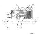
- the splice protection sleeve flange shown in Figure 1 comprises a flange body 1 defining two passages 2 for a cable C.
- the flange includes, as means for mechanically clamping the cable C, an annulus 3 extended by bars 4 uniformly spaced around the perimeter. These bars are resilient and each of them terminates in a claw 5 facing inwards and intended, when the bar is pushed back towards the axis XX' of the passage, to penetrate the cable C and mechanically damp it properly.
- a seal 6, for example made of an elastomer or of what is called a gel, is interposed between a moveable ring 7 and a fixed ring 8.
- the ring 8 is immobilized by penetrating a groove 9 made on the inner face of the body 1.
- the cable C is slipped between the two rings 7, 8.
- the ring 7 can move along the axis XX' as far as a stop 10 ( Figure 2) made on the body 1.
- a frustoconical threaded slide 11 is screwed into a tapping 12 in the body when it is slipped into the passage 2 via its larger transverse surface. It is inserted between the body 1 and the bars 4. As it is being gradually screwed in, it pushes back the annulus 3, which, in contact with the moveable ring 7, also pushes it back towards the fixed ring 8 until this moveable ring 7 butts against the stop 10. At this moment, the seal 6 highly compressed between the two rings 7 and 8 has flowed and ensures good sealing. When the slide 11 continues to be screwed in, it pushes the claws 4 inwards, these then catching on the cable C via the claws 5 and holding it properly in place.
- the slide 13 comes directly into contact with the moveable ring 14 which is itself in contact with the seal 15.
- the slide 13 compresses the seal 15 between the moveable ring 14 and the other, fixed ring and, at the same time, the slide 13 acts, via a ramp 16, on the bars 17 of an annulus 18 for damping the cable C.
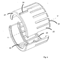
- the device shown in the figure 4 comprises a plastic ring 21 on which fingers 22, also made of plastic, are each mounted in the form of soft hinge.
- the free end of each finger 22 terminates in a claw 23 turned towards the longitudinal axis YY' of the ring.
- a rib 24 On the side of the plane where the fingers 22 do not lie, there is provided, on the outer face of the ring, a rib 24 intended to cooperate, by shape complementarity, with a groove 25 of another ring having a diameter greater than that of the ring 21.
- Each claw 22 has a bevel 26, the angle of the bevel being such that the end of the finger is approaching the axis YY'
Claims (2)
- Dispositif pour serrer un câble, charactérisé en ce qu'il comprend une bague (21) sur laquelle des doigts (22) sont montés individuellement sous la forme d'une charnière, l'extrémité libre de chaque doigt se terminant par une griffe (23) tournée vers l'axe longitunal YY' de ladite bague et, du côté du plan où les doigts (22) ne se trouvent pas, il est prévu un moyen (24) qui, par complémentarité de forme, est prévu pour coopérer avec un autre dispositif de serrage de forme identique mais ayant un diamètre de bague supérieur ou inférieur à une valeur égale à la dimension radiale la plus grande des doigts (22).
- Dispositif selon la revendication 1, caractérisé en ce que la portion d'un doigt (22) qui est la plus éloignée axialement de la bague (21) est biseautée, le haut du biseau étant plus proche de l'axe que le reste du biseau.
Applications Claiming Priority (5)
| Application Number | Priority Date | Filing Date | Title |
|---|---|---|---|
| FR0108601 | 2001-06-29 | ||
| FR0108598 | 2001-06-29 | ||
| FR0108598A FR2826795B1 (fr) | 2001-06-29 | 2001-06-29 | Manchon de protection d'epissure rapide a monter |
| FR0108601A FR2826793B1 (fr) | 2001-06-29 | 2001-06-29 | Dispositif de maintien d'un cable |
| EP02767170A EP1399997B1 (fr) | 2001-06-29 | 2002-06-20 | Fermeture de cable |
Related Parent Applications (1)
| Application Number | Title | Priority Date | Filing Date |
|---|---|---|---|
| EP02767170A Division EP1399997B1 (fr) | 2001-06-29 | 2002-06-20 | Fermeture de cable |
Publications (2)
| Publication Number | Publication Date |
|---|---|
| EP1536535A1 EP1536535A1 (fr) | 2005-06-01 |
| EP1536535B1 true EP1536535B1 (fr) | 2006-04-05 |
Family
ID=26213073
Family Applications (2)
| Application Number | Title | Priority Date | Filing Date |
|---|---|---|---|
| EP05004241A Expired - Lifetime EP1536535B1 (fr) | 2001-06-29 | 2002-06-20 | Dispositif de fermeture de câble |
| EP02767170A Expired - Lifetime EP1399997B1 (fr) | 2001-06-29 | 2002-06-20 | Fermeture de cable |
Family Applications After (1)
| Application Number | Title | Priority Date | Filing Date |
|---|---|---|---|
| EP02767170A Expired - Lifetime EP1399997B1 (fr) | 2001-06-29 | 2002-06-20 | Fermeture de cable |
Country Status (9)
| Country | Link |
|---|---|
| US (1) | US7005582B2 (fr) |
| EP (2) | EP1536535B1 (fr) |
| AT (2) | ATE304236T1 (fr) |
| BR (1) | BR0209581A (fr) |
| CA (1) | CA2444738A1 (fr) |
| DE (2) | DE60210511T2 (fr) |
| ES (2) | ES2248604T3 (fr) |
| MX (1) | MXPA03011939A (fr) |
| WO (1) | WO2003003534A1 (fr) |
Cited By (1)
| Publication number | Priority date | Publication date | Assignee | Title |
|---|---|---|---|---|
| CN102227080A (zh) * | 2011-04-14 | 2011-10-26 | 辽宁省电力有限公司盘锦供电公司 | 导线绝缘帽 |
Families Citing this family (47)
| Publication number | Priority date | Publication date | Assignee | Title |
|---|---|---|---|---|
| US7568943B2 (en) * | 2005-07-27 | 2009-08-04 | Corning Cable Systems Llc | Sealing and retaining cable attachment for telecommunications closures |
| DE102006036233B4 (de) * | 2006-08-03 | 2008-03-27 | Nkt Cables Gmbh | Freiluftendverschluss |
| TW201006059A (en) * | 2008-07-31 | 2010-02-01 | Acbel Polytech Inc | Water-proof assembly for wiring connections |
| US11294136B2 (en) | 2008-08-29 | 2022-04-05 | Corning Optical Communications LLC | High density and bandwidth fiber optic apparatuses and related equipment and methods |
| US8452148B2 (en) | 2008-08-29 | 2013-05-28 | Corning Cable Systems Llc | Independently translatable modules and fiber optic equipment trays in fiber optic equipment |
| EP2221932B1 (fr) * | 2009-02-24 | 2011-11-16 | CCS Technology Inc. | Dispositif de maintien pour câble ou ensemble à utiliser avec un câble |
| CA2755945A1 (fr) * | 2009-03-20 | 2010-09-23 | Drexan Energy Systems Inc. | Appareil de terminaison de cables et procedes afferents |
| US8699838B2 (en) | 2009-05-14 | 2014-04-15 | Ccs Technology, Inc. | Fiber optic furcation module |
| US9075216B2 (en) | 2009-05-21 | 2015-07-07 | Corning Cable Systems Llc | Fiber optic housings configured to accommodate fiber optic modules/cassettes and fiber optic panels, and related components and methods |
| US8712206B2 (en) | 2009-06-19 | 2014-04-29 | Corning Cable Systems Llc | High-density fiber optic modules and module housings and related equipment |
| CN106918885B (zh) | 2009-06-19 | 2021-09-21 | 康宁光缆系统有限责任公司 | 高密度和带宽光纤装置以及相关设备和方法 |
| US8625950B2 (en) | 2009-12-18 | 2014-01-07 | Corning Cable Systems Llc | Rotary locking apparatus for fiber optic equipment trays and related methods |
| US8593828B2 (en) * | 2010-02-04 | 2013-11-26 | Corning Cable Systems Llc | Communications equipment housings, assemblies, and related alignment features and methods |
| US8913866B2 (en) | 2010-03-26 | 2014-12-16 | Corning Cable Systems Llc | Movable adapter panel |
| CA2796221C (fr) | 2010-04-16 | 2018-02-13 | Ccs Technology, Inc. | Dispositif d'etancheite et de serrage pour cables de donnees |
| US8705926B2 (en) | 2010-04-30 | 2014-04-22 | Corning Optical Communications LLC | Fiber optic housings having a removable top, and related components and methods |
| US9075217B2 (en) | 2010-04-30 | 2015-07-07 | Corning Cable Systems Llc | Apparatuses and related components and methods for expanding capacity of fiber optic housings |
| US9720195B2 (en) | 2010-04-30 | 2017-08-01 | Corning Optical Communications LLC | Apparatuses and related components and methods for attachment and release of fiber optic housings to and from an equipment rack |
| US8879881B2 (en) | 2010-04-30 | 2014-11-04 | Corning Cable Systems Llc | Rotatable routing guide and assembly |
| US9519118B2 (en) | 2010-04-30 | 2016-12-13 | Corning Optical Communications LLC | Removable fiber management sections for fiber optic housings, and related components and methods |
| US8660397B2 (en) | 2010-04-30 | 2014-02-25 | Corning Cable Systems Llc | Multi-layer module |
| US9632270B2 (en) | 2010-04-30 | 2017-04-25 | Corning Optical Communications LLC | Fiber optic housings configured for tool-less assembly, and related components and methods |
| JP5600521B2 (ja) * | 2010-08-25 | 2014-10-01 | パナソニック株式会社 | 給電制御装置 |
| CN102375190B (zh) * | 2010-08-27 | 2014-01-22 | 鸿富锦精密工业(深圳)有限公司 | 光缆保护机构 |
| US8718436B2 (en) | 2010-08-30 | 2014-05-06 | Corning Cable Systems Llc | Methods, apparatuses for providing secure fiber optic connections |
| US9279951B2 (en) | 2010-10-27 | 2016-03-08 | Corning Cable Systems Llc | Fiber optic module for limited space applications having a partially sealed module sub-assembly |
| US9116324B2 (en) | 2010-10-29 | 2015-08-25 | Corning Cable Systems Llc | Stacked fiber optic modules and fiber optic equipment configured to support stacked fiber optic modules |
| US8662760B2 (en) | 2010-10-29 | 2014-03-04 | Corning Cable Systems Llc | Fiber optic connector employing optical fiber guide member |
| AU2011336747A1 (en) | 2010-11-30 | 2013-06-20 | Corning Cable Systems Llc | Fiber device holder and strain relief device |
| EP2671109A2 (fr) | 2011-02-02 | 2013-12-11 | Corning Cable Systems LLC | Ensembles de connecteurs de fibres optiques denses et connecteurs associés et câbles appropriés pour établir des connexions optiques pour des fonds de panier optiques dans des râteliers d'équipement |
| US20120246920A1 (en) * | 2011-03-31 | 2012-10-04 | John Mezzalingua Associates, Inc. | Split compression mid-span ground clamp |
| US8366459B2 (en) | 2011-03-31 | 2013-02-05 | John Mezzalingua Associates, Inc. | Compression style mid-span ground clamp |
| US8152537B1 (en) | 2011-03-31 | 2012-04-10 | John Mezzalingua Associates, Inc. | Split conductive mid-span ground clamp |
| US8636524B2 (en) | 2011-03-31 | 2014-01-28 | John Mezzalingua Associates, LLC | Split conductive mid-span ground clamp |
| US9008485B2 (en) | 2011-05-09 | 2015-04-14 | Corning Cable Systems Llc | Attachment mechanisms employed to attach a rear housing section to a fiber optic housing, and related assemblies and methods |
| AU2012275598A1 (en) | 2011-06-30 | 2014-01-16 | Corning Optical Communications LLC | Fiber optic equipment assemblies employing non-U-width-sized housings and related methods |
| US8953924B2 (en) | 2011-09-02 | 2015-02-10 | Corning Cable Systems Llc | Removable strain relief brackets for securing fiber optic cables and/or optical fibers to fiber optic equipment, and related assemblies and methods |
| US9038832B2 (en) | 2011-11-30 | 2015-05-26 | Corning Cable Systems Llc | Adapter panel support assembly |
| EP2863505A4 (fr) * | 2012-06-15 | 2016-02-17 | Martins Neto João | Presse-câble à indicateur de serrage |
| US9250409B2 (en) | 2012-07-02 | 2016-02-02 | Corning Cable Systems Llc | Fiber-optic-module trays and drawers for fiber-optic equipment |
| US9042702B2 (en) | 2012-09-18 | 2015-05-26 | Corning Cable Systems Llc | Platforms and systems for fiber optic cable attachment |
| ES2551077T3 (es) | 2012-10-26 | 2015-11-16 | Ccs Technology, Inc. | Unidad de gestión de fibra óptica y dispositivo de distribución de fibra óptica |
| US8985862B2 (en) | 2013-02-28 | 2015-03-24 | Corning Cable Systems Llc | High-density multi-fiber adapter housings |
| JP6156179B2 (ja) * | 2014-02-19 | 2017-07-05 | 株式会社オートネットワーク技術研究所 | クランプ |
| US9728949B2 (en) * | 2014-10-06 | 2017-08-08 | Richard A. Moore | Apparatus and method for preventing intrusion into splice closure |
| ES2952369T3 (es) | 2018-05-09 | 2023-10-31 | Afl Telecommunications Llc | Cierres a tope y bases para los mismos |
| US10996414B1 (en) | 2020-03-23 | 2021-05-04 | Afl Telecommunications Llc | Butt closures and bases therefor |
Family Cites Families (14)
| Publication number | Priority date | Publication date | Assignee | Title |
|---|---|---|---|---|
| US1745941A (en) * | 1928-04-04 | 1930-02-04 | Erie Malleable Iron Co | Conduit fitting |
| US2639313A (en) * | 1949-08-09 | 1953-05-19 | Jr Frederick G Street | High-voltage terminal connector |
| US2688651A (en) * | 1951-04-10 | 1954-09-07 | Us Rubber Co | Cable joint protector |
| US3055972A (en) * | 1958-07-03 | 1962-09-25 | Robert E Peterson | Fluid leakage seal for electric cables |
| GB1413673A (en) * | 1972-06-26 | 1975-11-12 | Bunker Ramo | Push-pull connector |
| US4116472A (en) * | 1974-04-25 | 1978-09-26 | Ludwig Peter Schmitt | Sealed wall lead-through means for cables in particular for junction boxes |
| FR2517132A1 (fr) * | 1981-11-24 | 1983-05-27 | Conducto | Dispositif d'etancheite et de serrage pour cables electriques |
| US4860838A (en) * | 1988-12-12 | 1989-08-29 | Drill Systems International Ltd. | Latching bit sub |
| DE3941269A1 (de) * | 1989-09-30 | 1991-04-11 | Stewing Kunststoff | Kabelmuffe zum verbinden und abzweigen von kabeln, insbesondere fernmeldekabeln |
| DE4135570C1 (fr) * | 1991-10-29 | 1992-11-05 | Stewing Kunststoffbetrieb Gmbh, 4270 Dorsten, De | |
| DE4238517A1 (de) * | 1992-11-14 | 1994-05-19 | Hummel Anton Verwaltung | Kabelverschraubung für Erdungs- oder Abschirm-Kabel |
| US5949022A (en) * | 1996-03-18 | 1999-09-07 | Lg Chemical Ltd. | Sealing structure for a single-bodied end cap of splice closure for optical cables |
| DE10010452A1 (de) * | 1999-12-02 | 2001-06-07 | Rxs Kabelgarnituren Gmbh & Co | Dichtungskörper für längsgeteilte Kabelgarnituren |
| DE10033911C1 (de) * | 2000-07-12 | 2002-04-04 | Hummel Anton Verwaltung | Anschlussarmatur für längliche Körper mit Spannzange |
-
2002
- 2002-06-20 MX MXPA03011939A patent/MXPA03011939A/es active IP Right Grant
- 2002-06-20 AT AT02767170T patent/ATE304236T1/de not_active IP Right Cessation
- 2002-06-20 DE DE60210511T patent/DE60210511T2/de not_active Expired - Lifetime
- 2002-06-20 DE DE60206045T patent/DE60206045T2/de not_active Expired - Lifetime
- 2002-06-20 AT AT05004241T patent/ATE322754T1/de not_active IP Right Cessation
- 2002-06-20 ES ES02767170T patent/ES2248604T3/es not_active Expired - Lifetime
- 2002-06-20 WO PCT/EP2002/007394 patent/WO2003003534A1/fr not_active Application Discontinuation
- 2002-06-20 US US10/482,186 patent/US7005582B2/en not_active Expired - Fee Related
- 2002-06-20 BR BR0209581-5A patent/BR0209581A/pt not_active IP Right Cessation
- 2002-06-20 CA CA002444738A patent/CA2444738A1/fr not_active Abandoned
- 2002-06-20 EP EP05004241A patent/EP1536535B1/fr not_active Expired - Lifetime
- 2002-06-20 ES ES05004241T patent/ES2262125T3/es not_active Expired - Lifetime
- 2002-06-20 EP EP02767170A patent/EP1399997B1/fr not_active Expired - Lifetime
Cited By (1)
| Publication number | Priority date | Publication date | Assignee | Title |
|---|---|---|---|---|
| CN102227080A (zh) * | 2011-04-14 | 2011-10-26 | 辽宁省电力有限公司盘锦供电公司 | 导线绝缘帽 |
Also Published As
| Publication number | Publication date |
|---|---|
| DE60206045T2 (de) | 2006-07-13 |
| US20040231881A1 (en) | 2004-11-25 |
| ES2262125T3 (es) | 2006-11-16 |
| CA2444738A1 (fr) | 2003-01-09 |
| ATE322754T1 (de) | 2006-04-15 |
| EP1536535A1 (fr) | 2005-06-01 |
| EP1399997A1 (fr) | 2004-03-24 |
| ATE304236T1 (de) | 2005-09-15 |
| DE60206045D1 (de) | 2005-10-13 |
| WO2003003534A1 (fr) | 2003-01-09 |
| EP1399997B1 (fr) | 2005-09-07 |
| MXPA03011939A (es) | 2005-06-06 |
| ES2248604T3 (es) | 2006-03-16 |
| US7005582B2 (en) | 2006-02-28 |
| DE60210511T2 (de) | 2007-01-11 |
| DE60210511D1 (de) | 2006-05-18 |
| BR0209581A (pt) | 2004-06-22 |
Similar Documents
| Publication | Publication Date | Title |
|---|---|---|
| EP1536535B1 (fr) | Dispositif de fermeture de câble | |
| AU667309B2 (en) | Cable seal | |
| GB2288495A (en) | Fixing device to anchor and seal an elongate member | |
| AU3736493A (en) | Heat shrinkable polymer hose and tubing clamp | |
| KR19990007980A (ko) | 폐쇄 장치 | |
| ES2144026T3 (es) | Estructura de abrazadera continua sin orejetas. | |
| US5516985A (en) | Cable end cap | |
| NZ329087A (en) | Cable clamping device has clamping arm on a body into which the object to be clamped is inserted, pushed into a sleeve with cutouts | |
| CA2149232A1 (fr) | Outil servant a faire tourner une tige | |
| RU96112108A (ru) | Корпус для кабеля | |
| WO1994024747A1 (fr) | Dispositif de blocage et d'etancheite destine a des cables | |
| EP1063463B8 (fr) | Raccord de tuyaux détachable | |
| EP1237227A3 (fr) | Connecteur pour conducteur électrique | |
| CA2056234A1 (fr) | Appareil servant a deposer les raccords de conduite souple | |
| GB2061631A (en) | Pushing elastic bodies onto elongate members | |
| JP2761630B2 (ja) | 引下線用端末キャップ | |
| EP1335802A1 (fr) | Couplage de securite | |
| AU6815600A (en) | Clamping device | |
| CA2087565A1 (fr) | Appareil servant a enlever les raccords de tuyau souple | |
| WO1996009673A1 (fr) | Dispositif d'etancheite | |
| FR2826795A1 (fr) | Manchon de protection d'epissure rapide a monter |
Legal Events
| Date | Code | Title | Description |
|---|---|---|---|
| PUAI | Public reference made under article 153(3) epc to a published international application that has entered the european phase |
Free format text: ORIGINAL CODE: 0009012 |
|
| 17P | Request for examination filed |
Effective date: 20050305 |
|
| AC | Divisional application: reference to earlier application |
Ref document number: 1399997 Country of ref document: EP Kind code of ref document: P |
|
| AK | Designated contracting states |
Kind code of ref document: A1 Designated state(s): AT BE CH CY DE DK ES FI FR GB GR IE IT LI LU MC NL PT SE TR |
|
| RAP1 | Party data changed (applicant data changed or rights of an application transferred) |
Owner name: CCS TECHNOLOGY, INC. |
|
| GRAP | Despatch of communication of intention to grant a patent |
Free format text: ORIGINAL CODE: EPIDOSNIGR1 |
|
| GRAS | Grant fee paid |
Free format text: ORIGINAL CODE: EPIDOSNIGR3 |
|
| GRAA | (expected) grant |
Free format text: ORIGINAL CODE: 0009210 |
|
| AKX | Designation fees paid |
Designated state(s): AT BE CH CY DE DK ES FI FR GB GR IE IT LI LU MC NL PT SE TR |
|
| AC | Divisional application: reference to earlier application |
Ref document number: 1399997 Country of ref document: EP Kind code of ref document: P |
|
| AK | Designated contracting states |
Kind code of ref document: B1 Designated state(s): AT BE CH CY DE DK ES FI FR GB GR IE IT LI LU MC NL PT SE TR |
|
| PG25 | Lapsed in a contracting state [announced via postgrant information from national office to epo] |
Ref country code: IT Free format text: LAPSE BECAUSE OF FAILURE TO SUBMIT A TRANSLATION OF THE DESCRIPTION OR TO PAY THE FEE WITHIN THE PRESCRIBED TIME-LIMIT;WARNING: LAPSES OF ITALIAN PATENTS WITH EFFECTIVE DATE BEFORE 2007 MAY HAVE OCCURRED AT ANY TIME BEFORE 2007. THE CORRECT EFFECTIVE DATE MAY BE DIFFERENT FROM THE ONE RECORDED. Effective date: 20060405 Ref country code: CH Free format text: LAPSE BECAUSE OF FAILURE TO SUBMIT A TRANSLATION OF THE DESCRIPTION OR TO PAY THE FEE WITHIN THE PRESCRIBED TIME-LIMIT Effective date: 20060405 Ref country code: FI Free format text: LAPSE BECAUSE OF FAILURE TO SUBMIT A TRANSLATION OF THE DESCRIPTION OR TO PAY THE FEE WITHIN THE PRESCRIBED TIME-LIMIT Effective date: 20060405 Ref country code: AT Free format text: LAPSE BECAUSE OF FAILURE TO SUBMIT A TRANSLATION OF THE DESCRIPTION OR TO PAY THE FEE WITHIN THE PRESCRIBED TIME-LIMIT Effective date: 20060405 Ref country code: LI Free format text: LAPSE BECAUSE OF FAILURE TO SUBMIT A TRANSLATION OF THE DESCRIPTION OR TO PAY THE FEE WITHIN THE PRESCRIBED TIME-LIMIT Effective date: 20060405 Ref country code: NL Free format text: LAPSE BECAUSE OF FAILURE TO SUBMIT A TRANSLATION OF THE DESCRIPTION OR TO PAY THE FEE WITHIN THE PRESCRIBED TIME-LIMIT Effective date: 20060405 |
|
| REG | Reference to a national code |
Ref country code: GB Ref legal event code: FG4D |
|
| REG | Reference to a national code |
Ref country code: CH Ref legal event code: EP |
|
| REG | Reference to a national code |
Ref country code: IE Ref legal event code: FG4D |
|
| REF | Corresponds to: |
Ref document number: 60210511 Country of ref document: DE Date of ref document: 20060518 Kind code of ref document: P |
|
| PG25 | Lapsed in a contracting state [announced via postgrant information from national office to epo] |
Ref country code: IE Free format text: LAPSE BECAUSE OF NON-PAYMENT OF DUE FEES Effective date: 20060620 |
|
| PG25 | Lapsed in a contracting state [announced via postgrant information from national office to epo] |
Ref country code: MC Free format text: LAPSE BECAUSE OF NON-PAYMENT OF DUE FEES Effective date: 20060630 |
|
| PG25 | Lapsed in a contracting state [announced via postgrant information from national office to epo] |
Ref country code: DK Free format text: LAPSE BECAUSE OF FAILURE TO SUBMIT A TRANSLATION OF THE DESCRIPTION OR TO PAY THE FEE WITHIN THE PRESCRIBED TIME-LIMIT Effective date: 20060705 Ref country code: SE Free format text: LAPSE BECAUSE OF FAILURE TO SUBMIT A TRANSLATION OF THE DESCRIPTION OR TO PAY THE FEE WITHIN THE PRESCRIBED TIME-LIMIT Effective date: 20060705 |
|
| PG25 | Lapsed in a contracting state [announced via postgrant information from national office to epo] |
Ref country code: PT Free format text: LAPSE BECAUSE OF FAILURE TO SUBMIT A TRANSLATION OF THE DESCRIPTION OR TO PAY THE FEE WITHIN THE PRESCRIBED TIME-LIMIT Effective date: 20060905 |
|
| NLV1 | Nl: lapsed or annulled due to failure to fulfill the requirements of art. 29p and 29m of the patents act | ||
| REG | Reference to a national code |
Ref country code: CH Ref legal event code: PL |
|
| ET | Fr: translation filed | ||
| REG | Reference to a national code |
Ref country code: ES Ref legal event code: FG2A Ref document number: 2262125 Country of ref document: ES Kind code of ref document: T3 |
|
| PLBE | No opposition filed within time limit |
Free format text: ORIGINAL CODE: 0009261 |
|
| STAA | Information on the status of an ep patent application or granted ep patent |
Free format text: STATUS: NO OPPOSITION FILED WITHIN TIME LIMIT |
|
| 26N | No opposition filed |
Effective date: 20070108 |
|
| PG25 | Lapsed in a contracting state [announced via postgrant information from national office to epo] |
Ref country code: GR Free format text: LAPSE BECAUSE OF FAILURE TO SUBMIT A TRANSLATION OF THE DESCRIPTION OR TO PAY THE FEE WITHIN THE PRESCRIBED TIME-LIMIT Effective date: 20060706 |
|
| PG25 | Lapsed in a contracting state [announced via postgrant information from national office to epo] |
Ref country code: TR Free format text: LAPSE BECAUSE OF FAILURE TO SUBMIT A TRANSLATION OF THE DESCRIPTION OR TO PAY THE FEE WITHIN THE PRESCRIBED TIME-LIMIT Effective date: 20060405 Ref country code: LU Free format text: LAPSE BECAUSE OF NON-PAYMENT OF DUE FEES Effective date: 20060620 |
|
| PG25 | Lapsed in a contracting state [announced via postgrant information from national office to epo] |
Ref country code: CY Free format text: LAPSE BECAUSE OF FAILURE TO SUBMIT A TRANSLATION OF THE DESCRIPTION OR TO PAY THE FEE WITHIN THE PRESCRIBED TIME-LIMIT Effective date: 20060405 |
|
| PGFP | Annual fee paid to national office [announced via postgrant information from national office to epo] |
Ref country code: GB Payment date: 20130627 Year of fee payment: 12 |
|
| PGFP | Annual fee paid to national office [announced via postgrant information from national office to epo] |
Ref country code: FR Payment date: 20130702 Year of fee payment: 12 |
|
| PGFP | Annual fee paid to national office [announced via postgrant information from national office to epo] |
Ref country code: BE Payment date: 20130627 Year of fee payment: 12 |
|
| GBPC | Gb: european patent ceased through non-payment of renewal fee |
Effective date: 20140620 |
|
| REG | Reference to a national code |
Ref country code: FR Ref legal event code: ST Effective date: 20150227 |
|
| PG25 | Lapsed in a contracting state [announced via postgrant information from national office to epo] |
Ref country code: FR Free format text: LAPSE BECAUSE OF NON-PAYMENT OF DUE FEES Effective date: 20140630 Ref country code: GB Free format text: LAPSE BECAUSE OF NON-PAYMENT OF DUE FEES Effective date: 20140620 |
|
| PGFP | Annual fee paid to national office [announced via postgrant information from national office to epo] |
Ref country code: DE Payment date: 20150629 Year of fee payment: 14 Ref country code: ES Payment date: 20150626 Year of fee payment: 14 |
|
| REG | Reference to a national code |
Ref country code: DE Ref legal event code: R119 Ref document number: 60210511 Country of ref document: DE |
|
| PG25 | Lapsed in a contracting state [announced via postgrant information from national office to epo] |
Ref country code: DE Free format text: LAPSE BECAUSE OF NON-PAYMENT OF DUE FEES Effective date: 20170103 |
|
| PG25 | Lapsed in a contracting state [announced via postgrant information from national office to epo] |
Ref country code: BE Free format text: LAPSE BECAUSE OF NON-PAYMENT OF DUE FEES Effective date: 20140630 |
|
| PG25 | Lapsed in a contracting state [announced via postgrant information from national office to epo] |
Ref country code: ES Free format text: LAPSE BECAUSE OF NON-PAYMENT OF DUE FEES Effective date: 20160621 |
|
| REG | Reference to a national code |
Ref country code: ES Ref legal event code: FD2A Effective date: 20181203 |