EP1536528B1 - Elektrischer verbinder für eine drahtlose elektrische vorrichtung - Google Patents
Elektrischer verbinder für eine drahtlose elektrische vorrichtung Download PDFInfo
- Publication number
- EP1536528B1 EP1536528B1 EP03783897A EP03783897A EP1536528B1 EP 1536528 B1 EP1536528 B1 EP 1536528B1 EP 03783897 A EP03783897 A EP 03783897A EP 03783897 A EP03783897 A EP 03783897A EP 1536528 B1 EP1536528 B1 EP 1536528B1
- Authority
- EP
- European Patent Office
- Prior art keywords
- contact
- power supply
- socket
- sheet
- plug
- Prior art date
- Legal status (The legal status is an assumption and is not a legal conclusion. Google has not performed a legal analysis and makes no representation as to the accuracy of the status listed.)
- Expired - Lifetime
Links
- 238000010586 diagram Methods 0.000 description 14
- NJPPVKZQTLUDBO-UHFFFAOYSA-N novaluron Chemical compound C1=C(Cl)C(OC(F)(F)C(OC(F)(F)F)F)=CC=C1NC(=O)NC(=O)C1=C(F)C=CC=C1F NJPPVKZQTLUDBO-UHFFFAOYSA-N 0.000 description 6
- 230000000694 effects Effects 0.000 description 5
- 230000001419 dependent effect Effects 0.000 description 1
- 238000009434 installation Methods 0.000 description 1
- 238000004519 manufacturing process Methods 0.000 description 1
Images




Classifications
-
- H—ELECTRICITY
- H01—ELECTRIC ELEMENTS
- H01R—ELECTRICALLY-CONDUCTIVE CONNECTIONS; STRUCTURAL ASSOCIATIONS OF A PLURALITY OF MUTUALLY-INSULATED ELECTRICAL CONNECTING ELEMENTS; COUPLING DEVICES; CURRENT COLLECTORS
- H01R13/00—Details of coupling devices of the kinds covered by groups H01R12/70 or H01R24/00 - H01R33/00
- H01R13/66—Structural association with built-in electrical component
- H01R13/70—Structural association with built-in electrical component with built-in switch
- H01R13/703—Structural association with built-in electrical component with built-in switch operated by engagement or disengagement of coupling parts, e.g. dual-continuity coupling part
-
- H—ELECTRICITY
- H01—ELECTRIC ELEMENTS
- H01R—ELECTRICALLY-CONDUCTIVE CONNECTIONS; STRUCTURAL ASSOCIATIONS OF A PLURALITY OF MUTUALLY-INSULATED ELECTRICAL CONNECTING ELEMENTS; COUPLING DEVICES; CURRENT COLLECTORS
- H01R35/00—Flexible or turnable line connectors, i.e. the rotation angle being limited
- H01R35/04—Turnable line connectors with limited rotation angle with frictional contact members
Definitions
- the present invention is related to an electrical connector, especially related to a rotatable connector for use with a cordless and detachable electrical appliance, such as electrical heater pot, cordless frying pan, cordless electrical flatiron and so on.
- a cordless and detachable electrical appliance such as electrical heater pot, cordless frying pan, cordless electrical flatiron and so on.
- CN1135270A corresponding document WO 9508204 A1 ("Cordless electrical appliances and connectors therefore"), disclosing the preambles of claims 1 and 10, provides a rotatable electrical connector, including an electronegative tie-in(plug)and an electropositive tie-in (socket).
- the plug includes a center conducting pillar receiving terminal lug and a ring receiving terminal lug being concentric with that terminal lug.
- In the front of the socket there is an opening for accepting the center pillar receiving terminal lugs and the ring receiving terminal lugs of the plug.
- the socket has a separate power supply contact for bonding with the receiving terminal lugs.
- This design makes the plug in the bottom center of electrical appliance near its barycenter or at the same plumb line with it, and freely rotates relative to power supply pedestal without impeding the electrical connecting effect from the horizontal direction, which makes the electrical appliance setting in the power supply pedestal more firm and gets better connecting effect.
- the socket is being power supplied continuously, that is, the contact sheet in the center hole or ring grooves is being electrified continuously. So, for avoiding getting an electric shock accident and assuring the connecting effect, the diameter of the center hole and ring groove's width must be very small, normally, no more than 3mm, which requires the user to align the plug and socket straight carefully when using. Therefore, it makes the user's inconvenience; on the other hand, because it limits the size of supply pedestal, when the power supply to the electrical appliance is large and a larger size of connector is needed, it's hard to realize.
- This invention addresses the limitations in the prior art described above. It provides a new connector for cordless electrical appliance, which keeps the connecting contact sheet of socket connected with plug being power off all the time while the plug is not inserted.
- EP 1 253 679 which was published after the priority date of the present application but which has an earlier filing date describes an electrical connector for use with, for example, a cordless kettle. It describes a switching mechanism whereby electrical power to terminals in the power supply base of the kettle is inhibited whilst no kettle stands on the base. In this state contacts to supply power to such terminals are held apart. When a kettle is placed on the base this operates actuators allowing the spaced contacts to move into contact with one another such that power can be supplied to the terminals.
- the actuators are in the form of pins which are separate from the electrical contacts between the base and the kettle.
- an electrical connector as claimed in claim 1.
- the present device sets up two pair of mutually corresponding power supply contact sheet teams, and when the plug isn't inserted into the socket, in the power supply contact sheet team at least one of them connected with the live wire or zero line of power supply and its corresponding power supply contact sheet keeps normally open, which makes that the visible power supply contact sheet of the socket surface is not electrified all the time, and also not only safety in use, but also facilitative connection on account of the unrestricted width and depth, even inserting incliningly, the effect is the same.
- the present arrangement will make it possible to design, manufacture and utilize larger power electrical connector, and widen its applied field dramatically, support the variegated development of products such as electrical pot and electrical frying pan.
- Example one as shown in Figs 1 , 2 , includes a plug 100 and a socket 200 that are interconnectable and relatively rotatable.
- a plughole In the center of the socket's upper face there is a plughole and a number of ring grooves being concentric with the plughole, inside the plughole is a center power supply receiving pillar 202, inside and outside the ring groove there are power supply contact sheets 201, 203, inside the power supply contact's 201 underside there is an immovable contact 201a extended outwards, and outside the power supply contact 203 there is an immovable contact 203a.
- the socket 200 On the underside of the socket 200 there are three corresponding power supply contacts 301, 302, 303 all in the form of movable contact sheets, which correspond to the power supply contact sheet 201, the power supply receiving pillar 202 and the power supply contact sheet 203 respectively; the power supply contact sheet 302 is connected with the earth wire of the power supply and pressed against the power supply receiving pillar 202 all the time.
- the power supply contacts 301, 303 are respectively connected with the live wire and the zero line of the power supply, and on the one side of the supply contact sheet 301 there is a movable contact 301a, opposite to a immovable contact 201a of the power supply contact 201; on the one side of power supply contact sheet 303 there is a movable contact 303a, opposite to an immovable contact 203a of the power supply contact sheet 203.
- the isolating pushrod 304 is in the horizontal direction, whose central section is connected with the root of socket's center receiving pillar (202), on the both sides of which there is an underside warp, with a slope side, and the half part of its underside touches with power supply contact sheet 301, 303's corresponding parallel slope; which forms the contact switching mechanism.
- the isolating pushrod 304 under the action of its two sides acts on two power supply contact sheets 301, 303 at the same ti me, however, in practical application, it can act one of the power supply contact sheets only through one side, and another power supply contact is connected directly with its corresponding line of power supply.
- the socket 210 there are three corresponding power supply contacts 311, 312, 313 all in the form of movable contact sheets, which correspond to the power supply contact sheet 211, the power supply receiving pillar 212 and the power supply contact sheet 213 respectively;
- the power supply contact sheet 312 is connected with the ground wire of the power supply and pressed against power supply receiving pillar 212 all the time;
- the power supply contacts 311, 313 are in the vertical direction, connected with live wire and zero line of power supply respectively, and that, on one side of the supply contact sheet 311 there is a movable contact 311a, opposite to the immovable contact 211a of the power supply contact 211; on one side of power supply contact sheet 313 there is a movable contact 313a, opposite to the immovable contact 213a of the power supply contact sheet 213.
- the insulating sheet whose section is of inverted T-type and whose underside is held by a reset spring 315 is under the power supply receiving pillar 212. On its both sides there are power supply contact sheets 311, 313. And the upside of the insulating sheet 314 is connected with the root of the socket's center receiving pillar 212.
- the receiving contact sheet 111 of the plug touches the power supply contact sheets 211 of the socket through contact 111a
- the receiving plug pillar 113 touches the power supply contact sheet 213
- the plug's center plug pillar 112 presses the socket's center receiving pillar 212 down
- the isolating sheet 314 moves down with it, causing the vertical power supply contact sheets 311,313 to move towards power supply contact sheets 211, 213 respectively until movable contacts 311a, 313a respectively touch immovable contacts 211a, 213a.
- the isolating sheet 314 under the action of its both sides acts on two power supply contact sheets 311,313 at the same time, however, in practical application, it can act one of the power supply contact sheets only through one side, and another power supply contact is connected directly with its corresponding line of power supply.
- a center power supply receiving pillar 222 inside the plughole is a center power supply receiving pillar 222, at the bottom of the ring groove there are ring power supply contact sheets 221, 223, with a underside extended outwards and a tortuous end where there are immovable contacts 221a, 223a.
- the socket 220 there are three corresponding power supply contacts sheets 321, 322, 323 all in he form of movable contact sheets, which correspond to the power supply contact sheet 221, the power supply receiving pillar 222 and power supply contact sheet 223; the power supply contact sheet 322 is connected with the ground wire of the power supply and pressed against the power supply receiving pillar 222 all the time; on the immovable contacts 221a, 223a the power supply contacts 321, 323 are connected with the live wire and the zero line of power supply respectively, and that on, the underside of supply contact sheets 321, 323 there are movable contacts 321a, 323a, corresponding to immovable contacts 221a, 223a respectively.
- the isolating pushrod 324 is in horizontal direction, whose central section is connected with the root of socket's center receiving pillar 222 and whose two sides are connected with the power supply contact sheets 321, 323 respectively.
- the plug 120 there is a bulgy ring wall 124 that can be plugged into the socket's 220 ring groove, and in the center of which there is a receiving plug pillar 122, corresponding to socket's power supply pillar 222; on both sides of which there are two receiving plug pillars 121, 123, corresponding to socket's power supply contact sheets 221, 223 respectively.
- the receiving plug pillar 121, 123 of the plug touches the power supply contact sheets 221, 223 of the socket respectively.
- the plug's center plug pillar 122 presses the socket's center receiving pillar 222 down, the isolating pushrod 324 then moves down with it, under the action of vertical power supply contact sheets 321, 323, which causes the vertical power supply contact sheets 321, 323 to move towards power supply immovable contacts 221a, 223a respectively until movable contacts 321a, 323a touch immovable contacts 221a, 223a respectively.
- the isolating pushrod 324 under the action of its both sides acts on two power supply contact sheets 321, 323 at the same time, however, in practical application, it can act one of the power supply contact sheets only through one side, and another power supply contact is connected directly with its corresponding line of power supply.
- a plughole and a ring grooves being concentric with the plughole inside the plughole is a center power supply plug pillar 232 , on the inside and the outside of the ring groove there are ring power supply contact sheets 231, 233, with an underside extended outwards and a tortuous end where there are immovable contacts 231a, 233a.
- the socket 230 On the underside of the socket 230 there are three corresponding power supply contacts sheets 331, 332, 333 all in the form of movable contact sheets, which correspond to the power supply contact sheet 231, the power supply receiving pillar 232 and the power supply contact sheet 233 respectively; the power supply contact sheet 332 is connected with the ground wire of the power supply and pressed against the power supply receiving pillar 232 all the time; the power supply contacts 331, 333 which are in parallel and connected with the live wire and the zero line of power supply respectively, one side of which is fixed on the shell of the socket, on another side there are movable contacts 331a, 333a, which are under the immovable contacts 231a, 233a and opposite to them respectively.
- the isolating lever 334 is of inverted T-type, one side of the vertical rod of which is connected with the root of socket's center receiving pillar 232 and the horizontal rod of which is under the movable contacts 331a, 333a.
- a ring bulgy wall 134 that can be pluged into the socket's 230 ring groove, and in the center of which there is a receiving plug pillar 132, corresponding to socket's power supply pillar 232; on both sides of which there are two receiving plug pillars 131, 133, and on the underside of it there are contacts 131a, 133a, corresponding to socket's power supply contact sheets 231, 233 respectively.
- the isolating lever 334 under the action of its both sides acts on two power supply contact sheets 331, 333 at the same time, however, in practical application, it can act one of the power supply contact sheets only through one side, and another power supply contact is connected directly with its corresponding line of the power supply.
- a center power supply plug pillar 242 inside the plughole is a center power supply plug pillar 242, on the inside and outside of the ring groove there are ring power supply contact sheets 241, 243, with an underside extended downwards and a tortuous end where there are immovable contacts 241 a, 243a.
- the socket 240 On the underside of the socket 240 there are three corresponding power supply contacts sheets 341, 342, 343 all in the form of movable contact sheets, which correspond to the power supply contact sheet 241, the power supply receiving pillar 242 and the power supply contact sheet 243 respectively; the power supply contact sheet 342 is connected with the ground wire of the power supply and pressed against the power supply receiving pillar 242 all the time; the power supply contacts 341, 343 which are in parallel are connected with the live wire and the zero line of the power supply respectively, one side of which is fixed on the shell of the socket, on another side there are movable contacts 341a, 343a, which are under immovable contacts 241a, 243a and opposite to them respectively, and its central section is held by pivot
- the insulating sliding sheet 344 is lambdoidal, see Fig. 13 . Its upside runs thoroughly through the bottom of socket's concentric ring groove and it can slide up and down. On its two undersides there are power supply contacts 341, 343 near their fixed parts above respectively.
- a ring bulgy wall 144 that can be plugged into socket's 240 ring groove, and in the center of which there is a receiving plug pillar 142, corresponding to socket's power supply pillar 242; on two sides of which there are two receiving contact sheets 141, 143, and on the underside of which there are contacts 141a, 143a, corresponding to socket's power supply contact sheets 241, 243 respectively.
- the receiving plug pillars 141, 143 of the plug through power supply contacts 141a, 143a of plug touch the power supply contact sheets 241, 243 of the socket respectively
- the plug's center plug pillar 142 touches with the center receiving pillar 242; at this time, the ring bulgy wall 144 of socket 140 inserts into the ring groove of the socket 240, the insulating sheet 344 slides down under the action of the ring groove wall's 144 end, pressing the bacilliform movable contact sheets 341, 343, raising the movable contact under the action of the lever until movable contacts 341a, 343a touch immovable contacts 241a, 243a respectively.
- the isolating sliding sheet 344 under the action of its both sides acts on two power supply contact sheets 341, 343 at the same time, however, in practical application, it can act on one of the power supply contact sheets only through one side, and another power supply contact is connected directly with its corresponding line of the power supply.
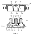
- a center power supply contact sheet 252 on the tortuous end underside extended outwards there is a immovable contact 252a; inside the external ring groove there is a power supply contact sheet 251, with an underside downwards end; inside the internal ring groove there is a power supply contact sheet 253, and on the underside outstretched and tortuous end there is a immovable contact 253a.
- the socket 250 there are one immovable power supply contact sheet 351 and two power supply contact sheets 352, 353 in the movable contact sheet form, which correspond to power supply contact sheet 251, 252, 253 respectively;
- the power supply contact sheet 351 is connected with the underside outstreched end of the power supply contact sheet 251 all the time and the ground wire of the power supply;
- the power supply contacts 352, 353 are connected with the live wire and the zero line of electric line respectively, they are set in parallel with one above another, with respective movable contacts 352a, 353a set in their upsides, and opposite to immovable contacts 252a, 253a respectively.
- the plug 150 there is a bulgy ring wall 154 that can be plugged into the socket's 250 ring groove, and in the center of which there is a receiving plug pillar 152, corresponding to socket's power supply pillar 252; on both sides of which there is a V-type receiving contact sheet 151 and a receiving plug pillar 153, corresponding to socket's power supply contact sheets 251, 253 respectively.
- a cuneiform insulating sheet 354 holds the movable contact end of the power supply contacts 352, 353 on its slope, and its inside is held by a reset spring 355, forming an outward horizontal moving trend.
- the receiving contact sheet 151 and the receiving plug pillars 152, 153 of the plug touch the power supply contacts 251, 252, 253 of the socket respectively; at this moment, the cuneiform insulating sheet 354 under the action of plug's ring external wall 155 moves down inwards laterally and pushes movable contacts 352, 353 on the slope upwards until movable contacts 352a, 353a touch immovable contacts 252a, 253a.
- the cuneiform insulating sheet 354 via its slope under the action of its two sides acts on both power supply contact sheets 352, 353 at the same time, however, in practical application, it can act one of the power supply contact sheets only through one side, and another power supply contact is connected directly with its corresponding line of the power supply.
Landscapes
- Details Of Connecting Devices For Male And Female Coupling (AREA)
- Connector Housings Or Holding Contact Members (AREA)
Claims (10)
- Ein elektrischer Verbinder für eine drahtlose elektrische Anwendung, umfassend:einen Stecker (100, 110, 120, 130, 140) und eine Steckdose (200, 210, 220, 230, 240), die miteinander verbindbar und relativ drehbar sind, während die Mitte der oberen Fläche der Steckdose ein Steckerloch mit mindestens einer Ringnut aufweist, die konzentrisch mit dem Steckerloch ist, während Energieversorgungskabelschuhe innerhalb des Steckerlochs sowie der mindestens einen Ringnut entsprechend vorhanden sind, und der Stecker ist bereitgestellt mit mittigen Aufnahmekabelschuhen und umfänglichen Kabelschuhen, die mit den Energieversorgungskabelschuhen innerhalb der Mitte des Steckerlochs und der mindestens einen Ringnut der Steckdose entsprechend in Eingriff bringbar sind, während die Steckdose weiterhin umfasstmindestens ein Energieversorgungskontaktblech (301, 303, 311, 313, 321, 323, 331, 333, 341, 343), das mit einem stromführenden Draht oder einem Nullleiter einer Energieversorgung entsprechend den Energieversorgungskabelschuhen (201, 203, 211, 213, 221, 223, 231, 233, 241, 243) innerhalb der mindestens einen konzentrischen Ringnut verbunden ist, sowie mindestens einen Kontaktumschaltmechanismus, der die Kontakte zwischen dem Energieversorgungskontaktblech und den entsprechenden Aufnahmekabelschuhen üblicherweise offen hält, wenn der Stecker (100) nicht in die Steckdose (200) eingesetzt ist und bewirkt, dass sich das üblicherweise geöffnete Kontaktpaar schließt und unter Betätigung des Steckers elektrisch verbunden wird, wenn der Stecker in die Steckdose eingesetzt wird, und der entsprechende umfängliche Aufnahmekabelschuh des Steckers (101, 103, 111, 113, 121, 123, 131, 133, 141, 143) ist entweder ein Steckerstift oder ein Kontaktblech, während die Energieversorgungskabelschuhe der Steckdose entsprechend ein Aufnahmestift oder ein Kontaktblech sind, dadurch gekennzeichnet, dassder mittige Aufnahmekabelschuh des Steckers ein Steckerstift (102, 112, 122, 132, 142) ist, während der entsprechende Energieversorgungskabelschuh (202, 212, 222, 232, 242) innerhalb des mittigen Steckerlochs der Steckdose in Eingriff mit dem Erdungsdraht der Energieversorgung steht und der Kontaktumschaltmechanismus durch den Energieversorgungskabelschuh innerhalb des mittigen Steckerlochs der Steckdose (200) versorgt wird.
- Ein elektrischer Verbinder für eine drahtlose elektrische Anwendung gemäß Anspruch 1, in dem der Kontaktumschaltmechanismus umfasst: eine horizontale Isolierstößelstange (304), während unter der Stößelstange das Energieversorgungskontaktblech (303) in derselben Richtung wie die Stößelstange (304) angeordnet ist, wobei die Mitte der Isolierstößelstange (304) mit dem Boden des mittigen Aufnahmestifts (202) der Steckdose verbunden ist, während am Ende der Stößelstange ein Überwurf mit einer geneigten äußeren Ebene angeordnet ist, die eine entsprechende parallele Schräge des Energieversorgungskontaktblechs (301, 303) kontaktiert, wobei auf dem Energieversorgungskontaktblech (301, 303) ein bewegbarer Kontakt (301a, 303a) angeordnet ist, der einem unbewegbaren Kontakt (201a, 203a) unter der Außenseite des Energieversorgungskontaktblechs (201, 203) der Steckdose der mindestens einen konzentrischen Ringnut entspricht, und in dem, wenn die Isolierstößelstange (304) sich abwärts bewegt, beispielsweise durch die Wirkung der Schräge, sich das Energieversorgungskontaktblech (301,303) in Richtung des unbewegbaren Kontakts (201a, 203a) bewegt, bis der bewegbare Kontakt (301a, 303a) den unbewegbaren Kontakt (201a, 203a) berührt.
- Ein elektrischer Verbinder für eine drahtlose elektrische Anwendung gemäß Anspruch 1, in dem der Kontaktumschaltmechanismus umfasst: einen Isolierblock (314), dessen Querschnitt umgedreht T-förmig ist, sowie ein vertikal bewegbares Kontaktblech (311, 313), wobei die obere Fläche des Isolierblocks mit dem Boden des mittigen Aufnahmestifts (212) der Steckdose verbunden ist, dessen Unterseite durch eine Rückstellfeder (315) gestützt wird, während auf dem vertikal bewegbaren Kontaktblech (311, 313) ein bewegbarer Kontakt (311a, 313a) bereitgestellt ist, der mit einem stromführenden Draht oder einem Nullleiter verbunden ist, wobei der bewegbare Kontakt einem unbewegbaren Kontakt (211a, 213a) unter der Außenseite des Energieversorgungskontaktblechs (211, 213) der Steckdose der mindestens einen konzentrischen Ringnut entspricht, und in dem, wenn der umgedreht T-förmige Isolierblock (314) sich nach unten bewegt, sich das vertikal bewegbare Kontaktblech (311, 313) auswärts in Richtung des unbewegbaren Kontakts (211a, 213a) neigt, bis der bewegbare Kontakt (311a, 313a) den unbewegbaren Kontakt berührt.
- Ein elektrischer Verbinder für eine drahtlose elektrische Anwendung gemäß Anspruch 1, in dem der Kontaktumschaltmechanismus umfasst: eine horizontale Stößelstange (324), deren mittiger Bereich mit dem Boden des mittigen Aufnahmestifts (222) der Steckdose verbunden ist, während auf beiden Seiten der Isolierstößelstange (324) ein bewegbarer Kontakt (321a, 323a) vorhanden ist, der mit einem stromführenden Draht oder einem Nullleiter entsprechend verbunden ist, dementsprechend ist das untere Ende des Energieversorgungskontaktblechs (221, 223) innerhalb der mindestens einen konzentrischen Ringnut der Steckdose unter den bewegbaren Kontakt (321a, 323a) gebogen, um einen unbewegbaren Kontakt (221a, 223a) genau entgegengesetzt zu dem bewegbaren Kontakt (321a, 323a) bereitzustellen, und in dem, wenn die Isolierstößelstange (324) sich nach unten bewegt, sich der bewegbare Kontakt (321a, 323a) mit ihr bewegt, bis er den unbewegbaren Kontakt (221a, 223a) berührt.
- Ein elektrischer Verbinder für eine drahtlose elektrische Anwendung gemäß Anspruch 1, in dem der Kontaktumschaltmechanismus umfasst: einen Isolierhebel (334) und ein bewegbares Kontaktblech (321, 323), während ein Ende des bewegbaren Kontaktblechs (331, 333) an der Steckdosenhülle befestigt ist und ein anderes Ende des bewegbaren Kontaktblechs einen bewegbaren Kontakt (331a, 333a) aufweist, der entsprechend unter dem umhüllten Ende des Steckdosenenergieversorgungskontaktblechs (231, 233) der mindestens einen konzentrischen Ringnut aufgesetzt ist, um einen unbewegbaren Kontakt (231a, 233a) auf der Hülle genau gegenüber dem bewegbaren Kontakt (331a, 333a) bereitzustellen, während ein Ende des Isolierhebels (334) mit dem Boden des mittigen Aufnahmestifts (232) der Steckdose verbunden ist, wobei ein anderes Ende des Hebels (324) sich unter dem Ende des bewegbaren Kontaktblechs (331, 333) angeordnet ist, auf dem der bewegbare Kontakt angeordnet ist, und in dem, wenn der mittige Aufnahmestift (232) der Steckdose sich nach unten bewegt, der Isolierhebel umschlägt und den bewegbaren Kontakt (331a, 333a) des bewegbaren Kontaktblechs (331, 333) anhebt, bis der bewegbare Kontakt (331a, 333a) den unbewegbaren Kontakt (231a, 233a) berührt.
- Ein elektrischer Verbinder für eine drahtlose elektrische Anwendung gemäß Anspruch 1, in dem der Kontaktumschaltmechanismus umfasst ein Isoliergleitblech (344) und ein bewegbares Kontaktblech (341, 343), während ein Ende des bewegbare Kontaktblechs (341, 343) an der Steckdosenhülle befestigt ist und eine andere Seite des bewegbaren Kontaktblechs einen bewegbaren Kontakt (341a, 343a) aufweist, wobei ein mittiger Bereich des bewegbaren Kontaktblechs durch einen Schwenkzapfen gehalten wird, der entsprechend unter einem umhüllten Ende des Energieversorgungskontaktblechs (241, 243) der Steckdose der mindestens einen konzentrischen Ringnut aufgesetzt ist, so dass ein unbewegbarer Kontakt (241a, 243a) auf der Hülle genau entgegengesetzt zu dem bewegbaren Kontakt (3411a, 343a) angeordnet ist, während das Isoliergleitblech (344) auf dem Boden der mindestens einen konzentrischen Ringnut der Steckdose aufgesetzt ist, um in der Lage zu sein, nach oben und unten zu rutschen, wobei die Unterseite des Gleitblechs (344) gegen den Teil des bewegbaren Kontaktblechs in der Nähe des befestigten Endes gedrückt wird, und in dem, wenn das Isoliergleitblech (344) sich nach unten bewegt, das Blech das bewegbare Kontaktblech unter der Betätigung des Blechs, das den bewegbaren Kontakt (341a, 343a) anhebt, herunterdrückt, bis es den unbewegbaren Kontakt (241a, 243a) berührt.
- Ein elektrischer Verbinder für eine drahtlose elektrische Anwendung gemäß Anspruch 1, der lediglich eine konzentrische Ringnut in der Steckdose mit entsprechend einer Ringenergieversorgungskontaktinnenseite (203) und -außenseite (201) aufweist, während der Aufnahmekabelschuh der Steckdose ebenso ein Kontaktblech entsprechend aufweist und entsprechend dem inneren Aufnahmekontaktblech der Ringnut der Steckdose weist er einen gewölbten Kontakt (103a) innerhalb von ihm auf und entsprechend der Außenseite des Aufnahmekontaktblechs der Ringnut der Steckdose weist er einen gewölbten Kontakt (101a) auf.
- Ein elektrischer Verbinder für eine drahtlose elektrische Anwendung gemäß Anspruch 1, in dem die Steckdose umfasst: zwei konzentrische Ringnute darin, mit einem Energieversorgungskontaktblech entsprechend außerhalb von diesen, während der umfängliche Aufnahmekabelschuh in dem Stecker ein Kontaktblech aufweist und auf einer Seite der entsprechenden Ringnut ist ein gewölbter Kontakt angeordnet.
- Ein elektrischer Verbinder für eine drahtlose elektrische Anwendung gemäß Anspruch 1, in dem die Steckdose umfasst: zwei konzentrische Ringnute darin, mit einem Energieversorgungskontaktblech (221, 223) entsprechend auf dem Boden jeder Ringnut, während der umfängliche Aufnahmekabelschuh in dem Stecker einen Steckerstift (121, 123) umfasst.
- Ein elektrischer Verbinder für eine drahtlose elektrische Anwendung, umfassend einen Stecker (150) und eine Steckdose (250), die miteinander verbindbar und relativ drehbar sind, während die Mitte der oberen Seite der Steckdose ein Steckerloch mit mindestens einer Ringnut aufweist, die konzentrisch mit dem Steckerloch ist, während Energieversorgungskabelschuhe innerhalb des Steckerlochs und der mindestens einen Ringnut entsprechend vorhanden sind, während der Stecker mit mittigen Aufnahmekabelschuhen und umfänglichen Kabelschuhen bereitgestellt ist, die mit den Energieversorgungskabelschuhen innerhalb des mittigen Steckerlochs und der mindestens einen Ringnut der Steckdose entsprechend in Eingriff bringbar sind,
das Energieversorgungskontaktblech (352) des mittigen Steckerlochs der Steckdose entspricht dem stromführenden Draht oder Nullleiter einer Energieversorgung und eines der Energieversorgungskontaktbleche (253) innerhalb der Ringnut ist mit dem Erdungsdraht der Stromversorgung verbunden,
während die Steckdose weiterhin umfasst: mindestens einen Kontaktumschaltmechanismus, der die Kontakte zwischen dem Energieversorgungskontaktblech (352) und den entsprechenden Aufnahmekabelschuhen (252) üblicherweise offen hält, wenn der Stecker nicht in die Steckdose eingesetzt ist und bewirkt, dass das üblicherweise geöffnete Kontaktpaar schließt und unter der Betätigung des Steckers elektrisch verbunden wird, wenn der Stecker in die Steckdose eingesetzt ist, während der Kontaktumschaltmechanismus umfasst: einen keilförmigen Isolierblock (354) und einen bewegbaren Kontaktboden (352, 353) auf seiner Schräge, dadurch gekennzeichnet, dass die keilförmige Isolierblockinnenseite durch eine Rückstellfeder (355) gehalten ist, die bewirkt, dass er dazu tendiert, sich breitenmäßig nach außen zu bewegen, während auf dem bewegbaren Kontaktboden (352, 353) ein bewegbarer Kontakt (352a, 353a) bereitgestellt ist, der mit einem stromführenden Draht oder einem Nullleiter der Energieversorgung verbunden ist, der einem unbewegbaren Kontakt (252a, 253a) innerhalb des Steckdosenbodens des Energieversorgungskontaktblechs entspricht, und in dem, wenn sich der keilförmige Isolierblock (354) breitenmäßig einwärts bewegt, sich der bewegbare Kontaktboden (352, 353) auf der Schräge aufwärts bewegt, bis der bewegbare Kontakt (352a, 353a) den unbewegbaren Kontakt (252a, 253a) berührt.
Applications Claiming Priority (3)
| Application Number | Priority Date | Filing Date | Title |
|---|---|---|---|
| CN 02136488 CN1196236C (zh) | 2002-08-12 | 2002-08-12 | 一种用于无绳电器的电连接器 |
| CN02136488 | 2002-08-12 | ||
| PCT/CN2003/000601 WO2004015823A1 (fr) | 2002-08-12 | 2003-07-28 | Connecteur electrique pour appareil electrique sans fil |
Publications (3)
| Publication Number | Publication Date |
|---|---|
| EP1536528A1 EP1536528A1 (de) | 2005-06-01 |
| EP1536528A4 EP1536528A4 (de) | 2007-04-18 |
| EP1536528B1 true EP1536528B1 (de) | 2010-02-03 |
Family
ID=4748662
Family Applications (1)
| Application Number | Title | Priority Date | Filing Date |
|---|---|---|---|
| EP03783897A Expired - Lifetime EP1536528B1 (de) | 2002-08-12 | 2003-07-28 | Elektrischer verbinder für eine drahtlose elektrische vorrichtung |
Country Status (5)
| Country | Link |
|---|---|
| EP (1) | EP1536528B1 (de) |
| CN (1) | CN1196236C (de) |
| AU (1) | AU2003255085A1 (de) |
| DE (1) | DE60331193D1 (de) |
| WO (1) | WO2004015823A1 (de) |
Families Citing this family (13)
| Publication number | Priority date | Publication date | Assignee | Title |
|---|---|---|---|---|
| CN100452561C (zh) * | 2006-01-13 | 2009-01-14 | 柯赐龙 | 一种用于无绳电器的电源座 |
| CN101345368B (zh) * | 2008-08-12 | 2010-06-16 | 吴其如 | 无绳电连接器 |
| DE102010021772A1 (de) * | 2009-12-07 | 2011-06-09 | Msx Technology Ag | Anschlussanordnung zum Schließen eines elektrischen Kontakts |
| CN104124579B (zh) * | 2013-04-28 | 2017-12-26 | 海尔集团技术研发中心 | 无尾电器有线与无线供电模式兼容的插座及无尾电器 |
| CN106361144B (zh) * | 2013-09-03 | 2018-11-27 | 乐清市华尊电气有限公司 | 一种电水壶底座 |
| CN103986001A (zh) * | 2014-06-03 | 2014-08-13 | 常州汇森电子有限公司 | 杠杆式安全插座 |
| CN108462803A (zh) * | 2017-04-07 | 2018-08-28 | 佛山尘凡环保科技有限公司 | 一种信息传输设备 |
| CN107123879B (zh) * | 2017-06-21 | 2023-04-28 | 小熊电器股份有限公司 | 连接可靠的开关接头及锅具 |
| CN108011262A (zh) * | 2017-12-07 | 2018-05-08 | 王亦锋 | 一种安全通断电的家用电源装置 |
| CN110391567B (zh) * | 2018-04-18 | 2025-05-02 | 万沥 | 一种插座旋转单元结构 |
| CN109728481A (zh) * | 2018-12-18 | 2019-05-07 | 南京金城机械有限公司 | 一种电动车充电安全开关 |
| CN112736600B (zh) * | 2020-12-04 | 2022-06-28 | 中国特种飞行器研究所 | 一种快速拆装旋转连接器 |
| CN113550200A (zh) * | 2021-08-01 | 2021-10-26 | 宫成军 | 一种沥青混凝土搅拌装置 |
Family Cites Families (8)
| Publication number | Priority date | Publication date | Assignee | Title |
|---|---|---|---|---|
| DE2036268A1 (de) * | 1970-07-22 | 1972-01-27 | Harsanyi E | Schnurloses elektrisches Bugeleisen mit Untersatz |
| CN87209125U (zh) * | 1987-06-13 | 1988-06-22 | 许中一 | 新型防触电插头插座 |
| CN87213184U (zh) * | 1987-08-31 | 1988-09-14 | 许意雄 | 微动开关式通用安全插座 |
| NZ255483A (en) * | 1992-09-02 | 1997-04-24 | Otter Controls Ltd | Shuttered plug/socket connector for cordless kettle allows engagement in any rotational alignment |
| CN2175473Y (zh) * | 1993-10-26 | 1994-08-24 | 钟乾麟 | 安全插座 |
| GB2307362B (en) * | 1996-10-29 | 1997-10-08 | Dualit Ltd | Cordless electric kettle |
| CN2371698Y (zh) * | 1998-11-05 | 2000-03-29 | 邵志成 | 旋转电器连接器 |
| CN2422757Y (zh) * | 2000-04-30 | 2001-03-07 | 杨宁恩 | 电气连接器 |
-
2002
- 2002-08-12 CN CN 02136488 patent/CN1196236C/zh not_active Expired - Fee Related
-
2003
- 2003-07-28 EP EP03783897A patent/EP1536528B1/de not_active Expired - Lifetime
- 2003-07-28 WO PCT/CN2003/000601 patent/WO2004015823A1/zh not_active Ceased
- 2003-07-28 AU AU2003255085A patent/AU2003255085A1/en not_active Abandoned
- 2003-07-28 DE DE60331193T patent/DE60331193D1/de not_active Expired - Lifetime
Also Published As
| Publication number | Publication date |
|---|---|
| CN1196236C (zh) | 2005-04-06 |
| AU2003255085A1 (en) | 2004-02-25 |
| CN1396683A (zh) | 2003-02-12 |
| EP1536528A4 (de) | 2007-04-18 |
| DE60331193D1 (de) | 2010-03-25 |
| WO2004015823A1 (fr) | 2004-02-19 |
| EP1536528A1 (de) | 2005-06-01 |
Similar Documents
| Publication | Publication Date | Title |
|---|---|---|
| EP0719464B1 (de) | Schnurloses haushaltsgerät und elektrischer steckverbinder dafür | |
| US6750410B2 (en) | Electric outlet with rotatable receptacles | |
| TWI385875B (zh) | The plug can be changed in direction and replaceable power converter | |
| EP1536528A1 (de) | Elektrischer verbinder für eine drahtlose elektrische vorrichtung | |
| AU2010244965B2 (en) | Socket switch | |
| TWM406297U (en) | Safe socket | |
| KR200443067Y1 (ko) | 이동가능 덮개 부착 콘센트 | |
| KR101408132B1 (ko) | 콘센트 안전장치 | |
| CN101521346B (zh) | 无绳电器的安全耦合器 | |
| WO2003001952A8 (de) | Küchengefäss mit einem heizboden | |
| US7002108B1 (en) | Electric frying apparatus | |
| CN103178378B (zh) | 接电单元及其插座 | |
| CN201327926Y (zh) | 用于无绳电器的耦合器 | |
| CN201318717Y (zh) | 烹调炉具 | |
| CN101308969B (zh) | 用于无绳电热水器的供电底座内的插座连接器及电热水器 | |
| KR200425684Y1 (ko) | 안전 콘센트 | |
| CN201667389U (zh) | 具有接线孔开关结构的墙壁插座 | |
| RU143380U1 (ru) | Основание беспроводного электроприбора и беспроводной электроприбор | |
| CN2870225Y (zh) | 无绳电器的安全电源座 | |
| KR20180126680A (ko) | 콘센트의 안전장치 | |
| KR20050106726A (ko) | 콘센트 | |
| CN202695835U (zh) | 防水电连接器和食物加工机 | |
| CN100452561C (zh) | 一种用于无绳电器的电源座 | |
| CN106510455B (zh) | 一种电热水壶壶体与底座的连接结构 | |
| KR200270384Y1 (ko) | 플러그 일체형 다중콘센트 |
Legal Events
| Date | Code | Title | Description |
|---|---|---|---|
| PUAI | Public reference made under article 153(3) epc to a published international application that has entered the european phase |
Free format text: ORIGINAL CODE: 0009012 |
|
| 17P | Request for examination filed |
Effective date: 20050309 |
|
| AK | Designated contracting states |
Kind code of ref document: A1 Designated state(s): AT BE BG CH CY CZ DE DK EE ES FI FR GB GR HU IE IT LI LU MC NL PT RO SE SI SK TR |
|
| AX | Request for extension of the european patent |
Extension state: AL LT LV MK |
|
| DAX | Request for extension of the european patent (deleted) | ||
| RBV | Designated contracting states (corrected) |
Designated state(s): DE GB |
|
| A4 | Supplementary search report drawn up and despatched |
Effective date: 20070316 |
|
| 17Q | First examination report despatched |
Effective date: 20080523 |
|
| GRAP | Despatch of communication of intention to grant a patent |
Free format text: ORIGINAL CODE: EPIDOSNIGR1 |
|
| GRAS | Grant fee paid |
Free format text: ORIGINAL CODE: EPIDOSNIGR3 |
|
| GRAA | (expected) grant |
Free format text: ORIGINAL CODE: 0009210 |
|
| AK | Designated contracting states |
Kind code of ref document: B1 Designated state(s): DE GB |
|
| REG | Reference to a national code |
Ref country code: GB Ref legal event code: FG4D |
|
| REF | Corresponds to: |
Ref document number: 60331193 Country of ref document: DE Date of ref document: 20100325 Kind code of ref document: P |
|
| PLBE | No opposition filed within time limit |
Free format text: ORIGINAL CODE: 0009261 |
|
| STAA | Information on the status of an ep patent application or granted ep patent |
Free format text: STATUS: NO OPPOSITION FILED WITHIN TIME LIMIT |
|
| 26N | No opposition filed |
Effective date: 20101104 |
|
| PGFP | Annual fee paid to national office [announced via postgrant information from national office to epo] |
Ref country code: GB Payment date: 20120627 Year of fee payment: 10 |
|
| PGFP | Annual fee paid to national office [announced via postgrant information from national office to epo] |
Ref country code: DE Payment date: 20120919 Year of fee payment: 10 |
|
| GBPC | Gb: european patent ceased through non-payment of renewal fee |
Effective date: 20130728 |
|
| PG25 | Lapsed in a contracting state [announced via postgrant information from national office to epo] |
Ref country code: GB Free format text: LAPSE BECAUSE OF NON-PAYMENT OF DUE FEES Effective date: 20130728 Ref country code: DE Free format text: LAPSE BECAUSE OF NON-PAYMENT OF DUE FEES Effective date: 20140201 |
|
| REG | Reference to a national code |
Ref country code: DE Ref legal event code: R119 Ref document number: 60331193 Country of ref document: DE Effective date: 20140201 |