EP1536528A1 - Elektrischer verbinder für eine drahtlose elektrische vorrichtung - Google Patents
Elektrischer verbinder für eine drahtlose elektrische vorrichtung Download PDFInfo
- Publication number
- EP1536528A1 EP1536528A1 EP03783897A EP03783897A EP1536528A1 EP 1536528 A1 EP1536528 A1 EP 1536528A1 EP 03783897 A EP03783897 A EP 03783897A EP 03783897 A EP03783897 A EP 03783897A EP 1536528 A1 EP1536528 A1 EP 1536528A1
- Authority
- EP
- European Patent Office
- Prior art keywords
- power supply
- contact
- socket
- sheet
- plug
- Prior art date
- Legal status (The legal status is an assumption and is not a legal conclusion. Google has not performed a legal analysis and makes no representation as to the accuracy of the status listed.)
- Granted
Links
Images





Classifications
-
- H—ELECTRICITY
- H01—ELECTRIC ELEMENTS
- H01R—ELECTRICALLY-CONDUCTIVE CONNECTIONS; STRUCTURAL ASSOCIATIONS OF A PLURALITY OF MUTUALLY-INSULATED ELECTRICAL CONNECTING ELEMENTS; COUPLING DEVICES; CURRENT COLLECTORS
- H01R13/00—Details of coupling devices of the kinds covered by groups H01R12/70 or H01R24/00 - H01R33/00
- H01R13/66—Structural association with built-in electrical component
- H01R13/70—Structural association with built-in electrical component with built-in switch
- H01R13/703—Structural association with built-in electrical component with built-in switch operated by engagement or disengagement of coupling parts, e.g. dual-continuity coupling part
-
- H—ELECTRICITY
- H01—ELECTRIC ELEMENTS
- H01R—ELECTRICALLY-CONDUCTIVE CONNECTIONS; STRUCTURAL ASSOCIATIONS OF A PLURALITY OF MUTUALLY-INSULATED ELECTRICAL CONNECTING ELEMENTS; COUPLING DEVICES; CURRENT COLLECTORS
- H01R35/00—Flexible or turnable line connectors, i.e. the rotation angle being limited
- H01R35/04—Turnable line connectors with limited rotation angle with frictional contact members
Definitions
- the present invention is related to an electrical connector, especially related to a rotatable connector for use with a cordless and detachable electrical appliance, such as electrical heater pot, cordless frying pan, cordless electrical flatiron and so on.
- a cordless and detachable electrical appliance such as electrical heater pot, cordless frying pan, cordless electrical flatiron and so on.
- a detachable electrical apparatus such as cordless electrical pot, cordless frying-pan, cordless electrical flatiron and etc
- a plug on the bottom of the electrical appliance
- a socket on the corresponding power supply pedestal.
- the plug and socket are engaged together mutually, so as to supply the power to the electrical appliance.
- the plug and socket respectively lies in the periphery of the electrical appliance and the power supply pedestal, that is, far away from the harycenter of electrical appliance, so not only the appearance but also the effect of connection is influenced.
- "cordless electrical appliance and its junction” provides a rotatable electrical connector, including an electronegative tie-in(plug)and an electropositive tie-in (socket).
- the plug includes a center conducting pillar receiving terminal lug and a ring receiving terminal lug being concentric with that terminal lug.
- In the front of the socket there is an opening for accepting the center pillar receiving terminal lugs and the ring receiving terminal lugs of the plug.
- the socket has a separate power supply contact for bonding with the receiving terminal lugs.
- This design makes the plug in the bottom center of electrical appliance near its harycenter or at the same plumb line with it, and freely rotates relative to power supply pedestal without impeding the electrical connecting effect from the horizontal direction, which makes the electrical appliance setting in the power supply pedestal more firmly and gets better connecting effect.
- the socket is being power supplied continuously, that is, the contact sheet in the center hole or ring grooves is being electrified continuously. So, for avoiding getting an electric shock accident and assuring the connecting effect, the diameter of the center hole and ring groove's width must be very small, normally, no more than 3mm, which requires the user to align the plug and socket straight carefully when using. Therefore, it makes the user's in convenience; on the other hand, because it limits the size of supply pedestal, when the power supply to the electrical appliance is large and a larger size of connector is needed, it's hard to realize.
- This invention addresses the limitations in the prior art described above. It provides a new connector for cordless electrical appliance, which keeps the connecting contact sheet of socket connected with plug being power off all the time while the plug is not inserted.
- an electrical connector for a cordless electrical appliance includes a plug and a socket that are interconnectable and relatively rotatable; in the center of the plug's upper face there is a plughole and ring grooves being concentric with the plughole, with power supply terminal lugs inside them respectively.
- the plug is provided with receiving center terminal lugs and periphery terminal lugs that are respectively engaged with the power supply terminal lugs inside the center plughole and the ring grooves of the plug.
- the socket also includes at least one power supply contact sheet connected with live wire or zero line of power supply and at least one contact switching mechanism, which keeps the contacts between the power supply contact sheet and the corresponding receiving terminal lugs normally opened when the plug isn't inserted into the socket, and makes the normally opened contact pair closed and electrified under the action of the plug when the plug is inserted into the socket.
- the visible power supply contact sheet of the socket surface is not electrified all the time, the electrical connector is not only ensured safety in use, but also facilitated connecting on account of the unrestricted width and depth of the grooves.
- the contact switching mechanism at least acts on between one of the supply contact sheets connected with a live wire or a zero line of the power supply and its corresponding the power supply terminal lugs of power supply socket.
- the terminal lugs in a plug and a socket can be either a pillared one or a contact sheet.
- the receiving center terminal lugs of a plug are pillared ones
- the periphery terminal lugs of the plug are plug pillars or contact sheets
- the power supply terminal lugs of the socket are either receiving pillar or contact sheets correspondingly.
- the contact switching mechanism could be connected with the power supply contact sheet and make it as a drive part.
- the power supply contact sheet inside the socket's concentric ring groove there is at least one normally open contact; it is in order to assure the earliest electrical connecting between the power supply contact and its corresponding socket's center terminal lug when the plug and socket is connected, and to keep the supply contact sheet and its corresponding socket's center terminal lugs disconnecting latest at last to assure safety in electric use.
- Contact switching mechanism can be made up with a horizontal direction isolating pushrod and power supply contact sheet in the same direction underneath it.
- the central section of isolating pusher is connected with the root of socket's center receiving pillar, in its end there is a underside warp with a slope side, and touches the corresponding parallel slope of power supply contact sheets.
- the contact switching mechanism consists of an insulating sheet whose section is inverted T-type and a vertical movable contact sheet.
- the isolating sheet's upper face is connected to the root of the socket's central receiving pillar, whose underside is held by a reset spring.
- On the vertical movable contact sheet there is a movable contact connected to a live wire or a zero line, opposite to the immovable contact under the outside of socket's power supply contact of concentric ring grooves.
- the contact switching modernism also includes a horizontal insulating pushrod, whose central section is connected with the root of the socket's center receiving pillar, on its both ends there are movable contacts connected with live wire or zero wire, which is correspondingly set up under the power supply contact inside the socket's concentric ring grooves and banded under the movable contact, which makes the immovable contact on the warp right opposite to the movable contact, when the isolating pushrod moving down, the movable contact moves with it until touches the immovable contact.
- the contact switching mechanism may also consist of an isolating lever and a bacilliform movable contact, one end of which is fixed to the socket's shell, on the other end there is a movable contact, which is correspondingly set up under the socket's power supply contact of concentric ring grooves and warped on the movable contact, which makes the immovable contact on the warp right opposite to the movable contact; and one of the insulating pusher is connected with the root of the socket's center receiving pillar, the other end is under the movable contact end of the movable contact, when the isolating pushrod moving down, the isolating lever turns, raising the contact of the contact sheet until the movable contact touches the immovable contact.
- the contact switching mechanism may also be made up by an isolating slippery sheet and a bacilliform movable contact sheet.
- One side of the movable contact sheet is fixed to the socket's shell, on the other side there is a movable contact, whose central section is held by a pivot, which is correspondingly set up under the socket's power supply contact of concentric ring grooves and warped on the movable contact, which makes the immovable contact on the warp right opposite to the movable contact;
- the isolating slippery sheet is set up on the root of the socket's concentric ring grooves and can slip up and down.
- the underside of the slippery sheet is collided with the part of bacilliform movable contact sheet near the fixed end.
- socket's receiving periphery terminal lug is a contact sheet, and corresponding to the inside receiving contact sheet of the socket's ring groove there is a bulgy contact inside it, and corresponding to the outside receiving contact of the socket's ring groove sheet there is a bulgy contact outside it.
- the receiving periphery terminal lug in the plug is a contact sheet, and on one side of the corresponding ring groove there is a bulgy contact; the power supply contact sheet inside ring grooves also may be on the bottom of ring groove, at this time, the corresponding receiving periphery terminal lug on the plug should be a plug pillar.
- the socket's center plughole's receiving contact sheet When the socket's center plughole's receiving contact sheet is connected correspondingly to the live wire or the zero line of power supply, it is one of the normally open contacts, and one of the power supply contact sheets inside the ring groove is connected to the earth wire of power supply.
- the contact switching mechanism also could be made up by a cuneiform isolating sheet and the movable contact base on its slope.
- the cuneiform isolating sheet's inside is held by a reset spring, which makes it tend to moving outside breadthwise.
- this invention creatively sets up two pair of mutually corresponding power supply contact sheet teams, and when the plug isn't inserted into the socket, in the power supply contact sheet team at least one of them connected with the live wire or zero line of power supply and its corresponding power supply contact sheet keeps normally open, which makes the visible power supply contact sheet of the socket surface is not electrified all the time, and also not only safety in use, but also facilitative connection on account of the unrestricted width and depth, even inserting incliningly, the effect is the same.
- the present invention will make it possible to design, manufacture and utilize larger power eclectrical connecter, and widen its applied field dramatically, support the variegated development of products such as electrical pot and electrical frying pan.
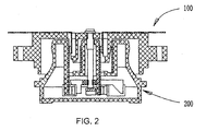
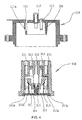
- Example one as shown in Figs 1,2, it includes a plug 100 and a socket 200 that are interconnectable and relatively ratable.
- a plughole In the center of the socket's upper face there is a plughole and a number of ring grooves being concentric with the plughole, inside the plughole is a center power supply receiving pillar 202, inside and outside the ring groove there are power supply contact sheets 201,203, inside the power supply contact's 201 underside there is a immovable contact 201a extended out words, and outside the power supply contact 203 there is a immovable contact 203a.
- the socket 200 there are three corresponding power supply contacts 301,302,303 all in the form of movable contact sheets, which correspond to the power supply contact sheet 201, the power supply receiving pillar 202 and the power supply contact sheet 203 respectively;
- the power supply contact sheet 302 is connected with the earth wire of the power supply and pressed against the power supply receiving pillar 202 all the time;
- the power supply contacts 301,303 are respectively connected with the live wire and the zero line of the power supply, and that, on the one side of the supply contact sheet 301 there is a movable contact 301a, opposite to a immovable contact 201a of the power supply contact 201; on the one side of power supply contact sheet 303 there is a movable contact 303a, opposite to an immovable contact 203a of the power supply contact sheet 203.
- the isolating pushrod 304 is in the horizontal direction, whose central section is connected with the root of socket's center receiving pillar(202), on the both sides of which there is a underside warp, with a slope side, and the half part of its underside touches with power supply contact sheet 301, 303's corresponding parallel slope; which forms the contact switching mechanism.
- ring bulgy wall 104 that can be plugged into socket's 200 ring groove, and in the center of which there is a receiving plug pillar 102, corresponding to socket's power supply pillar 202; on two sides of which there are two receiving contact sheets 101, 103, and in its underside there are contact 101a, 103a, corresponding to socket's power supply contact sheets 201, 203 respectively.
- plug 100 in the center of electrical pot's bottom and fix the socket 200 in the center of power supply socket the thus, plug 100 and the socket 200 are interconnectable integratively and the electrical pot is heated when the electrical pot is put on the power supply socket.
- the isolating pushrod 304 under the action of its two sides acts on two power supply contact sheets 301,303 at the same time, however, in practical application, it can act one of the power supply contact sheets only through one side, and another power supply contact is connected directly with its corresponding line of power supply.
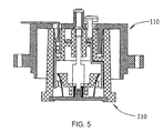
- Example 2 as shown in Figs. 4, 5, in the center of plug's 210 upper face there are one plughole and two ring grooves being concentric with the plughole, in the plughole there is a center power supply receiving pillar 212, outside the external ring groove there is a ring power supply contact sheet 211, at the bottom of the internal ring groove there is a ring power supply contact sheet 213, inside the power supply contact 211's underside there is a immovable contact 211a extended outwards, and outside of the power supply contact 213 there is a immovable contact 213a.
- the socket 200 there are three corresponding power supply contacts 311, 312, 313 all in the form of movable contact sheets, which correspond to the power supply contact sheet 211, the power supply receiving pillar 212 and the power supply contact sheet 213 respectively;
- the power supply contact sheet 312 is connected with the ground wire of the power supply and pressed against power supply receiving pillar 212 all the time;
- the power supply contacts 311, 313 are in the vertical direction, connected with live wire and zero line of power supply respectively, and that, on one side of the supply contact sheet 311 there is a movable contact 311a, opposite to the immovable contact 211a of the power supply contact 211; on one side of power supply contact sheet 313 there is a movable contact 313a, opposite to the immovable contact 213a of the power supply contact sheet 213.
- the insulating sheet whose section is of inverted T-type and whose underside is held by a reset spring 315 is under the power supply receiving pillar 212. On its both sides there are power supply contact sheets 311, 313. And the upside of the insulating sheet 314 is connected with the root of the socket's center receiving pillar 212.
- ring bulgy wall 114 that can be plugged into socket's 210 ring groove, and in the center of which there is a receiving plug pillar 112, corresponding to socket's power supply pillar 212; on both sides of which there are two receiving contact sheets 111, 113, corresponding to socket's power supply contact sheets 211, 213 respectively and there is contact 111a in the receiving contact sheet 111.
- the receiving contact sheet 111 of the plug touches the power supply contact sheets 211 of the socket through contact 111a
- the receiving plug pillar 113 touches the power supply contact sheet 213
- the plug's center plug pillar 112 presses the socket's center receiving pillar 212 down
- the isolating sheet 314 moves down with it, causing the vertical power supply contact sheets 311,313 to move towards power supply contact sheets 211, 213 respectively until movable contacts 311a, 313a respectively touch immovable contacts 211a, 213a.
- the isolating sheet 314 under the action of its both sides acts on two power supply contact sheets 311,313 at the same time, however, in practical application, it can act one of the power supply contact sheets only through one side, and another power supply contact is connected directly with its corresponding line of power supply.
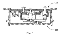
- Example 3 as shown in Figs 6, 7, in the center of the socket's 220 upper face there are one a plughole and two ring grooves being concentric with the plughole, inside the plughole is a center power supply receiving pillar 222, at the bottom of the ring groove there are ring power supply contact sheets 221, 223, with a underside extended outwords and a tortuous end where there are immovable contacts 221a, 223a.
- the socket 200 there are three corresponding power supply contacts sheets 321, 322, 323 all in be form of movable contact sheets, which correspond to the power supply contact sheet 221, the power supply receiving pillar 222 and power supply contact sheet 223; the power supply contact sheet 322 is connected with the ground wire of the power supply and pressed against the power supply receiving pillar 222 all the time; on the immovable contacts 221a, 223a the power supply contacts 321, 323 are connected with the live wire and the zero line of power supply respectively, and that on, the underside of supply contact sheets 321, 323 there are movable contacts 321a, 323a, corresponding to immovable contacts 221a, 223a respectively.
- the isolating pushrod 324 is in horizontal direction, whose central section is connected with the root of socket's center receiving pillar 222 and whose two sides are connected with the power supply contact sheets 321, 323 respectively.
- a ring bulgy wall 124 that can be pluged into the socket's 220 ring groove, and in the center of which there is a receiving plug pillar 122, corresponding to socket's power supply pillar 222; on both sides of which there are two receiving plug pillars 121, 123, corresponding to socket's power supply contact sheets 221, 223 respectively.
- the receiving plug pillar 121,123 of the plug touch the power supply contact sheets 221,223 of the socket respectively.
- the plug's center plug pillar 122 presses the socket's center receiving pillar 222 down, the isolating pushrod 324 then moves down with it, under the action of vertical power supply contact sheets 321, 323, which causes the vertical power supply contact sheets 321, 323 to move towards power supply immovable contacts 221a, 223a respectively until movable contacts 321a, 323a touch immovable contacts 221a, 223a respectively.
- the isolating pushrod 324 under the action of its both sides acts on two power supply contact sheets 321, 323 at the same time, however, in practical application, it can act one of the power supply contact sheets only through one side, and another power supply contact is connected directly with its corresponding line of power supply.
- Example 4 as shown in Figs 8, 9, 10 , in the center of the socket's 230 upper face there is a plughole and a ring grooves being concentric with the plughole, inside the plughole is a center power supply plug pillar 232, on the inside and the outside of the ring groove there are ring power supply contact sheets 231, 233, with an underside extended out words and a tortuous end where there are immovable contacts 231a, 233a.
- the socket 230 On the underside of the socket 230 there are three corresponding power supply contacts sheets 331, 332, 333 all in the form of movable contact sheets, which correspond to the power supply contact sheet 231, the power supply receiving pillar 232 and the power supply contact sheet 233 respectively; the power supply contact sheet 332 is connected with the ground wire of the power supply and pressed against the power supply receiving pillar 232 all the time; the power supply contacts 331, 333 which are in parallel and connected with the live wire and the zero line of power supply respectively, one side of which is fixed on the shell of the socket, on another side there are movable contacts 331a, 333a, which are under the immovable contacts 231a, 233a and opposite to them respectively.
- the isolating lever 334 is of inverted T-type, one side of the vertical rod of which is connected with the root of socket's center receiving pillar 232 and the horizontal rod of which is under the movable contacts 331a, 333a.
- a ring bulgy wall 134 that can be pluged into the socket's 230 ring groove, and in the center of which there is a receiving plug pillar 132, corresponding to socket's power supply pillar 232; on both sides of which there are two receiving plug pillars 131, 133, and on the underside of it there are contacts 131a, 133a, corresponding to socket's power supply contact sheets 231, 233 respectively.
- the isolating lever 334 under the action of its both sides acts on two power supply contact sheets 331, 333 at the same time, however, in practical application, it can act one of the power supply contact sheets only through one side, and another power supply contact is connected directly with its corresponding line of the power supply.
- Example 5 as shown in Figs 11, 12, 13, in the center of the socket's 240 upper face there are one plughole and one ring grooves being concentric with the plughole, inside the plughole is a center power supply plug pillar 242, on the inside and outside of the ring groove there are ring power supply contact sheets 241, 243, with an underside extended down words and a tortuous end where there are immovable contacts 241a, 243a.
- the socket 240 On the underside of the socket 240 there are three corresponding power supply contacts sheets 341, 342, 343 all in the form of movable contact sheets, which correspond to the power supply contact sheet 241, the power supply receiving pillar 242 and the power supply contact sheet 243 respectively; the power supply contact sheet 342 is connected with the ground wire of the power supply and pressed against the power supply receiving pillar 242 all the time; the power supply contacts 341, 343 which are in parallel are connected with the live wire and the zero line of the power supply respectively, one side of which is fixed on the shell of the socket, on another side there are movable contacts 341 a, 343a, which are under immovable contacts 241a, 243a and opposite to them respectively, and its central section is held by pivot.
- the insulating slippery sheet 344 is lambdoidal, see Fig. 13. Its upside runs thoroughly through the bottom of socket's concentric ring groove and it can slip up and down. On its two undersides there are power supply contacts 341, 343 near their fixed parts above respectively.
- a ring bulgy wall 144 that can be pluged into socket's 240 ring groove, and in the center of which there is a receiving plug pillar 142, conesponding to socket's power supply pillar 242; on two sides of which there are two receiving contact sheets 141, 143, and the underside of it there are contacts 141a, 143a, corresponding to socket's power supply contact sheets 241, 243 respectively.
- the receiving plug pillars 141, 143 of the plug through power supply contacts 141a, 143a of plug touch the power supply contact sheets 241, 243 of the socket respectively
- the plug's center plug pillar 142 touches with the center receiving pillar 242; at this time, the ring bulgy wall 144 of socket 140 inserts into the ring groove of the socket 240, the insulating sheet 344 slips down under the action of the ring groove wall's 144 end, pressing the bacilliform movable contact sheets 341, 343, raising the movable contact under the action of the lever until movable contacts 341a, 343a touch immovable contacts 241a, 243a respectively.
- the isolating slippery sheet 344 under the action of its both sides acts on two power supply contact sheets 341, 343 at the same time, however, in practical application, it can act one of the power supply contact sheets only through one side, and another power supply contact is connected directly with its corresponding line of the power supply.
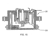
- Example 6 as shown in Figs 14, 15, in the center of the socket's 250 upper face there is a plughole and two ring grooves being concentric with the plughole, inside the plughole is a center power supply contact sheet 252, on the tortuous end underside extended outwards there is a immovable contact 252a; inside the external ring groove there is a power supply contact sheet 251, with an underside down words end; inside the internal ring groove there is a power supply contact sheet 253, and on the underside outstretched and tortuous end there is a immovable contact 253a.
- the socket 250 there are one immovable power supply contact sheet 351 and two power supply contact sheets 352, 353 in the movable contact sheet form, which correspond to power supply contact sheet 251, 252, 253 respectively;
- the power supply contact sheet 351 is connected with the underside outstreched end of the power supply contact sheet 251 all the time and the ground wire of the power supply;
- the power supply contacts 352, 353 is connected with the live wire and the zero line of electric line respectively, they are set in parallel with one above another, with respective movable contacts 352a, 353a set in their upsides, and opposite to immovable contacts 252a, 253a respectively.
- a ring bulgy wall 154 that can be pluged into the socket's 250 ring groove, and in the center of which there is a receiving plug pillar 152, corresponding to socket's power supply pillar 252; on both sides of which there is a V-type receiving contact sheet 151 and a receiving plug pillar 153, corresponding to socket's power supply contact sheets 251, 253 respectively.
- a cuneiform insulating sheet 354 holds the movable contact end of the power supply contacts 352, 353 on its slope, and its inside is held by a reset spring 355, forming an outward horizontal moving trend.
- the receiving contact sheet 151 and the receiving plug pillars 152, 153 of the plug touch power the supply contacts 251, 252, 253 of the socket respectively; at this moment, the cuneiform insulating sheet 354 under the action of plug's ring external wall 155 moves down in words laterally and pushes movable contacts 352, 353 on the slope upwards until movable contacts 352a, 353a touch immovable contacts 252a, 253a.
- the cuneiform insulating sheet 354 via its slope under the action of its two sides acts on both power supply contact sheets 352, 353 at the same time, however, in practical application, it can act one of the power supply contact sheets only through one side, and another power supply contact is connected directly with its corresponding line of the power supply.
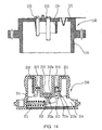
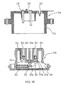
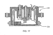
- Example 7 as shown in Figs. 16, 17, it's a variation of the example 6, with one figure different from above example 6, that is, all the grooves on the upper face of the sockets are concentric ring grooves (in this example there are three concentric ring grooves 251, 252, 253 on it), but not a center hole with a concentric ring groove. Its superiority is that it can overcome the restriction on the power and structure that is caused by the center plughole's limited size.
Landscapes
- Details Of Connecting Devices For Male And Female Coupling (AREA)
- Connector Housings Or Holding Contact Members (AREA)
Applications Claiming Priority (3)
| Application Number | Priority Date | Filing Date | Title |
|---|---|---|---|
| CN 02136488 CN1196236C (zh) | 2002-08-12 | 2002-08-12 | 一种用于无绳电器的电连接器 |
| CN02136488 | 2002-08-12 | ||
| PCT/CN2003/000601 WO2004015823A1 (fr) | 2002-08-12 | 2003-07-28 | Connecteur electrique pour appareil electrique sans fil |
Publications (3)
| Publication Number | Publication Date |
|---|---|
| EP1536528A1 true EP1536528A1 (de) | 2005-06-01 |
| EP1536528A4 EP1536528A4 (de) | 2007-04-18 |
| EP1536528B1 EP1536528B1 (de) | 2010-02-03 |
Family
ID=4748662
Family Applications (1)
| Application Number | Title | Priority Date | Filing Date |
|---|---|---|---|
| EP03783897A Expired - Lifetime EP1536528B1 (de) | 2002-08-12 | 2003-07-28 | Elektrischer verbinder für eine drahtlose elektrische vorrichtung |
Country Status (5)
| Country | Link |
|---|---|
| EP (1) | EP1536528B1 (de) |
| CN (1) | CN1196236C (de) |
| AU (1) | AU2003255085A1 (de) |
| DE (1) | DE60331193D1 (de) |
| WO (1) | WO2004015823A1 (de) |
Families Citing this family (13)
| Publication number | Priority date | Publication date | Assignee | Title |
|---|---|---|---|---|
| CN100452561C (zh) * | 2006-01-13 | 2009-01-14 | 柯赐龙 | 一种用于无绳电器的电源座 |
| CN101345368B (zh) * | 2008-08-12 | 2010-06-16 | 吴其如 | 无绳电连接器 |
| DE102010021772A1 (de) * | 2009-12-07 | 2011-06-09 | Msx Technology Ag | Anschlussanordnung zum Schließen eines elektrischen Kontakts |
| CN104124579B (zh) * | 2013-04-28 | 2017-12-26 | 海尔集团技术研发中心 | 无尾电器有线与无线供电模式兼容的插座及无尾电器 |
| CN106361144B (zh) * | 2013-09-03 | 2018-11-27 | 乐清市华尊电气有限公司 | 一种电水壶底座 |
| CN103986001A (zh) * | 2014-06-03 | 2014-08-13 | 常州汇森电子有限公司 | 杠杆式安全插座 |
| CN108462803A (zh) * | 2017-04-07 | 2018-08-28 | 佛山尘凡环保科技有限公司 | 一种信息传输设备 |
| CN107123879B (zh) * | 2017-06-21 | 2023-04-28 | 小熊电器股份有限公司 | 连接可靠的开关接头及锅具 |
| CN108011262A (zh) * | 2017-12-07 | 2018-05-08 | 王亦锋 | 一种安全通断电的家用电源装置 |
| CN110391567B (zh) * | 2018-04-18 | 2025-05-02 | 万沥 | 一种插座旋转单元结构 |
| CN109728481A (zh) * | 2018-12-18 | 2019-05-07 | 南京金城机械有限公司 | 一种电动车充电安全开关 |
| CN112736600B (zh) * | 2020-12-04 | 2022-06-28 | 中国特种飞行器研究所 | 一种快速拆装旋转连接器 |
| CN113550200A (zh) * | 2021-08-01 | 2021-10-26 | 宫成军 | 一种沥青混凝土搅拌装置 |
Family Cites Families (8)
| Publication number | Priority date | Publication date | Assignee | Title |
|---|---|---|---|---|
| DE2036268A1 (de) * | 1970-07-22 | 1972-01-27 | Harsanyi E | Schnurloses elektrisches Bugeleisen mit Untersatz |
| CN87209125U (zh) * | 1987-06-13 | 1988-06-22 | 许中一 | 新型防触电插头插座 |
| CN87213184U (zh) * | 1987-08-31 | 1988-09-14 | 许意雄 | 微动开关式通用安全插座 |
| NZ255483A (en) * | 1992-09-02 | 1997-04-24 | Otter Controls Ltd | Shuttered plug/socket connector for cordless kettle allows engagement in any rotational alignment |
| CN2175473Y (zh) * | 1993-10-26 | 1994-08-24 | 钟乾麟 | 安全插座 |
| GB2307362B (en) * | 1996-10-29 | 1997-10-08 | Dualit Ltd | Cordless electric kettle |
| CN2371698Y (zh) * | 1998-11-05 | 2000-03-29 | 邵志成 | 旋转电器连接器 |
| CN2422757Y (zh) * | 2000-04-30 | 2001-03-07 | 杨宁恩 | 电气连接器 |
-
2002
- 2002-08-12 CN CN 02136488 patent/CN1196236C/zh not_active Expired - Fee Related
-
2003
- 2003-07-28 EP EP03783897A patent/EP1536528B1/de not_active Expired - Lifetime
- 2003-07-28 WO PCT/CN2003/000601 patent/WO2004015823A1/zh not_active Ceased
- 2003-07-28 AU AU2003255085A patent/AU2003255085A1/en not_active Abandoned
- 2003-07-28 DE DE60331193T patent/DE60331193D1/de not_active Expired - Lifetime
Also Published As
| Publication number | Publication date |
|---|---|
| CN1196236C (zh) | 2005-04-06 |
| AU2003255085A1 (en) | 2004-02-25 |
| CN1396683A (zh) | 2003-02-12 |
| EP1536528B1 (de) | 2010-02-03 |
| EP1536528A4 (de) | 2007-04-18 |
| DE60331193D1 (de) | 2010-03-25 |
| WO2004015823A1 (fr) | 2004-02-19 |
Similar Documents
| Publication | Publication Date | Title |
|---|---|---|
| CN2556818Y (zh) | 电连接器 | |
| EP1536528B1 (de) | Elektrischer verbinder für eine drahtlose elektrische vorrichtung | |
| US6302717B1 (en) | Multiple socket electric adapter | |
| CN203707514U (zh) | 一种多功能插座 | |
| US20080261420A1 (en) | Safety electric plug for preventing electric shock | |
| DE3879496D1 (de) | Vielpolige steckvorrichtung. | |
| US3299390A (en) | Electrical connector with grounding terminal | |
| GB2442426B (en) | A universal power socket | |
| CN101521346B (zh) | 无绳电器的安全耦合器 | |
| CN103178378B (zh) | 接电单元及其插座 | |
| WO2003001952A3 (de) | Küchengefäss mit einem heizboden | |
| CN101308969B (zh) | 用于无绳电热水器的供电底座内的插座连接器及电热水器 | |
| GB2410844A (en) | Swivel electrical connector | |
| CN201327926Y (zh) | 用于无绳电器的耦合器 | |
| KR19980052843U (ko) | 분리 가능한 멀티 콘센트 | |
| CN202695835U (zh) | 防水电连接器和食物加工机 | |
| KR20050106726A (ko) | 콘센트 | |
| CN2870225Y (zh) | 无绳电器的安全电源座 | |
| GB2361103A (en) | Illuminated push-button switch | |
| JP2003086285A (ja) | 電源プラグ | |
| KR200270384Y1 (ko) | 플러그 일체형 다중콘센트 | |
| RU143380U1 (ru) | Основание беспроводного электроприбора и беспроводной электроприбор | |
| US20020094712A1 (en) | Electrical connector and mating fitting | |
| CN104577556A (zh) | 一种带开关保护的插座 | |
| CN204424640U (zh) | 一种移动插座组件 |
Legal Events
| Date | Code | Title | Description |
|---|---|---|---|
| PUAI | Public reference made under article 153(3) epc to a published international application that has entered the european phase |
Free format text: ORIGINAL CODE: 0009012 |
|
| 17P | Request for examination filed |
Effective date: 20050309 |
|
| AK | Designated contracting states |
Kind code of ref document: A1 Designated state(s): AT BE BG CH CY CZ DE DK EE ES FI FR GB GR HU IE IT LI LU MC NL PT RO SE SI SK TR |
|
| AX | Request for extension of the european patent |
Extension state: AL LT LV MK |
|
| DAX | Request for extension of the european patent (deleted) | ||
| RBV | Designated contracting states (corrected) |
Designated state(s): DE GB |
|
| A4 | Supplementary search report drawn up and despatched |
Effective date: 20070316 |
|
| 17Q | First examination report despatched |
Effective date: 20080523 |
|
| GRAP | Despatch of communication of intention to grant a patent |
Free format text: ORIGINAL CODE: EPIDOSNIGR1 |
|
| GRAS | Grant fee paid |
Free format text: ORIGINAL CODE: EPIDOSNIGR3 |
|
| GRAA | (expected) grant |
Free format text: ORIGINAL CODE: 0009210 |
|
| AK | Designated contracting states |
Kind code of ref document: B1 Designated state(s): DE GB |
|
| REG | Reference to a national code |
Ref country code: GB Ref legal event code: FG4D |
|
| REF | Corresponds to: |
Ref document number: 60331193 Country of ref document: DE Date of ref document: 20100325 Kind code of ref document: P |
|
| PLBE | No opposition filed within time limit |
Free format text: ORIGINAL CODE: 0009261 |
|
| STAA | Information on the status of an ep patent application or granted ep patent |
Free format text: STATUS: NO OPPOSITION FILED WITHIN TIME LIMIT |
|
| 26N | No opposition filed |
Effective date: 20101104 |
|
| PGFP | Annual fee paid to national office [announced via postgrant information from national office to epo] |
Ref country code: GB Payment date: 20120627 Year of fee payment: 10 |
|
| PGFP | Annual fee paid to national office [announced via postgrant information from national office to epo] |
Ref country code: DE Payment date: 20120919 Year of fee payment: 10 |
|
| GBPC | Gb: european patent ceased through non-payment of renewal fee |
Effective date: 20130728 |
|
| PG25 | Lapsed in a contracting state [announced via postgrant information from national office to epo] |
Ref country code: GB Free format text: LAPSE BECAUSE OF NON-PAYMENT OF DUE FEES Effective date: 20130728 Ref country code: DE Free format text: LAPSE BECAUSE OF NON-PAYMENT OF DUE FEES Effective date: 20140201 |
|
| REG | Reference to a national code |
Ref country code: DE Ref legal event code: R119 Ref document number: 60331193 Country of ref document: DE Effective date: 20140201 |