EP1536518A1 - Crimp contact which can easily be reduced in size - Google Patents
Crimp contact which can easily be reduced in size Download PDFInfo
- Publication number
- EP1536518A1 EP1536518A1 EP04028034A EP04028034A EP1536518A1 EP 1536518 A1 EP1536518 A1 EP 1536518A1 EP 04028034 A EP04028034 A EP 04028034A EP 04028034 A EP04028034 A EP 04028034A EP 1536518 A1 EP1536518 A1 EP 1536518A1
- Authority
- EP
- European Patent Office
- Prior art keywords
- core wire
- cladding
- crimping
- crimp contact
- crimping portion
- Prior art date
- Legal status (The legal status is an assumption and is not a legal conclusion. Google has not performed a legal analysis and makes no representation as to the accuracy of the status listed.)
- Granted
Links
Images

Classifications
-
- H—ELECTRICITY
- H01—ELECTRIC ELEMENTS
- H01R—ELECTRICALLY-CONDUCTIVE CONNECTIONS; STRUCTURAL ASSOCIATIONS OF A PLURALITY OF MUTUALLY-INSULATED ELECTRICAL CONNECTING ELEMENTS; COUPLING DEVICES; CURRENT COLLECTORS
- H01R4/00—Electrically-conductive connections between two or more conductive members in direct contact, i.e. touching one another; Means for effecting or maintaining such contact; Electrically-conductive connections having two or more spaced connecting locations for conductors and using contact members penetrating insulation
- H01R4/10—Electrically-conductive connections between two or more conductive members in direct contact, i.e. touching one another; Means for effecting or maintaining such contact; Electrically-conductive connections having two or more spaced connecting locations for conductors and using contact members penetrating insulation effected solely by twisting, wrapping, bending, crimping, or other permanent deformation
- H01R4/18—Electrically-conductive connections between two or more conductive members in direct contact, i.e. touching one another; Means for effecting or maintaining such contact; Electrically-conductive connections having two or more spaced connecting locations for conductors and using contact members penetrating insulation effected solely by twisting, wrapping, bending, crimping, or other permanent deformation by crimping
- H01R4/183—Electrically-conductive connections between two or more conductive members in direct contact, i.e. touching one another; Means for effecting or maintaining such contact; Electrically-conductive connections having two or more spaced connecting locations for conductors and using contact members penetrating insulation effected solely by twisting, wrapping, bending, crimping, or other permanent deformation by crimping for cylindrical elongated bodies, e.g. cables having circular cross-section
- H01R4/184—Electrically-conductive connections between two or more conductive members in direct contact, i.e. touching one another; Means for effecting or maintaining such contact; Electrically-conductive connections having two or more spaced connecting locations for conductors and using contact members penetrating insulation effected solely by twisting, wrapping, bending, crimping, or other permanent deformation by crimping for cylindrical elongated bodies, e.g. cables having circular cross-section comprising a U-shaped wire-receiving portion
- H01R4/185—Electrically-conductive connections between two or more conductive members in direct contact, i.e. touching one another; Means for effecting or maintaining such contact; Electrically-conductive connections having two or more spaced connecting locations for conductors and using contact members penetrating insulation effected solely by twisting, wrapping, bending, crimping, or other permanent deformation by crimping for cylindrical elongated bodies, e.g. cables having circular cross-section comprising a U-shaped wire-receiving portion combined with a U-shaped insulation-receiving portion
Definitions
- This invention relates to a crimp contact to be connected to a core wire of a cable by crimping.
- a conventional crimp contact has a core wire crimping portion for crimping a core wire of a cable and a cladding crimping portion for crimping a cladding portion covering the core wire of the cable (for example, see Japanese Patent Application Publication (JP-A) No. H5-343109).
- Another conventional crimp contact comprises a core wire crimping portion and a cladding crimping portion each of which has a pair of metal members opposite to each other and which is different in height from the core wire crimping portion (for example, see Japanese Patent Application Publication (JP-A) No. H11-297375).
- the core wire is subjected to a bending stress in an area between crimped portions crimped by the core wire crimping portion and the cladding crimping portion, respectively.
- the distance between the core wire crimping portion and the cladding crimping portion is increased, a whole of the crimp contact can not be reduced in size.
- the core wire of the cable is wound around the crimp contact.
- an operation of winding the core wire is complicated and is therefore difficult to automate, resulting in low productivity.
- a special crimping tool is required which is provided with an escape portion for the core wire wound around the crimp contact.
- a crimp contact to be connected to a cable having a conductive core wire and an insulating cladding portion covering the core wire
- the crimp contact comprising a cladding crimping portion for crimping the cladding portion and a core wire crimping portion arranged adjacent to the cladding crimping portion for crimping the core wire
- the core wire crimping portion comprising a base portion for receiving the core wire and a first core wire barrel extending from the base portion for crimping the core wire to cover an outside of the core wire, the first core wire barrel having a relatively longer length from the base portion at a part relatively far from the cladding crimping portion and a relatively shorter length from the base portion at another part relatively near to the cladding crimping portion.
- a crimp contact according to an embodiment of the present invention will be described.
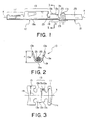
- the crimp contact 10 illustrated in the figure has a cladding crimping portion 11, a core wire crimping portion 13 adjacent to one side of the cladding crimping portion 11, a holding portion 15 adjacent to one side of the core wire crimping portion 13, and a contacting portion 17 adjacent to one side of the holding portion 15.
- the cladding crimping portion 11, the core wire crimping portion 13, the holding portion 15, and the contacting portion 17 are arranged at predetermined intervals from one another in a predetermined direction parallel to one axis X and are connected to one another by a common base 19.
- the cladding crimping portion 11 is a portion for holding an insulating cladding portion 25 covering a conductive core wire 23 of a cable 21.
- the core wire crimping portion 13 is a portion for collectively holding the core wire 23 comprising a plurality of lead wires exposed from one end of the cladding portion 25 of the cable 21 and extending in the predetermined direction.
- the holding portion 15 is a portion to be inserted into and held by a receiving portion of an insulator (not shown).
- the contacting portion 17 is a portion extending from one end of the core wire crimping portion 13 in the predetermined direction to be contacted with a mating contact (not shown).
- the cladding crimping portion 13 has a pair of cladding barrels 11a extending from opposite sides of the base portion 19, which are parallel to the predetermined direction, and faced to each other with a space left therebetween.
- the cladding barrels 11a are bent inward around the cladding portion 25 of the cable 21 placed on the base portion 19 so as to cover the cladding portion 25.
- the core wire crimping portion 13 has a pair of core wire barrels 13a extending from the opposite sides of the base portion 19, which are parallel to the predetermined direction, and faced to each other with a space left therebetween.
- the core wire barrels 13a form a first core wire barrel and a second core wire barrel, respectively.
- FIG. 3 shows the cladding crimping portion 11 and the core wire crimping portion 13 of the crimp contact 10 in a developed shape.
- a thin conductive metal plate is punched to obtain the crimp contact 10 in a developed shape. Thereafter, a predetermined bending process is carried out to form the crimp contact 10. Specifically, after the developed shape in Fig. 3 is obtained, the cladding crimping portion 11 and the core wire crimping portion 13 are formed by the bending process so that the cladding barrels 11a are faced to each other and that the core wire barrels 13a are faced to each other.
- the core wire crimping portion 13 has the core wire barrels 13a extending from the opposite sides of the base portion 19 and faced to each other with a space left therebetween. As best shown in a sectional view in Fig. 2, the core wire crimping portion 13 exhibits a generally U-shaped section formed by the core wire barrels 13a and the base portion 19. Although not shown in the figure, the cladding crimping portion 11 exhibits a generally U-shaped section formed by the cladding barrels 11a and the base portion 19.
- the core wire crimping portion 13 has a special shape in which a height H (see Fig. 2) from a base surface 19a of the base portion 19 to an extending end 13b of each core wire barrel 13a is changed stepwise at an intermediate point in the predetermined direction.
- each core wire barrel 13a has a step portion 13c between a first part and a second part where the extending end 13b is high and low, respectively.
- the first part is relatively far from the cladding crimping portion 11 than the intermediate point in the predetermined direction.
- the second part is relatively near to the cladding crimping portion 11 than the intermediate point in the predetermined direction.
- the first part of each core wire barrel 13a has a shorter length from the base portion 19 than that of the second part.
- the cladding portion 25 at an end portion of the cable 21 is removed to expose the core wire 23.
- the cable 21 is put on the base portion 19.
- the core wire 23 and the cladding portion 25 are positioned at the core wire crimping portion 13 and the cladding crimping portion 11, respectively.
- the core wire barrels 13a and the cladding barrels 11a are bent inward so as to cover the core wire 23 and the cladding portion 25 from the outside, respectively.
- the core wire 23 and the cladding portion 25 are held by the core wire crimping portion 13 and the cladding crimping portion 11 by crimping, respectively.
- the extending ends 13b of the core wire barrels 3a become in contact with to each other at a center of the base portion 19 in a direction perpendicular to the predetermined direction.
- the core wire barrels 13a are inwardly bent from opposite sides of the core wire 23 to be uniformly rolled inside.
- the extending ends 13b of the core wire barrels 13a are curled towards the center of the core wire 23 to collapse a whole of the core wire 23 in a vertical direction and to clamp the core wire 23.
- a known bending/crimping tool such as a crimper or an anvil known in the art, for bending the core wire barrels 13a.
- the core wire barrels 13a By providing the core wire barrels 13a with the step portions 13c, it is possible to delay bending of the second part, i.e., the part nearer to the cladding crimping portion 11 than the step portion 13c at an early stage of crimping. Therefore, it is possible to slowly clamp the core wire 23 at a specific part having a length L1 in Fig. 4. As a consequence, a damage upon the core wire 23 by crimping is reduced to thereby minimize a loss of a tensile strength of the cable 21 and maintain a sufficient tensile strength. Further, the bending stress of the core wire 23 between the crimped portions crimped by the core wire crimping portion 13 and the cladding portion crimping portion 11 is reduced.
- the distance between the core wire crimping portion 13 and the cladding crimping portion 11 can be decreased so that a whole of the crimp contact 10 can be reduced in size.
- the crimping operation need not be modified. Therefore, the crimping operation can be carried out by the use of an existing facility and an existing crimping tool.
- each of the core wire barrels 13a has an inclined portion 13d formed at a part of the extending end 13b.
- the inclined portion 13d is formed on the extending end 13b at a part relatively near to the cladding crimping portion 11 than the intermediate point of the core wire barrel 13a in the predetermined direction, i.e., at the second part.
- the height H (see Fig. 2) from the base surface 19a of the base portion 19 to the extending end 13b of the core wire barrel 13a is gradually lowered from the intermediate point of the extending end 13b of the core wire barrel 13a in the predetermined direction towards the cladding crimping portion 11.
- the length of the second part from the base portion 19 is gradually shortened towards the cladding crimping portion 11.
- the core wire barrel 13a is provided with the inclined portion 13d.
- the above-mentioned crimp contact may be used as a component of a cable connector for connecting electronic apparatuses to each other or module units such as disk units to each other.
- the core wire crimping portion comprising two core wire barrels
- the core wire crimping portion may comprise only a single core wire barrel.
Landscapes
- Connections Effected By Soldering, Adhesion, Or Permanent Deformation (AREA)
Abstract
Description
Claims (10)
- A crimp contact to be connected to a cable having a conductive core wire and an insulating cladding portion covering the core wire, the crimp contact comprising:a cladding crimping portion for crimping the cladding portion; anda core wire crimping portion arranged adjacent to the cladding crimping portion for crimping the core wire,the core wire crimping portion comprising:a base portion for receiving the core wire; anda first core wire barrel extending from the base portion for crimping the core wire to cover an outside of the core wire, the first core wire barrel having a relatively longer length from the base portion at a part relatively far from the cladding crimping portion and a relatively shorter length from the base portion at another part relatively near to the cladding crimping portion.
- The crimp contact according to claim 1, wherein the first core wire barrel has a first part relatively far from the cladding crimping portion and a second part relatively near to the cladding crimping portion, the second part is shorter in length from the base portion than the first part.
- The crimp contact according to claim 2, wherein the first core wire barrel has an extending end, the extending end having a step portion between the first and the second parts, or
wherein the first core wire barrel has an extending end, the extending end having an inclined portion formed at the second part so that the length from the base portion to the extending end is shorter away from the first part. - The crimp contact according to any of claims 1 to 3, wherein the core wire crimping portion further has a second core wire barrel extending from the base portion and cooperated with the first core wire barrel for crimping the core wire to cover the outside of the core wire.
- The crimp contact according to claim 4, wherein the second core wire barrel has a relatively longer length from the base portion at a part relatively far from the cladding crimping portion and a relatively shorter length from the base portion at another part relatively near to the cladding crimping portion.
- The crimp contact according to claim 4, wherein the second core wire barrel has a first part relatively far from the cladding crimping portion and a second part relatively near to the cladding crimping portion, the second part is shorter in length from the base portion than the first part.
- The crimp contact according to claim 6, wherein the second core wire barrel has an extending end, the extending end having a step portion between the first and the second parts, or
wherein the second core wire barrel has an extending end, the extending end having an inclined portion formed at the second part so that the length from the base portion to the extending end is shorter away from the first part. - The crimp contact according to claim 4, wherein the first and the second core wire barrels are connected to opposite sides of the base portion, respectively, and faced to each other with a space left therebetween.
- The crimp contact according to claim 8, wherein the first and the second core wire barrels are symmetrical with each other with respect to a plane between the first and the second core wire barrels.
- The crimp contact according to any of claims 1 to 9, wherein the cladding crimping portion has a pair of cladding barrels covering the cladding portion from the outside.
Applications Claiming Priority (2)
| Application Number | Priority Date | Filing Date | Title |
|---|---|---|---|
| JP2003395678 | 2003-11-26 | ||
| JP2003395678A JP2005158497A (en) | 2003-11-26 | 2003-11-26 | Crimp contact |
Publications (2)
| Publication Number | Publication Date |
|---|---|
| EP1536518A1 true EP1536518A1 (en) | 2005-06-01 |
| EP1536518B1 EP1536518B1 (en) | 2009-01-14 |
Family
ID=34463800
Family Applications (1)
| Application Number | Title | Priority Date | Filing Date |
|---|---|---|---|
| EP04028034A Expired - Lifetime EP1536518B1 (en) | 2003-11-26 | 2004-11-25 | Crimp contact |
Country Status (5)
| Country | Link |
|---|---|
| US (1) | US7008274B2 (en) |
| EP (1) | EP1536518B1 (en) |
| JP (1) | JP2005158497A (en) |
| CN (1) | CN100337368C (en) |
| DE (1) | DE602004019036D1 (en) |
Cited By (5)
| Publication number | Priority date | Publication date | Assignee | Title |
|---|---|---|---|---|
| CN105281084A (en) * | 2014-07-23 | 2016-01-27 | 罗伯特·博世有限公司 | Crimp contact member |
| USD749524S1 (en) * | 2013-12-12 | 2016-02-16 | Japan Aviation Electronics Industry, Limited | Gripping surface for crimping terminal part |
| USD749523S1 (en) * | 2013-12-12 | 2016-02-16 | Japan Aviation Electronics Industry, Limited | Gripping surface for crimping terminal part |
| USD751510S1 (en) * | 2013-12-12 | 2016-03-15 | Japan Aviation Electronics Industry, Limited | Gripping surface for crimping terminal part |
| US20220131282A1 (en) * | 2020-10-26 | 2022-04-28 | Aptiv Technologies Limited | Electrical crimp terminal |
Families Citing this family (10)
| Publication number | Priority date | Publication date | Assignee | Title |
|---|---|---|---|---|
| JP5107693B2 (en) * | 2007-12-21 | 2012-12-26 | タイコエレクトロニクスジャパン合同会社 | Crimping structure and crimping method |
| JP5065125B2 (en) * | 2008-03-31 | 2012-10-31 | 古河電気工業株式会社 | Crimp terminal |
| JP2010040455A (en) * | 2008-08-07 | 2010-02-18 | Sumitomo Wiring Syst Ltd | Terminal metal fitting and wire harness |
| JP5629430B2 (en) * | 2008-12-09 | 2014-11-19 | 矢崎総業株式会社 | Terminal crimping structure to aluminum wire |
| JP5374208B2 (en) * | 2009-03-27 | 2013-12-25 | 矢崎総業株式会社 | Crimp terminal fitting |
| JP5674120B2 (en) * | 2010-12-13 | 2015-02-25 | 矢崎総業株式会社 | Wire connection structure of connector terminal and manufacturing method thereof |
| JP5601259B2 (en) * | 2011-03-24 | 2014-10-08 | 住友電装株式会社 | Terminal fitting |
| JP6701524B2 (en) * | 2016-11-11 | 2020-05-27 | 株式会社オートネットワーク技術研究所 | Electric wire mounting member, electric wire mounting member with electric wire, and connector |
| US12095214B2 (en) * | 2020-12-11 | 2024-09-17 | Yazaki Corporation | Connector and terminal fitting |
| CN115764351A (en) * | 2021-09-03 | 2023-03-07 | 泰科电子(上海)有限公司 | Connecting terminal and connecting assembly |
Citations (5)
| Publication number | Priority date | Publication date | Assignee | Title |
|---|---|---|---|---|
| GB907317A (en) * | 1960-03-22 | 1962-10-03 | Kent Mfg Corp | Wire-gripping sleeve of an electric terminal member |
| US4812138A (en) * | 1987-02-12 | 1989-03-14 | Yazaki Corporation | Connector terminal |
| JPH11297375A (en) * | 1998-04-15 | 1999-10-29 | Yazaki Corp | Crimp terminal |
| EP1020955A1 (en) * | 1999-01-15 | 2000-07-19 | RADIALL Société anonyme dite: | Coaxial connector element to be mounted to a coaxial cable end |
| EP1154520A1 (en) * | 2000-05-08 | 2001-11-14 | Tyco Electronics AMP K.K. | Electrical contact and method for press-bonding electrical contact to electrical wire |
Family Cites Families (9)
| Publication number | Priority date | Publication date | Assignee | Title |
|---|---|---|---|---|
| US2483424A (en) * | 1947-03-31 | 1949-10-04 | Electric Terminal Corp | Method of soldering terminals for electrical conductors |
| US2747171A (en) * | 1952-05-06 | 1956-05-22 | Crimpweld Corp | Means for connecting a member to an electrical wire |
| US3115244A (en) * | 1960-12-29 | 1963-12-24 | Gen Electric | Wire connector assembly |
| US3248686A (en) * | 1965-03-16 | 1966-04-26 | Elco Corp | Contact with locking feature |
| US3953103A (en) * | 1975-01-27 | 1976-04-27 | Western Electric Company, Inc. | Plug-in terminal |
| JPH05343109A (en) | 1992-06-08 | 1993-12-24 | Fujitsu Ltd | Connector terminal structure |
| US6000976A (en) * | 1993-11-30 | 1999-12-14 | Yazaki Corporation | Terminal for passing through waterproof rubber plug and method of producing terminal |
| US5567187A (en) * | 1994-06-16 | 1996-10-22 | Belden Wire & Cable Company | Reverse insulation grip blade |
| JP4037955B2 (en) | 1998-04-08 | 2008-01-23 | 東海カーボン株式会社 | Method for producing polymer electrolyte fuel cell separator member |
-
2003
- 2003-11-26 JP JP2003395678A patent/JP2005158497A/en active Pending
-
2004
- 2004-11-22 US US10/994,945 patent/US7008274B2/en not_active Expired - Fee Related
- 2004-11-23 CN CNB2004100950975A patent/CN100337368C/en not_active Expired - Fee Related
- 2004-11-25 DE DE602004019036T patent/DE602004019036D1/en not_active Expired - Lifetime
- 2004-11-25 EP EP04028034A patent/EP1536518B1/en not_active Expired - Lifetime
Patent Citations (5)
| Publication number | Priority date | Publication date | Assignee | Title |
|---|---|---|---|---|
| GB907317A (en) * | 1960-03-22 | 1962-10-03 | Kent Mfg Corp | Wire-gripping sleeve of an electric terminal member |
| US4812138A (en) * | 1987-02-12 | 1989-03-14 | Yazaki Corporation | Connector terminal |
| JPH11297375A (en) * | 1998-04-15 | 1999-10-29 | Yazaki Corp | Crimp terminal |
| EP1020955A1 (en) * | 1999-01-15 | 2000-07-19 | RADIALL Société anonyme dite: | Coaxial connector element to be mounted to a coaxial cable end |
| EP1154520A1 (en) * | 2000-05-08 | 2001-11-14 | Tyco Electronics AMP K.K. | Electrical contact and method for press-bonding electrical contact to electrical wire |
Non-Patent Citations (1)
| Title |
|---|
| PATENT ABSTRACTS OF JAPAN vol. 2000, no. 01 31 January 2000 (2000-01-31) * |
Cited By (7)
| Publication number | Priority date | Publication date | Assignee | Title |
|---|---|---|---|---|
| USD749524S1 (en) * | 2013-12-12 | 2016-02-16 | Japan Aviation Electronics Industry, Limited | Gripping surface for crimping terminal part |
| USD749523S1 (en) * | 2013-12-12 | 2016-02-16 | Japan Aviation Electronics Industry, Limited | Gripping surface for crimping terminal part |
| USD751510S1 (en) * | 2013-12-12 | 2016-03-15 | Japan Aviation Electronics Industry, Limited | Gripping surface for crimping terminal part |
| CN105281084A (en) * | 2014-07-23 | 2016-01-27 | 罗伯特·博世有限公司 | Crimp contact member |
| DE102014214384A1 (en) | 2014-07-23 | 2016-01-28 | Robert Bosch Gmbh | Crimpkontaktelement |
| US20220131282A1 (en) * | 2020-10-26 | 2022-04-28 | Aptiv Technologies Limited | Electrical crimp terminal |
| US11641068B2 (en) * | 2020-10-26 | 2023-05-02 | Aptiv Technologies Limited | Electrical crimp terminal for electrical wire |
Also Published As
| Publication number | Publication date |
|---|---|
| EP1536518B1 (en) | 2009-01-14 |
| CN100337368C (en) | 2007-09-12 |
| CN1622394A (en) | 2005-06-01 |
| JP2005158497A (en) | 2005-06-16 |
| DE602004019036D1 (en) | 2009-03-05 |
| US7008274B2 (en) | 2006-03-07 |
| US20050112961A1 (en) | 2005-05-26 |
Similar Documents
| Publication | Publication Date | Title |
|---|---|---|
| US7008274B2 (en) | Crimp contact which can easily be reduced in size | |
| CN103004038B (en) | Dies and crimping method | |
| US7775842B2 (en) | Crimping structure and crimping method | |
| US5561267A (en) | Crimp terminal and process for producing the same | |
| JP2812128B2 (en) | Terminal crimping device | |
| JP5169502B2 (en) | Splice connection wire and method of manufacturing splice connection wire | |
| US20200194907A1 (en) | Wire connection structure and harness manufacturing method | |
| EP0823756B1 (en) | Terminal fitting and manufacturing method thereof | |
| US20190199048A1 (en) | Multicore cable manufacturing apparatus and multicore cable manufacturing method | |
| US6193138B1 (en) | Pressure welding device and method for terminals | |
| JP4250103B2 (en) | Crimping device | |
| CN100394514C (en) | flat cable | |
| JP6786312B2 (en) | Crimping terminal | |
| US10707586B2 (en) | Wire with terminal | |
| JPH088034A (en) | Assembly method of flat cable connector | |
| JP7265132B2 (en) | Cable connector and in-vehicle camera module connector equipped with it | |
| JP3378751B2 (en) | Connecting terminal | |
| JP2019212570A (en) | Terminal crimping device and terminal crimping method | |
| JP3418513B2 (en) | Connecting terminal | |
| JPH088033A (en) | Assembly method of flat cable connector | |
| JPH0553133U (en) | Joint terminal | |
| US11677167B2 (en) | Electric wire with terminal and terminal crimping device | |
| JPH0817546A (en) | Assembly method of flat cable connector | |
| JP6582089B2 (en) | Crimp connection structure, terminal crimping device, and terminal crimping tooth mold | |
| JP2025147472A (en) | Crimping type, manufacturing method of electric wire with terminal, and electric wire with terminal |
Legal Events
| Date | Code | Title | Description |
|---|---|---|---|
| PUAI | Public reference made under article 153(3) epc to a published international application that has entered the european phase |
Free format text: ORIGINAL CODE: 0009012 |
|
| AK | Designated contracting states |
Kind code of ref document: A1 Designated state(s): AT BE BG CH CY CZ DE DK EE ES FI FR GB GR HU IE IS IT LI LU MC NL PL PT RO SE SI SK TR |
|
| AX | Request for extension of the european patent |
Extension state: AL HR LT LV MK YU |
|
| 17P | Request for examination filed |
Effective date: 20051128 |
|
| AKX | Designation fees paid |
Designated state(s): DE FR GB SE |
|
| 17Q | First examination report despatched |
Effective date: 20060130 |
|
| GRAP | Despatch of communication of intention to grant a patent |
Free format text: ORIGINAL CODE: EPIDOSNIGR1 |
|
| RTI1 | Title (correction) |
Free format text: CRIMP CONTACT |
|
| GRAS | Grant fee paid |
Free format text: ORIGINAL CODE: EPIDOSNIGR3 |
|
| GRAA | (expected) grant |
Free format text: ORIGINAL CODE: 0009210 |
|
| AK | Designated contracting states |
Kind code of ref document: B1 Designated state(s): DE FR GB SE |
|
| REG | Reference to a national code |
Ref country code: GB Ref legal event code: FG4D |
|
| REF | Corresponds to: |
Ref document number: 602004019036 Country of ref document: DE Date of ref document: 20090305 Kind code of ref document: P |
|
| REG | Reference to a national code |
Ref country code: SE Ref legal event code: TRGR |
|
| PLBE | No opposition filed within time limit |
Free format text: ORIGINAL CODE: 0009261 |
|
| STAA | Information on the status of an ep patent application or granted ep patent |
Free format text: STATUS: NO OPPOSITION FILED WITHIN TIME LIMIT |
|
| 26N | No opposition filed |
Effective date: 20091015 |
|
| PGFP | Annual fee paid to national office [announced via postgrant information from national office to epo] |
Ref country code: GB Payment date: 20141119 Year of fee payment: 11 Ref country code: DE Payment date: 20141118 Year of fee payment: 11 |
|
| REG | Reference to a national code |
Ref country code: FR Ref legal event code: PLFP Year of fee payment: 12 |
|
| PGFP | Annual fee paid to national office [announced via postgrant information from national office to epo] |
Ref country code: SE Payment date: 20151111 Year of fee payment: 12 Ref country code: FR Payment date: 20151008 Year of fee payment: 12 |
|
| REG | Reference to a national code |
Ref country code: DE Ref legal event code: R119 Ref document number: 602004019036 Country of ref document: DE |
|
| GBPC | Gb: european patent ceased through non-payment of renewal fee |
Effective date: 20151125 |
|
| PG25 | Lapsed in a contracting state [announced via postgrant information from national office to epo] |
Ref country code: GB Free format text: LAPSE BECAUSE OF NON-PAYMENT OF DUE FEES Effective date: 20151125 Ref country code: DE Free format text: LAPSE BECAUSE OF NON-PAYMENT OF DUE FEES Effective date: 20160601 |
|
| REG | Reference to a national code |
Ref country code: SE Ref legal event code: EUG |
|
| REG | Reference to a national code |
Ref country code: FR Ref legal event code: ST Effective date: 20170731 |
|
| PG25 | Lapsed in a contracting state [announced via postgrant information from national office to epo] |
Ref country code: SE Free format text: LAPSE BECAUSE OF NON-PAYMENT OF DUE FEES Effective date: 20161126 |
|
| PG25 | Lapsed in a contracting state [announced via postgrant information from national office to epo] |
Ref country code: FR Free format text: LAPSE BECAUSE OF NON-PAYMENT OF DUE FEES Effective date: 20161130 |