EP1536217B1 - Device for detecting absolute rotation angle and torque - Google Patents
Device for detecting absolute rotation angle and torque Download PDFInfo
- Publication number
- EP1536217B1 EP1536217B1 EP04772859A EP04772859A EP1536217B1 EP 1536217 B1 EP1536217 B1 EP 1536217B1 EP 04772859 A EP04772859 A EP 04772859A EP 04772859 A EP04772859 A EP 04772859A EP 1536217 B1 EP1536217 B1 EP 1536217B1
- Authority
- EP
- European Patent Office
- Prior art keywords
- gear
- absolute rotation
- rotation angle
- torque
- cpu
- Prior art date
- Legal status (The legal status is an assumption and is not a legal conclusion. Google has not performed a legal analysis and makes no representation as to the accuracy of the status listed.)
- Expired - Lifetime
Links
Images

Classifications
-
- B—PERFORMING OPERATIONS; TRANSPORTING
- B62—LAND VEHICLES FOR TRAVELLING OTHERWISE THAN ON RAILS
- B62D—MOTOR VEHICLES; TRAILERS
- B62D6/00—Arrangements for automatically controlling steering depending on driving conditions sensed and responded to, e.g. control circuits
- B62D6/08—Arrangements for automatically controlling steering depending on driving conditions sensed and responded to, e.g. control circuits responsive only to driver input torque
- B62D6/10—Arrangements for automatically controlling steering depending on driving conditions sensed and responded to, e.g. control circuits responsive only to driver input torque characterised by means for sensing or determining torque
-
- B—PERFORMING OPERATIONS; TRANSPORTING
- B62—LAND VEHICLES FOR TRAVELLING OTHERWISE THAN ON RAILS
- B62D—MOTOR VEHICLES; TRAILERS
- B62D15/00—Steering not otherwise provided for
- B62D15/02—Steering position indicators ; Steering position determination; Steering aids
- B62D15/021—Determination of steering angle
- B62D15/0215—Determination of steering angle by measuring on the steering column
-
- B—PERFORMING OPERATIONS; TRANSPORTING
- B62—LAND VEHICLES FOR TRAVELLING OTHERWISE THAN ON RAILS
- B62D—MOTOR VEHICLES; TRAILERS
- B62D15/00—Steering not otherwise provided for
- B62D15/02—Steering position indicators ; Steering position determination; Steering aids
- B62D15/021—Determination of steering angle
- B62D15/0245—Means or methods for determination of the central position of the steering system, e.g. straight ahead position
-
- G—PHYSICS
- G01—MEASURING; TESTING
- G01D—MEASURING NOT SPECIALLY ADAPTED FOR A SPECIFIC VARIABLE; ARRANGEMENTS FOR MEASURING TWO OR MORE VARIABLES NOT COVERED IN A SINGLE OTHER SUBCLASS; TARIFF METERING APPARATUS; MEASURING OR TESTING NOT OTHERWISE PROVIDED FOR
- G01D5/00—Mechanical means for transferring the output of a sensing member; Means for converting the output of a sensing member to another variable where the form or nature of the sensing member does not constrain the means for converting; Transducers not specially adapted for a specific variable
- G01D5/12—Mechanical means for transferring the output of a sensing member; Means for converting the output of a sensing member to another variable where the form or nature of the sensing member does not constrain the means for converting; Transducers not specially adapted for a specific variable using electric or magnetic means
- G01D5/14—Mechanical means for transferring the output of a sensing member; Means for converting the output of a sensing member to another variable where the form or nature of the sensing member does not constrain the means for converting; Transducers not specially adapted for a specific variable using electric or magnetic means influencing the magnitude of a current or voltage
- G01D5/142—Mechanical means for transferring the output of a sensing member; Means for converting the output of a sensing member to another variable where the form or nature of the sensing member does not constrain the means for converting; Transducers not specially adapted for a specific variable using electric or magnetic means influencing the magnitude of a current or voltage using Hall-effect devices
- G01D5/145—Mechanical means for transferring the output of a sensing member; Means for converting the output of a sensing member to another variable where the form or nature of the sensing member does not constrain the means for converting; Transducers not specially adapted for a specific variable using electric or magnetic means influencing the magnitude of a current or voltage using Hall-effect devices influenced by the relative movement between the Hall device and magnetic fields
-
- G—PHYSICS
- G01—MEASURING; TESTING
- G01L—MEASURING FORCE, STRESS, TORQUE, WORK, MECHANICAL POWER, MECHANICAL EFFICIENCY, OR FLUID PRESSURE
- G01L3/00—Measuring torque, work, mechanical power, or mechanical efficiency, in general
- G01L3/02—Rotary-transmission dynamometers
- G01L3/04—Rotary-transmission dynamometers wherein the torque-transmitting element comprises a torsionally-flexible shaft
- G01L3/10—Rotary-transmission dynamometers wherein the torque-transmitting element comprises a torsionally-flexible shaft involving electric or magnetic means for indicating
- G01L3/101—Rotary-transmission dynamometers wherein the torque-transmitting element comprises a torsionally-flexible shaft involving electric or magnetic means for indicating involving magnetic or electromagnetic means
- G01L3/104—Rotary-transmission dynamometers wherein the torque-transmitting element comprises a torsionally-flexible shaft involving electric or magnetic means for indicating involving magnetic or electromagnetic means involving permanent magnets
-
- G—PHYSICS
- G01—MEASURING; TESTING
- G01D—MEASURING NOT SPECIALLY ADAPTED FOR A SPECIFIC VARIABLE; ARRANGEMENTS FOR MEASURING TWO OR MORE VARIABLES NOT COVERED IN A SINGLE OTHER SUBCLASS; TARIFF METERING APPARATUS; MEASURING OR TESTING NOT OTHERWISE PROVIDED FOR
- G01D2205/00—Indexing scheme relating to details of means for transferring or converting the output of a sensing member
- G01D2205/20—Detecting rotary movement
- G01D2205/26—Details of encoders or position sensors specially adapted to detect rotation beyond a full turn of 360°, e.g. multi-rotation
-
- G—PHYSICS
- G01—MEASURING; TESTING
- G01D—MEASURING NOT SPECIALLY ADAPTED FOR A SPECIFIC VARIABLE; ARRANGEMENTS FOR MEASURING TWO OR MORE VARIABLES NOT COVERED IN A SINGLE OTHER SUBCLASS; TARIFF METERING APPARATUS; MEASURING OR TESTING NOT OTHERWISE PROVIDED FOR
- G01D2205/00—Indexing scheme relating to details of means for transferring or converting the output of a sensing member
- G01D2205/20—Detecting rotary movement
- G01D2205/28—The target being driven in rotation by additional gears
Definitions
- the present invention relates to a detector, mounted to a torsion bar, for detecting an absolute rotation angle and torque simultaneously.
- the detector of the present invention is used in a power steering of cars.
- Fig. 6 shows a conventional detector of a rotation angle and torque.
- Gear 18 is mounted to an input shaft (not shown) of a torsion bar.
- Gear 21 engaging with gear 18 includes round-shaped code plate 20 having numbers of magnetic poles.
- Code plate 20 rotates following the rotation of the input shaft.
- Detecting element 22 of magnetism counts the number of poles rotating, thereby detecting a rotation angle of the input shaft.
- Gear 42 is mounted to an output shaft (not shown) of the torsion bar, and detects a rotation angle of the output shaft in the same manner as discussed above.
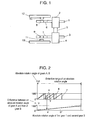
- Fig. 1 shows a structure of a detector of an absolute rotation angle and torque in accordance with an exemplary embodiment of the present invention.
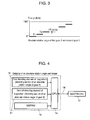
- Fig. 2 shows schematically how to find an absolute rotation angle.
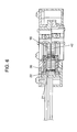
- Fig. 3 shows schematically how to find a torsion angle.
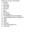
- Fig. 4 shows a block diagram of a detector in accordance with an exemplary embodiment of the present invention.
- Fig. 5 shows schematically how to correct an error.
- Fig. 6 shows a conventional detector of a rotation angle and torque.
- Fig. 1 shows a structure of a detector of an absolute rotation angle and torque in accordance with an exemplary embodiment of the present invention.
- a torsion-bar unit is formed of input shaft 2, torsion bar 5 and output shaft 4, and those elements are made of the same rigid body and placed concentrically.
- First gear 1 and second gear 3 are coupled to input shaft 2 and output shaft 4 respectively.
- First gear 1 engages with gear 6, and second gear 3 engages with gear 7.
- Gear 6 has first magnet 8 at its center, and gear 7 has second magnet 9 at its center.
- First magnet 8 and second magnet 9 are magnetized in one pole pair.
- Board 12 has first detecting element 10 of magnetism confronting first magnet 8, and board 13 has second detecting element 11 of magnetism confronting second magnet 9.
- First magnet 8 and first detecting element 10 form a first detecting section of an absolute rotation angle.
- Second magnet 9 and second detecting element 11 form a second detecting section of an absolute rotation angle.
- First gear 1 and second gear 3 have the same number of teeth "c”
- gear 6 has the number of teeth "a”
- gear 7 has the number of teeth "b" (a ⁇ b).
- rotation of input shaft 2 of the torsion-bar unit entails first gear 1 and gear 6 to rotate.
- First detecting element 10 detects magnetic field of first magnet 8, thereby calculating an absolute rotation angle of gear 6.
- Rotation of output shaft 4 entails second gear 3 and gear 7 to rotate.
- Second detecting element 11 detects magnetic field of second magnet 9, thereby calculating an absolute rotation angle of gear 7.
- Fig. 2 depicts a method of calculating an absolute rotation angle.
- the lateral axis represents absolute rotation angle “z" of first gear 1 and second gear 3.
- the upper column shows absolute rotation angles "x” and “y” of gear 6 and gear 7 respectively.
- the lower column shows a difference "x - y" between the absolute rotation angles of gear 6 and gear 7.
- the difference "x - y" draws a straight line and is uniquely related to absolute rotation angle "z", which can be thus calculated from the difference "x - y".
- difference T changes step by step as shown in Fig. 3 . If torsion bar 5 produces torsion ⁇ T, difference T changes by ⁇ T (c/a) with respect to the case where no torsion is produced, so that torsion angle ⁇ T can be calculated. This ⁇ T (c/a) is added to (x - y) shown in Fig. 2 , so that a detection accuracy of absolute rotation angle "z" can be improved. Torque can be calculated using torsion angle AT. When torsion angle ⁇ T exceeds a given allowance, the detector determines that an abnormality occurs and gives a warning.
- An absolute rotation angle and torque can be also detected in the condition of gear 6 and gear 7 having the same number of teeth, and first gear 1 has the number of teeth different from that of second gear 3.
- first detecting element 10 and second detecting element 11 are coupled to CPU 14, to which non-volatile memory EEPROM 15 is also coupled.
- CPU 14 is coupled to master CPU 17 via serial communication line 16 in order to output an absolute rotation angle and torque calculated by CPU 14.
- gear 6 and gear 7 are mounted to the torsion-bar unit, then an initial absolute rotation angle of gear 6 is calculated using a signal supplied from first detecting element 10, and that of gear 7 is calculated using a signal supplied from second detecting element 11.
- Those angles calculated are stored in EEPROM 15, and every time the power is turned on, the angles are read from EEPROM 15.
- a rotation angle starting from each one those initial absolute rotation angles is defined as respective absolute rotation angles of gear 6 and gear 7.
- absolute rotation angles (shown in solid lines) calculated by the detecting elements include errors due to a variety of factors with respect to respective correct absolute rotation angles (shown in broken lines), so that the following correction is provided: Gear 6 and gear 7 are mounted to the torsion-bar unit, then input shaft 2 is rotated with high accuracy, thereby obtaining a correction angle that is a difference between the correct absolute rotation angles and the absolute rotation angles of gear 6 and gear 7 calculated by the detecting elements.
- This correction angle is stored in EEPROM 15, and every time the power is turned on, this correction angle is read and added to the angles calculated by the detecting elements, so that an absolute rotation angle approximating to the correct one is obtainable.
- the detector of an absolute rotation angle and torque is suited to a power steering of cars.
Landscapes
- Engineering & Computer Science (AREA)
- Chemical & Material Sciences (AREA)
- Combustion & Propulsion (AREA)
- Transportation (AREA)
- Mechanical Engineering (AREA)
- Physics & Mathematics (AREA)
- General Physics & Mathematics (AREA)
- Electromagnetism (AREA)
- Measurement Of Length, Angles, Or The Like Using Electric Or Magnetic Means (AREA)
- Transmission And Conversion Of Sensor Element Output (AREA)
- Power Steering Mechanism (AREA)
Description
- The present invention relates to a detector, mounted to a torsion bar, for detecting an absolute rotation angle and torque simultaneously. The detector of the present invention is used in a power steering of cars.
-
Fig. 6 shows a conventional detector of a rotation angle and torque.Gear 18 is mounted to an input shaft (not shown) of a torsion bar. Gear 21 engaging withgear 18 includes round-shaped code plate 20 having numbers of magnetic poles.Code plate 20 rotates following the rotation of the input shaft. Detectingelement 22 of magnetism counts the number of poles rotating, thereby detecting a rotation angle of the input shaft.Gear 42 is mounted to an output shaft (not shown) of the torsion bar, and detects a rotation angle of the output shaft in the same manner as discussed above. When torque works to the torsion bar, thereby producing torsion on the shaft, a comparison of rotation angles between the input shaft and the output shaft will detect the torque. - However, a more accurate rotation angle requires
code plate 20 to have greater numbers of poles, so that the dimensions of the detector will become . greater, cf. e.g. the detector disclosed inDE-A-100 60 287 . Placement of detectingelements 22 in a radius direction oncode plate 20 will also enlarge the detector. The conventional detector discussed above cannot detect an absolute rotation angle. - From
US patent publication No. 5,930,905 a device for measuring the angle of a rotable body is known, wherein the absolute rotation angle is derived from the difference of rotation angles of two gears having a different number of teeths, both of which are engaging with the rotable body.US patent publication No. 6,578,437 further teaches that a third gear engaging with the end of a torsion bar may be employed to measure torque (see also the German patent applicationDE-A-198 34 322 ). In this configuration, however, three sensors for measuring rotation angles of three separate gears are required in order to measure both torque and absolute rotation angle. - It is thus an aim of the present invention to provide a configuration that allows for measuring both torque and absolute rotation angle with a reduced number of gears and sensors.
- This is achieved by the features of the independent claim. Prefered embodiments are subject matter of the dependent claims.
-
Fig. 1 shows a structure of a detector of an absolute rotation angle and torque in accordance with an exemplary embodiment of the present invention. -
Fig. 2 shows schematically how to find an absolute rotation angle. -
Fig. 3 shows schematically how to find a torsion angle. -
Fig. 4 shows a block diagram of a detector in accordance with an exemplary embodiment of the present invention. -
Fig. 5 shows schematically how to correct an error. -
Fig. 6 shows a conventional detector of a rotation angle and torque. - An exemplary embodiment of the present invention is demonstrated hereinafter with reference to the accompanying drawings.
-
Fig. 1 shows a structure of a detector of an absolute rotation angle and torque in accordance with an exemplary embodiment of the present invention. A torsion-bar unit is formed ofinput shaft 2,torsion bar 5 andoutput shaft 4, and those elements are made of the same rigid body and placed concentrically.First gear 1 andsecond gear 3 are coupled toinput shaft 2 andoutput shaft 4 respectively.First gear 1 engages withgear 6, andsecond gear 3 engages withgear 7. Gear 6 hasfirst magnet 8 at its center, andgear 7 hassecond magnet 9 at its center.First magnet 8 andsecond magnet 9 are magnetized in one pole pair.Board 12 has first detectingelement 10 of magnetism confrontingfirst magnet 8, andboard 13 has second detectingelement 11 of magnetism confrontingsecond magnet 9.First magnet 8 and first detectingelement 10 form a first detecting section of an absolute rotation angle.Second magnet 9 and second detectingelement 11 form a second detecting section of an absolute rotation angle.First gear 1 andsecond gear 3 have the same number of teeth "c",gear 6 has the number of teeth "a", andgear 7 has the number of teeth "b" (a≠b). - Next, an absolute rotation angle of
first gear 1 andsecond gear 3 as well as torque applied totorsion bar 5 are described. - In
Fig. 1 , rotation ofinput shaft 2 of the torsion-bar unit entailsfirst gear 1 andgear 6 to rotate. First detectingelement 10 detects magnetic field offirst magnet 8, thereby calculating an absolute rotation angle ofgear 6. Rotation ofoutput shaft 4 entailssecond gear 3 andgear 7 to rotate. Second detectingelement 11 detects magnetic field ofsecond magnet 9, thereby calculating an absolute rotation angle ofgear 7. -
Fig. 2 depicts a method of calculating an absolute rotation angle. The lateral axis represents absolute rotation angle "z" offirst gear 1 andsecond gear 3. The upper column shows absolute rotation angles "x" and "y" ofgear 6 andgear 7 respectively. The lower column shows a difference "x - y" between the absolute rotation angles ofgear 6 andgear 7. As shown inFig. 2 , the difference "x - y" draws a straight line and is uniquely related to absolute rotation angle "z", which can be thus calculated from the difference "x - y". - The ordinate axis of
Fig. 3 shows difference T which is found from the following equation: T = x - y b/a - When
torsion bar 5 does not have torsion, difference T changes step by step as shown inFig. 3 . Iftorsion bar 5 produces torsion ΔT, difference T changes by ΔT(c/a) with respect to the case where no torsion is produced, so that torsion angle ΔT can be calculated. This ΔT (c/a) is added to (x - y) shown in
Fig. 2 , so that a detection accuracy of absolute rotation angle "z" can be improved. Torque can be calculated using torsion angle AT. When torsion angle Δ T exceeds a given allowance, the detector determines that an abnormality occurs and gives a warning. - An absolute rotation angle and torque can be also detected in the condition of
gear 6 andgear 7 having the same number of teeth, andfirst gear 1 has the number of teeth different from that ofsecond gear 3. - As shown in
Fig. 4 , first detectingelement 10 and second detectingelement 11 are coupled toCPU 14, to whichnon-volatile memory EEPROM 15 is also coupled. On the other hand,CPU 14 is coupled to masterCPU 17 viaserial communication line 16 in order to output an absolute rotation angle and torque calculated byCPU 14. - It is desirable to mount
gear 6 andgear 7 with respective positions of zero-rotation angle of both the gears being agreed with each other; however, it requires so elaborate work that the following correction of zero-rotation angle takes the place of the work:Gear 6 andgear 7 are mounted to the torsion-bar unit, then an initial absolute rotation angle ofgear 6 is calculated using a signal supplied from first detectingelement 10, and that ofgear 7 is calculated using a signal supplied from second detectingelement 11. Those angles calculated are stored inEEPROM 15, and every time the power is turned on, the angles are read from EEPROM 15. A rotation angle starting from each one those initial absolute rotation angles is defined as respective absolute rotation angles ofgear 6 andgear 7. - Further as shown in
Fig. 5 , absolute rotation angles (shown in solid lines) calculated by the detecting elements include errors due to a variety of factors with respect to respective correct absolute rotation angles (shown in broken lines), so that the following correction is provided:Gear 6 andgear 7 are mounted to the torsion-bar unit, theninput shaft 2 is rotated with high accuracy, thereby obtaining a correction angle that is a difference between the correct absolute rotation angles and the absolute rotation angles ofgear 6 andgear 7 calculated by the detecting elements. This correction angle is stored inEEPROM 15, and every time the power is turned on, this correction angle is read and added to the angles calculated by the detecting elements, so that an absolute rotation angle approximating to the correct one is obtainable. - The detector of an absolute rotation angle and torque is suited to a power steering of cars.
Claims (7)
- A detector of an absolute rotation angle and torque, the detector comprising:a torsion-bar unit including an input shaft (2), an output shaft (4), and a torsion bar (5);a first gear (1) coupled to the input shaft (2);a second gear (3) coupled to the output shaft (4);a third gear (6) engaging with the first gear (1);a fourth gear (7) engaging with the second gear (3);a first detecting section (8, 10), placed at a center of third gear (6), for detecting an absolute rotation angle of the third gear (6);a second detecting section (9, 11), placed at a center of the fourth gear (7), for detecting an absolute rotation angle of the fourth gear (7); anda CPU (14) coupled to the first and the second detecting section (8, 9, 10, 11),
characterized in thateither the first gear (1) and the second gear (3) have an identical number of teeth and the third gear (6) has a number of teeth different from that of the fourth gear (7), or the first gear (1) has a number of teeth different from that of the second gear (3), and the third gear (6) and the fourth gear (7) have an identical number of teeth;the CPU (14) is adapted to compute an absolute rotation angle of the torsion-bar unit from a difference between respective absolute angles of the third gear (6) and the fourth gear (7),the CPU (14) is further adapted to compute a torque from a difference between an absolute rotation angle of the third gear (6) and that of the fourth gear (7) multiplied by either the teeth ratio of the third gear (6) and the fourth gear (7), or the teeth ratio of the first gear (1) and the second gear (3), whatever is different from one. - The detector according to claim 1, wherein the first detecting section (8, 10) includes a first magnet (8) and a first detecting element of magnetism (10) confronting the first magnet (8).
- The detector according to claim 1 or 2, wherein the second detecting section (9, 11) includes a second magnet (9) and a second detecting element of magnetism (11) confronting the second magnet (9).
- The detector according to any of claims 1 to 3, wherein the CPU (14) is further adapted to correct the computed absolute rotation angle based on the teeth ratio of the first and the third gear (6) multiplied by a torsion angle derived from the computed torque.
- The detector according to any of claims 1 to 4, further comprising
a nonvolatile memory for storing in advance respective initial absolute rotation angles of the third gear (6) and the fourth gear (7), and
wherein the CPU (14) is further adapted to take the stored initial absolute rotation angles into account when computing the absolute rotation angle and the torque. - The detector according to any of claims 1 to 5, further comprising
a nonvolatile memory for storing in advance a plurality of correction angles for the third (6) and the fourth gear (7), said correction values indicating differences between actual absolute rotation angles of the third (6) and the fourth gear (7) and absolute rotation angles detected by the first and the second detecting sections (8, 9, 10, 11), respectively, and
wherein the CPU (14) is further adapted to take the stored plurality of correction angles into account when computing the absolute rotation angle and the torque. - The detector according to any of claims 1 to 6, wherein the CPU (14) is further adapted to give a warning of an abnormality when a difference between an absolute rotation angle of the third gear (6) and that of the fourth gear (7) multiplied by either the teeth ratio of the third gear (6) and the fourth gear (7), or the teeth ratio of the first gear (1) and the second gear (3), whatever is different from one, exceeds a predetermined allowance.
Applications Claiming Priority (3)
| Application Number | Priority Date | Filing Date | Title |
|---|---|---|---|
| JP2003309794 | 2003-09-02 | ||
| JP2003309794A JP4474872B2 (en) | 2003-09-02 | 2003-09-02 | Absolute rotation angle and torque detector |
| PCT/JP2004/012910 WO2005024369A1 (en) | 2003-09-02 | 2004-08-31 | Device for detecting absolute rotation angle and torque |
Publications (3)
| Publication Number | Publication Date |
|---|---|
| EP1536217A1 EP1536217A1 (en) | 2005-06-01 |
| EP1536217A4 EP1536217A4 (en) | 2006-09-20 |
| EP1536217B1 true EP1536217B1 (en) | 2008-08-20 |
Family
ID=34269622
Family Applications (1)
| Application Number | Title | Priority Date | Filing Date |
|---|---|---|---|
| EP04772859A Expired - Lifetime EP1536217B1 (en) | 2003-09-02 | 2004-08-31 | Device for detecting absolute rotation angle and torque |
Country Status (6)
| Country | Link |
|---|---|
| US (1) | US7258027B2 (en) |
| EP (1) | EP1536217B1 (en) |
| JP (1) | JP4474872B2 (en) |
| CN (1) | CN100460842C (en) |
| DE (1) | DE602004015916D1 (en) |
| WO (1) | WO2005024369A1 (en) |
Cited By (1)
| Publication number | Priority date | Publication date | Assignee | Title |
|---|---|---|---|---|
| WO2017148534A1 (en) * | 2016-03-04 | 2017-09-08 | Thyssenkrupp Ag | Ripple minimization by proper as/ts magnet arrangement in electric power assisted steering apparatus |
Families Citing this family (30)
| Publication number | Priority date | Publication date | Assignee | Title |
|---|---|---|---|---|
| JP2007183121A (en) * | 2006-01-05 | 2007-07-19 | Matsushita Electric Ind Co Ltd | Rotation angle and torque detection device |
| DE102006006359A1 (en) * | 2006-02-11 | 2007-08-16 | Leopold Kostal Gmbh & Co. Kg | Angle of rotation sensor and method for determining the absolute angular position of a body rotatable over several rounds |
| JP4607033B2 (en) * | 2006-02-28 | 2011-01-05 | 株式会社日本自動車部品総合研究所 | Rotation angle detector |
| JP2007256140A (en) * | 2006-03-24 | 2007-10-04 | Matsushita Electric Ind Co Ltd | Rotation angle / rotation torque detector |
| JP4597907B2 (en) * | 2006-05-16 | 2010-12-15 | 株式会社デンソー | Rotation angle detector |
| US7562591B2 (en) * | 2006-06-26 | 2009-07-21 | KRS Technologies Co. | Steering angle sensor |
| JP4763540B2 (en) * | 2006-07-21 | 2011-08-31 | 東洋電装株式会社 | Rudder angle sensor |
| EP1910155B1 (en) * | 2006-07-25 | 2013-05-01 | LG Innotek Co., Ltd | Steering angle sensing apparatus and method thereof |
| US7841231B2 (en) | 2006-07-25 | 2010-11-30 | Lg Innotek Co., Ltd. | Steering angle sensing apparatus and method thereof |
| FR2919385B1 (en) * | 2007-07-24 | 2009-10-09 | Moving Magnet Tech Mmt | NON-CONTACT MAGNETIC SENSOR WITH ABSOLUTE MULTITOUR POSITION WITH THROUGH SHAFT |
| US8607650B2 (en) * | 2008-07-14 | 2013-12-17 | Continental Teves Ag & Co. Ohg | Torque sensor arrangement with rotational angle index detection |
| DE102009022712A1 (en) * | 2009-05-26 | 2010-12-02 | Bourns, Inc., Riverside | Torsion angle sensor for measurement of torsion angle of i.e. steering column parts, in steering wheel of motor vehicle, has measuring wheels coupled with shafts via torsion wheels that are connected with shafts in torque proof manner |
| JP5892493B2 (en) * | 2009-06-29 | 2016-03-23 | ボルボ ラストバグナー アーベー | Method and system for assisting a vehicle driver while driving |
| CN102155932B (en) * | 2010-07-01 | 2012-06-27 | 长春设备工艺研究所 | Dual-coder angle detecting system for torsion test of torsion shaft |
| JP2012173268A (en) * | 2011-02-24 | 2012-09-10 | Honda Motor Co Ltd | Angle detector and electric power steering apparatus |
| DE102011106339B4 (en) * | 2011-03-04 | 2012-12-06 | Auma Riester Gmbh & Co. Kg | Measuring device for detecting the absolute rotation angle of a rotating object to be measured |
| DE102011052043B4 (en) * | 2011-07-21 | 2022-06-09 | Bourns, Inc. | Angle of rotation and torsion angle sensor |
| CN102506698B (en) * | 2011-11-04 | 2014-03-12 | 合肥工业大学 | Contactless corner-torque sensor |
| DE102012022869A1 (en) * | 2012-11-21 | 2014-05-22 | Volkswagen Aktiengesellschaft | Steering angle sensor for device for combined acquisition of angle and rotational torque of steering column, has magnetic code track formed by magnetic ring of torque sensor connected to shaft portion and magnetic field sensor |
| CN103112496A (en) * | 2013-01-10 | 2013-05-22 | 青岛科技大学 | Pin-hinged vehicle steering angle detection device |
| CN103085876A (en) * | 2013-01-10 | 2013-05-08 | 青岛科技大学 | Steering angel detecting device of pin roll hinged vehicle |
| DE102013001829B4 (en) | 2013-02-04 | 2014-08-21 | Bourns, Inc. | Angle of rotation and torsion angle sensor |
| JP6083428B2 (en) | 2014-12-16 | 2017-02-22 | トヨタ自動車株式会社 | Electric power steering device for vehicle |
| CN106541985A (en) * | 2016-10-13 | 2017-03-29 | 北京联合大学 | For the auto-pilot controller and its vehicle of unmanned electric vehicle |
| WO2018123277A1 (en) * | 2016-12-27 | 2018-07-05 | 株式会社東海理化電機製作所 | Position sensor and shift lever device |
| DE102017116764A1 (en) | 2017-07-25 | 2019-01-31 | Danfoss Power Solutions Aps | Steering wheel angle sensor and method for detecting errors in a steering wheel angle sensor |
| JP7000263B2 (en) * | 2018-06-20 | 2022-01-19 | 株式会社東海理化電機製作所 | Initial setting method and initial setting device |
| WO2020133471A1 (en) * | 2018-12-29 | 2020-07-02 | 深圳市优必选科技有限公司 | Rotation angle detection method and device |
| CN115675645B (en) * | 2022-10-12 | 2025-08-05 | 上海精传电子科技有限公司 | An ASIL-D grade EPS torque angle sensor based on gear structure |
| KR20250090624A (en) * | 2023-12-13 | 2025-06-20 | 엘지이노텍 주식회사 | sensing, apparatus |
Citations (4)
| Publication number | Priority date | Publication date | Assignee | Title |
|---|---|---|---|---|
| EP0338559A2 (en) * | 1988-04-22 | 1989-10-25 | Hitachi, Ltd. | Torque detecting apparatus with abnormality signal |
| DE10060287A1 (en) * | 1999-12-06 | 2001-06-07 | Bosch Gmbh Robert | Determination of the angle, angular velocity, and or torque of a rotating body, especially a motor vehicle steering wheel shaft by use of optical code traces on the rotating body and optical sensors for reading a code offset |
| US6578437B1 (en) * | 1998-08-07 | 2003-06-17 | Robert Bosch Gmbh | Sensor array for detecting rotation angle and/or torque |
| US20030155627A1 (en) * | 2002-02-15 | 2003-08-21 | Shigetoshi Fukaya | Adjustment-circuit embedded semiconductor sensor and torsion bar type torque sensor system |
Family Cites Families (11)
| Publication number | Priority date | Publication date | Assignee | Title |
|---|---|---|---|---|
| JPH05231968A (en) * | 1992-02-24 | 1993-09-07 | Ono Sokki Co Ltd | Torque detector |
| DE19506938A1 (en) * | 1995-02-28 | 1996-08-29 | Bosch Gmbh Robert | Method and device for measuring the angle of a rotatable body |
| JPH10142082A (en) * | 1996-11-07 | 1998-05-29 | Toyoda Mach Works Ltd | Torque sensor |
| DE19834322B4 (en) | 1998-07-30 | 2015-06-11 | Robert Bosch Gmbh | Method and device for determining the torque acting on a shaft |
| AU775247B2 (en) * | 1999-12-06 | 2004-07-22 | Robert Bosch Gmbh | Device for measuring the angle and/or the angular velocity of a rotatable body and/or the torque acting upon said body |
| JP2003270062A (en) * | 2002-03-13 | 2003-09-25 | Koyo Seiko Co Ltd | Angle-of-rotation detecting device, torque detecting device, and steering system |
| JP2004020370A (en) * | 2002-06-17 | 2004-01-22 | Matsushita Electric Ind Co Ltd | Torque detector |
| JP2004144716A (en) * | 2002-10-28 | 2004-05-20 | Koyo Seiko Co Ltd | Rotation angle detection device and torque detection device |
| JP3938902B2 (en) * | 2002-11-27 | 2007-06-27 | 株式会社ジェイテクト | Angle detection device and torque sensor including the same |
| JP4120425B2 (en) * | 2003-02-28 | 2008-07-16 | 株式会社ジェイテクト | Rotation angle detection device and torque detection device |
| JP2005077305A (en) * | 2003-09-02 | 2005-03-24 | Matsushita Electric Ind Co Ltd | Rotation angle and torque detection device |
-
2003
- 2003-09-02 JP JP2003309794A patent/JP4474872B2/en not_active Expired - Fee Related
-
2004
- 2004-08-31 DE DE602004015916T patent/DE602004015916D1/en not_active Expired - Lifetime
- 2004-08-31 US US10/528,586 patent/US7258027B2/en not_active Expired - Fee Related
- 2004-08-31 CN CNB2004800009509A patent/CN100460842C/en not_active Expired - Fee Related
- 2004-08-31 WO PCT/JP2004/012910 patent/WO2005024369A1/en not_active Ceased
- 2004-08-31 EP EP04772859A patent/EP1536217B1/en not_active Expired - Lifetime
Patent Citations (4)
| Publication number | Priority date | Publication date | Assignee | Title |
|---|---|---|---|---|
| EP0338559A2 (en) * | 1988-04-22 | 1989-10-25 | Hitachi, Ltd. | Torque detecting apparatus with abnormality signal |
| US6578437B1 (en) * | 1998-08-07 | 2003-06-17 | Robert Bosch Gmbh | Sensor array for detecting rotation angle and/or torque |
| DE10060287A1 (en) * | 1999-12-06 | 2001-06-07 | Bosch Gmbh Robert | Determination of the angle, angular velocity, and or torque of a rotating body, especially a motor vehicle steering wheel shaft by use of optical code traces on the rotating body and optical sensors for reading a code offset |
| US20030155627A1 (en) * | 2002-02-15 | 2003-08-21 | Shigetoshi Fukaya | Adjustment-circuit embedded semiconductor sensor and torsion bar type torque sensor system |
Cited By (2)
| Publication number | Priority date | Publication date | Assignee | Title |
|---|---|---|---|---|
| WO2017148534A1 (en) * | 2016-03-04 | 2017-09-08 | Thyssenkrupp Ag | Ripple minimization by proper as/ts magnet arrangement in electric power assisted steering apparatus |
| US10800452B2 (en) | 2016-03-04 | 2020-10-13 | Thyssenkrupp Ag | Ripple minimization by proper AS/TS magnet arrangement in electric power assisted steering apparatus |
Also Published As
| Publication number | Publication date |
|---|---|
| EP1536217A4 (en) | 2006-09-20 |
| EP1536217A1 (en) | 2005-06-01 |
| CN100460842C (en) | 2009-02-11 |
| WO2005024369A1 (en) | 2005-03-17 |
| JP4474872B2 (en) | 2010-06-09 |
| CN1701221A (en) | 2005-11-23 |
| US7258027B2 (en) | 2007-08-21 |
| DE602004015916D1 (en) | 2008-10-02 |
| US20060042403A1 (en) | 2006-03-02 |
| JP2005077304A (en) | 2005-03-24 |
Similar Documents
| Publication | Publication Date | Title |
|---|---|---|
| EP1536217B1 (en) | Device for detecting absolute rotation angle and torque | |
| EP2491335B1 (en) | Multi-turn sensor | |
| US6507188B1 (en) | Device and method for detecting the relative position of a rotatable body | |
| US6519549B1 (en) | Method and device for determining absolute angular position of a rotating body | |
| EP3160827B1 (en) | An electric power assisted steering system | |
| EP1830155A1 (en) | Rotation angle detection device and rotation angle correction method | |
| KR101829057B1 (en) | Angle sensor | |
| EP3160826B1 (en) | An electric power assisted steering system | |
| CN101115968A (en) | Rotation angle detection device and rotation angle correction method | |
| CN103201596A (en) | Device adapted to provide an indication of the angular position of an input member by multiple turns | |
| EP1544580B1 (en) | Angle detecting sensor | |
| US20050075828A1 (en) | Rotation angle sensor | |
| JP2006220529A (en) | Absolute rotation angle and torque detector | |
| KR20150082920A (en) | Angle sensor and torque angle sensor including the same | |
| EP1818659A1 (en) | Rotation angle and torque detection device | |
| JPH0353114A (en) | Position detector | |
| EP1845352A1 (en) | Device for detecting rotation angle and torque | |
| EP2058628A2 (en) | Method and apparatus to monitor position of a rotatable shaft | |
| KR20130128549A (en) | Angle sensor | |
| JPH09101175A (en) | Multi-turn absolute encoder | |
| WO2007094196A1 (en) | Torque detector and rotating angle detector | |
| KR100827818B1 (en) | Method of measuring rotation angle of shaft rotor | |
| US7370540B2 (en) | Rotation angle sensor, in particular for an electrical steering system of an industrial truck | |
| JP2005201712A (en) | Rotation angle and torque detection device | |
| JP2006275558A (en) | Torque detection device with absolute rotation angle detection function |
Legal Events
| Date | Code | Title | Description |
|---|---|---|---|
| PUAI | Public reference made under article 153(3) epc to a published international application that has entered the european phase |
Free format text: ORIGINAL CODE: 0009012 |
|
| 17P | Request for examination filed |
Effective date: 20050318 |
|
| AK | Designated contracting states |
Kind code of ref document: A1 Designated state(s): AT BE BG CH CY CZ DE DK EE ES FI FR GB GR HU IE IT LI LU MC NL PL PT RO SE SI SK TR |
|
| AX | Request for extension of the european patent |
Extension state: AL HR LT LV MK |
|
| RIN1 | Information on inventor provided before grant (corrected) |
Inventor name: OIKE, KOJI Inventor name: USHIHARA, MASAHARUMATSUSHITA ELECTRIC INDUSTRIAL Inventor name: UEHIRA, KIYOTAKA |
|
| A4 | Supplementary search report drawn up and despatched |
Effective date: 20060823 |
|
| DAX | Request for extension of the european patent (deleted) | ||
| RBV | Designated contracting states (corrected) |
Designated state(s): DE FR GB |
|
| 17Q | First examination report despatched |
Effective date: 20061207 |
|
| GRAP | Despatch of communication of intention to grant a patent |
Free format text: ORIGINAL CODE: EPIDOSNIGR1 |
|
| GRAS | Grant fee paid |
Free format text: ORIGINAL CODE: EPIDOSNIGR3 |
|
| GRAA | (expected) grant |
Free format text: ORIGINAL CODE: 0009210 |
|
| AK | Designated contracting states |
Kind code of ref document: B1 Designated state(s): DE FR GB |
|
| REG | Reference to a national code |
Ref country code: GB Ref legal event code: FG4D |
|
| REF | Corresponds to: |
Ref document number: 602004015916 Country of ref document: DE Date of ref document: 20081002 Kind code of ref document: P |
|
| RAP2 | Party data changed (patent owner data changed or rights of a patent transferred) |
Owner name: PANASONIC CORPORATION |
|
| PLBE | No opposition filed within time limit |
Free format text: ORIGINAL CODE: 0009261 |
|
| STAA | Information on the status of an ep patent application or granted ep patent |
Free format text: STATUS: NO OPPOSITION FILED WITHIN TIME LIMIT |
|
| 26N | No opposition filed |
Effective date: 20090525 |
|
| PGFP | Annual fee paid to national office [announced via postgrant information from national office to epo] |
Ref country code: FR Payment date: 20100824 Year of fee payment: 7 |
|
| PGFP | Annual fee paid to national office [announced via postgrant information from national office to epo] |
Ref country code: GB Payment date: 20100825 Year of fee payment: 7 |
|
| GBPC | Gb: european patent ceased through non-payment of renewal fee |
Effective date: 20110831 |
|
| REG | Reference to a national code |
Ref country code: FR Ref legal event code: ST Effective date: 20120430 |
|
| PG25 | Lapsed in a contracting state [announced via postgrant information from national office to epo] |
Ref country code: FR Free format text: LAPSE BECAUSE OF NON-PAYMENT OF DUE FEES Effective date: 20110831 Ref country code: GB Free format text: LAPSE BECAUSE OF NON-PAYMENT OF DUE FEES Effective date: 20110831 |
|
| PGFP | Annual fee paid to national office [announced via postgrant information from national office to epo] |
Ref country code: DE Payment date: 20150825 Year of fee payment: 12 |
|
| REG | Reference to a national code |
Ref country code: DE Ref legal event code: R119 Ref document number: 602004015916 Country of ref document: DE |
|
| PG25 | Lapsed in a contracting state [announced via postgrant information from national office to epo] |
Ref country code: DE Free format text: LAPSE BECAUSE OF NON-PAYMENT OF DUE FEES Effective date: 20170301 |