EP1536212A2 - Akustischer Doppler Strömungsprofilmesser - Google Patents
Akustischer Doppler Strömungsprofilmesser Download PDFInfo
- Publication number
- EP1536212A2 EP1536212A2 EP04027962A EP04027962A EP1536212A2 EP 1536212 A2 EP1536212 A2 EP 1536212A2 EP 04027962 A EP04027962 A EP 04027962A EP 04027962 A EP04027962 A EP 04027962A EP 1536212 A2 EP1536212 A2 EP 1536212A2
- Authority
- EP
- European Patent Office
- Prior art keywords
- ultrasound
- wave
- fluid
- tube body
- wedge
- Prior art date
- Legal status (The legal status is an assumption and is not a legal conclusion. Google has not performed a legal analysis and makes no representation as to the accuracy of the status listed.)
- Withdrawn
Links
Images



Classifications
-
- G—PHYSICS
- G01—MEASURING; TESTING
- G01F—MEASURING VOLUME, VOLUME FLOW, MASS FLOW OR LIQUID LEVEL; METERING BY VOLUME
- G01F1/00—Measuring the volume flow or mass flow of fluid or fluent solid material wherein the fluid passes through a meter in a continuous flow
- G01F1/66—Measuring the volume flow or mass flow of fluid or fluent solid material wherein the fluid passes through a meter in a continuous flow by measuring frequency, phase shift or propagation time of electromagnetic or other waves, e.g. using ultrasonic flowmeters
- G01F1/662—Constructional details
-
- A—HUMAN NECESSITIES
- A61—MEDICAL OR VETERINARY SCIENCE; HYGIENE
- A61B—DIAGNOSIS; SURGERY; IDENTIFICATION
- A61B8/00—Diagnosis using ultrasonic, sonic or infrasonic waves
- A61B8/48—Diagnostic techniques
- A61B8/485—Diagnostic techniques involving measuring strain or elastic properties
Definitions
- the present invention relates to a clamp-on type acoustic Doppler current profiler that transmits ultrasound from an ultrasound transducer provided exterior to a tube body into to-be-measured fluid in the tube body, and uses the Doppler effect to measure the flow rate profile of the fluid in a non-contact manner.
- a clamp-on type ultrasound flow meter is a flow meter in which an ultrasound transducer is attached to a part of the outer circumferential face of a tube body (e.g., piping) in order to measure, from the exterior of the tube body, the flow rate of the fluid moving in the tube body.
- Clamp-on type ultrasound flow meters are mainly classified into a first type that utilizes the difference in propagation time and a second type that utilizes the Doppler effect.
- the first type use a method by which ultrasound is reciprocated in the tube body so as to move along a path that crosses, on a slanted line, the fluid moving in the tube body, and then, the difference between the time in which the ultrasound propagates along the outward route and the time in which the ultrasound propagates along the return route is used to measure the flow rate of the fluid.
- the second type uses a method in which, based on the assumption that suspended particles and/or air bubbles included in the fluid move at the same speed as the fluid itself, the movement speed of the suspended particles or the like is used to measure the flow rate of the fluid (in the following the term "suspended particles" is used in a broad sense covering also air bubbles etc).
- this method is based on the phenomenon according to which, when ultrasound is transmitted into the fluid, the frequency of the ultrasound is changed by the Doppler effect in accordance with the movement speed of the suspended particles when the ultrasound is reflected by the suspended particles. Thereafter, the frequency of the reflected ultrasound is detected to measure the movement speed of the suspended particles (i.e., the speed of the fluid), thereby measuring the flow rate profile and/or the flow rate.
- the Doppler ultrasound flow meter shown in Figure 6 includes an ultrasound velocity profile measurement unit (hereinafter referred to as a UVP unit) 10 that measures the flow rate of fluid 22 in a piping 21 in a non-contact manner.
- This UVP unit 10 includes: an ultrasound transmission means 11 for transmitting to the fluid 22 an ultrasound pulse having a required frequency (basic frequency f 0 ) along a measurement line ML; a flow rate profile measurement circuit 12 for receiving the ultrasound echo reflected from the measurement region of the ultrasound pulse transmitted into the fluid 22 to measure the flow rate profile of the fluid 22 in the measurement region; a computer 31 (e.g., microcomputer, CPU, MPU) for calculating the flow rate profile of the fluid 22 to integrate it in the radial direction of the piping 21, thereby measuring the flow rate of the fluid 22 depending on time; and a display apparatus 32 for displaying the output from this computer 31 in chronological order.
- a computer 31 e.g., microcomputer, CPU, MPU
- the ultrasound transmission means 11 includes, for example, a signal generator 15 consisting of an oscillator 13 for generating an electric signal having the basic frequency f 0 (e.g., 1 MHz, 2 MHz, 4 MHz) and an emitter 14 for outputting the electric signal from this oscillator 13 as periodic pulses having a pulse frequency F rpf and a predetermined cycle of 1/F rpf , and this signal generator 15 inputs the pulsed electric signal to an ultrasound transducer 16.
- a signal generator 15 consisting of an oscillator 13 for generating an electric signal having the basic frequency f 0 (e.g., 1 MHz, 2 MHz, 4 MHz) and an emitter 14 for outputting the electric signal from this oscillator 13 as periodic pulses having a pulse frequency F rpf and a predetermined cycle of 1/F rpf , and this signal generator 15 inputs the pulsed electric signal to an ultrasound transducer 16.
- the ultrasound transducer 16 transmits the ultrasound pulses having the basic frequency f 0 to the fluid 22 in the piping 21 along the measurement line ML.
- This ultrasound pulse is a straight beam having a beam width of 5 mm for example that has very little dispersion.
- the ultrasound transducer 16 is a transmitter/receiver that is designed also to receive the ultrasound echo generated when a transmitted ultrasound pulse is reflected by reflectors in the fluid 22.
- the above reflectors are the suspended particles mentioned above that are uniformly included in the fluid 22 (i.e., foreign matter having a different acoustic impedance from that of the fluid 22).
- the ultrasound echo received by the ultrasound transducer 16 is converted by this transducer 16 into an electric echo signal.
- This electric echo signal is amplified by an amplifier 17 in the UVP unit 10 and digitized by an AD converter 18, and then, this digital echo signal is input into the flow rate profile measurement circuit 12.
- the electric signal having the basic frequency f 0 from the oscillator 13 and digitized by the AD converter 18 is also input to the flow rate profile measurement circuit 12. Based on the difference of frequency (Doppler shift) between these signals, the flow rate is measured to calculate the flow rate profile of the fluid 22 in the measurement region along the measurement line ML.
- the flow rate profile of this measurement region can be corrected in accordance with the oblique angle ⁇ of the ultrasound transducer 16 (oblique angle to the direction perpendicular to the longitudinal direction of the piping 21), thereby measuring the flow rate profile of the fluid 22 in the cross section of the piping 21.
- the ultrasound transducer 16 is inclined by the oblique angle ⁇ to the direction along which the fluid 22 flows, and transmits an ultrasound pulse having the basic frequency f 0 into the piping.
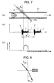
- this ultrasound pulse collides with and is reflected by the reflectors, i.e., turns into an ultrasound echo "a", which is received by the ultrasound transducer 16, as shown in Figure 7(B).
- reference numeral "b” denotes a multiple reflection echo reflected by the tube wall of the piping 21 into which an ultrasound pulse is transmitted
- reference numeral "c” denotes a multiple reflection echo created at the opposing tube wall of the piping 21.
- the ultrasound transducer 16 transmits ultrasound pulses having a cycle of (1/F rpf ) as shown in the drawing.
- the echo signal "a" received by the ultrasound transducer 16 is filtered and the Doppler shift method is used to measure the flow rate profile along the measurement line ML, thereby providing the display as shown in Figure 7(C).
- This flow rate profile is measured by the flow rate profile measurement circuit 12 of the UVP unit 10 and is displayed by a display apparatus 32 via the computer 31.
- the Doppler shift method uses the phenomenon according to which, when an ultrasound pulse is transmitted to the fluid 22 flowing in the piping 21, this ultrasound pulse is reflected by reflectors mixed in or uniformly dispersed in the fluid 22 to turn into an ultrasound echo, and the frequency of this ultrasound echo is shifted by a magnitude proportional to the flow rate.
- the flow rate profile signal of the fluid 22 measured by the flow rate profile measurement circuit 12 is transmitted to the computer 31 and the flow rate profile signal can be integrated in the radial direction of the piping 21, thereby calculating the flow rate of the fluid 22.
- m(t) ⁇ vx (r ⁇ t) ⁇ r ⁇ dr ⁇ d ⁇
- vx(r ⁇ t) represents the velocity component at time t from the center on the cross section of the piping in the tube axis direction for distance r and angle ⁇ .
- the flow rate profile of the fluid 22 is obtained by subjecting the ultrasound echo to signal processing for calculation. Due to this reason, this ultrasound echo must contain only an acoustic signal, thus requiring the elimination of acoustic noise and electric noise.
- Acoustic noise having an influence on this ultrasound echo includes noise caused by the reflection or scattering between the mediums having different acoustic impedances, for example, and noise caused by longitudinal and shear waves generated in solid matter (e.g., the piping material).
- Solid matter e.g., metal generally includes therein two types of acoustic waves.
- One is called a compressional wave, a longitudinal wave having a displacement in the same direction as the direction along which the wave propagates, and the other is called a shear wave, a shear wave having a displacement in the direction perpendicular to the direction along which the wave propagates.
- Figure 9 shows the structure in accordance with the measurement conditions described in [4].
- an acrylic wedge 42 is fixed with an ultrasound transducer 41 such that this ultrasound transducer 41 is inclined, with the angle ⁇ in , to a direction perpendicular to the longitudinal direction of a piping 43.
- ultrasound from the wedge 42 to the piping 43 has an incidence angle of ⁇ in .
- fluid 44 shown in Figure 9 is water while the piping 43 is made of stainless steel.
- the velocity of sound in water is about 1,500 m/s
- the velocity of the longitudinal wave in stainless steel is about 5,750 m/s
- the velocity of the shear wave in stainless steel is about 3,206 m/s.
- the velocity of the longitudinal wave in acrylic is 2,730 m/s.
- the critical angles ⁇ c of the longitudinal wave and the shear wave are calculated based on the above-described mathematical expression 4.
- the critical angle of the longitudinal wave at the interface between the wedge 42 and the piping 43 is 28.3°
- the critical angle of the shear wave at the interface between the wedge 42 and the piping 43 is 58.4°.
- the ultrasound transducer 41 transmits an acoustic wave having an oblique angle (incidence angle) ⁇ in of 20° for example
- the wedge 42 and the piping 43 both of which are solids, have a longitudinal wave and a shear wave at the interface therebetween.
- the incidence angle ⁇ in at the above interface is equal to or smaller than the critical angles of both the longitudinal wave and the shear wave.
- the piping 43 has therein the propagation of both the longitudinal wave and the shear wave.
- the longitudinal wave has a refraction angle (output angle) ⁇ pl of 46.1° while the shear wave has a refraction angle ⁇ ps of 23.7°.
- medium 1 is made of aluminum while medium 2 is water in Figure 8.
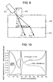
- Figure 10 is a drawing shown in [5] showing the relation, when an aluminum plate corresponding to the medium 1 and water corresponding to the medium 2 have a shear wave at the interface therebetween, between the incidence angle and the energy reflection coefficient (reflectivity) and the energy transmission coefficient (transmission rate).
- the wave SV represents a shear wave
- the wave L represents a longitudinal wave.
- total reflection is not caused and the longitudinal wave is transmitted even when the incidence angle of the shear wave exceeds 28°.
- Figure 11 shows the relation, when the aluminum plate and water have a longitudinal wave at the interface therebetween, between the incidence angle and the reflectivity and the transmission rate. As can be seen from Figure 11, only the longitudinal wave is transmitted.
- Figure 12 shows the behavior of the ultrasound echo in the structure of Figure 9.
- the ultrasound echo from the reflectors in water returns from water to the ultrasound transducer 41 via the same route as that through which ultrasound is transmitted from the piping 43 into water.
- the ultrasound echo has an incidence angle ⁇ f of 10.84° when the ultrasound is transmitted from water into the aluminum piping 43, and thus, both a longitudinal wave and a shear wave are generated, as can be seen from Figure 2 (which will be described later).
- the four ultrasound echoes propagating in the wedge 42 are transmitted into the ultrasound transducer 41 with a time difference in accordance with the acoustic velocity of the ultrasound transducer 41 in the propagation route.
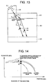
- ⁇ pl represents the refraction angle of the longitudinal wave at the interface between the fluid (water) 44 and the piping 43
- ⁇ ps represents the refraction angle of the shear wave
- ⁇ wl represents the refraction angle of the longitudinal wave at the interface between the piping 43 and the wedge 42
- ⁇ ws represents the refraction angle of the shear wave.
- the ultrasound echo received by the ultrasound transducer 41 has a time axis corresponding to the position along the direction of the diameter of the piping 43.
- the longitudinal wave and the shear wave in the piping 43 have different acoustic velocities.
- the ultrasound echo received by the ultrasound transducer 41 at a certain time is obtained by synthesizing the flow rate at point A' of the fluid 44 in the piping 43 measured by the shear wave in Figure 13 with the flow rate at point A' (which is at a different position from that of point A along the direction of the diameter of the piping 43) of the fluid 44 in the piping 43 measured by the longitudinal wave.
- the flow rate calculated based on the ultrasound echo received by the ultrasound transducer 41 at a certain time is actually obtained by synthesizing the flow rates at point A and point A' (which are at different positions), and thus, the flow rate profile and consequently the flow rate of the fluid 44 in the piping 43 cannot be measured accurately.
- the Doppler ultrasound flow meter for calculating the flow rate by measuring the flow rate profile in the piping had a problem in that an acoustic wave transmitted from the ultrasound transducer generates a longitudinal wave and a shear wave in a piping that are transmitted along two measurement lines into the fluid, which causes the ultrasound echoes from the respective reflectors received by the Doppler ultrasound flow meter, thus causing the flow rate profile to be measured inaccurately and deteriorating the measurement accuracy.
- the object is achieved by eliminating, from the ultrasound echoes caused by a longitudinal wave and a shear wave propagating along two measurement lines in the tube body (e.g., piping), the ultrasound echo caused by the longitudinal wave.
- the longitudinal wave component of the ultrasound that is transmitted from an ultrasound transducer and that propagates from a wedge to a tube body can be eliminated, thus the fluid has therein only ultrasound along one measurement line, caused by the shear wave in the tube body.
- the ultrasound echo caused by reflection of the shear wave by the reflectors in the fluid appears and thus the ultrasound echo caused by the longitudinal wave is not received by the ultrasound transducer, thus reducing the acoustic noise.
- the longitudinal wave component of the ultrasound echo from the fluid propagating in the tube body can be eliminated and the ultrasound transducer can receive only the shear wave of the ultrasound echo, thus reducing the acoustic noise as in the case of the invention according to claim 1.
- the two embodiments according to claims 1 and 2 can both improve the measurement accuracy of the flow rate profile, which enables determination of the flow rate with a higher accuracy.
- Figure 1 shows the main part of a first embodiment. Although the structure shown in Figure 1 is substantially the same as that shown in Figure 9, Figure 12, Figure 13, etc., different reference numerals are used, for clarity.
- reference numeral 51 denotes an ultrasound oscillator, i.e., an ultrasound transducer, which generates an acoustic wave.
- This ultrasound oscillator 51 is made of a piezoelectric material, such as PZT (e.g., zircon, lead titanate) and operates both as an ultrasound transmitter and an ultrasound receiver.
- Reference numeral 52 denotes a wedge made of a resin material in which an acoustic wave can propagate (e.g., acrylic, epoxy resin, polyvinyl chloride, polyphenylene sulfide).
- the wedge 52 has an inclined plane 52a at the upper end thereof, and the ultrasound oscillator 51 is fixed to the inclined plane 52a by an epoxy adhesive agent or the like.
- the inclined plane 52a is inclined such that the oblique angle of the ultrasound oscillator 51 to the direction perpendicular to the longitudinal direction of the piping 53 (incidence angle of the ultrasound pulse at the interface between the wedge 52 and the piping 53) is equal to ⁇ in .
- Reference numeral 54 denotes a fluid whose flow rate is to be measured.
- the speed of sound in acrylic is about 2,730 m/s
- the velocity of the longitudinal wave in aluminum is about 6,420 m/s while the velocity of the shear wave therein is about 3,040 m/s
- the speed of sound in water is about 1,500 m/s.
- the piping 53 may be made of aluminum or other metal in which an acoustic wave can propagate (e.g., iron, steel, ductile cast iron, stainless steel, copper, lead, brass).
- an acoustic wave can propagate (e.g., iron, steel, ductile cast iron, stainless steel, copper, lead, brass).
- the critical angle of the longitudinal wave is 25.2° while the critical angle of the shear wave is 63.9° when ultrasound is transmitted from the wedge 52 into the piping 53.
- the oblique angle ⁇ in of the ultrasound oscillator 51 incidence angle at the interface between the wedge 52 and the piping 53
- the above critical angle range i.e., 25.2° ⁇ ⁇ in ⁇ 63.9°
- the ultrasound oscillator 51 does not receive an ultrasound echo caused by a longitudinal wave, thus reducing the acoustic noise included in the flow rate to be measured. This improves the measurement accuracy of the flow rate profile and enables the flow rate to be calculated with a higher accuracy.
- the above incidence angle ⁇ in exceeds 25.2° (which is the critical angle of the longitudinal wave) and thus the longitudinal wave is totally reflected at the interface between the wedge 52 and the piping 53 and does not propagate in the piping 53.
- the shear wave propagates in the piping 53 with the refraction angle of 51.9°.
- the longitudinal wave reflected by the reflectors i.e., the ultrasound echo, is also transmitted into the piping 53 at an incidence angle of 22.8°.
- Figure 2 shows the relation between the incidence angle of an ultrasound wave from water into the piping and the energy transmission coefficient (transmission rate) of the longitudinal wave and the shear wave in the piping.
- the incidence angle to the piping 53 of 22.8° is equal to or higher than the critical angle of the longitudinal wave, and thus, the longitudinal wave is totally reflected at the interface between water and the piping 53. Specifically, the longitudinal wave does not propagate in the piping 53.
- the piping 53 has therein only one measurement line of the ultrasound echo produced by the shear wave and the ultrasound oscillator 51 receives the ultrasound echo of this shear wave, thus reducing the conventional acoustic noise caused by the longitudinal wave.
- the measurement accuracy of the flow rate profile can be improved over conventional cases by improving the oblique angle of the ultrasound oscillator 51 (incidence angle to the piping 53) to eliminate the longitudinal wave in the piping 53.
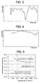
- Figure 3 and Figure 4 show examples in which the flow rate at a position along the radial direction of the piping 53 is measured when the oblique angle of the ultrasound oscillator 51 is 15° ( Figure 3) and when the oblique angle of the ultrasound oscillator 51 is 45° ( Figure 4).
- the piping 53 When the oblique angle of Figure 3 is 15°, the piping 53 has therein the longitudinal wave and the shear wave and thus the ultrasound echo received by the ultrasound oscillator 51 includes a large amount of acoustic noise, causing the measurement values of flow rate profile to be unstable, which deteriorates the measurement accuracy.
- Figure 5 shows the comparison, with regard to the measurement errors that occurred when the flow rate output of an electromagnetic flow meter was measured based on the flow rate profile, between a case in which the oblique angle of the ultrasound oscillator 51 is similarly 45° according to this embodiment, and a case in which the oblique angle of the ultrasound oscillator 51 is 15°, as in conventional cases.
- this embodiment also significantly improves the measurement errors when compared to conventional cases.
- the critical angle of the longitudinal wave in the ultrasound echo transmitted into the aluminum piping 53 after being reflected by the reflectors in water is 13.5° while the critical angle of the shear wave is 29.6° when the acoustic velocity in water is 1500[m/s].
- the acoustic wave from the piping 53 into water has an incidence angle that is equal to or higher than 13.5° and that is equal to or lower than 29.6°, then only the shear wave element is transmitted into the piping 53 and the longitudinal wave element is eliminated when the ultrasound echo is transmitted from water into the piping 53, thus reducing the acoustic noise caused by the longitudinal wave.
- the ultrasound oscillator 51 receives only the ultrasound echo of the shear wave in the piping 53, and this allows the piping 53 to carry reduced acoustic noise caused by the longitudinal wave, provides the measurement of a flow rate profile with a higher accuracy, and improves the accuracy of the measurement of a flow meter.
- the wedge may be made of a metal in which an acoustic wave can propagate (e.g., iron, steel, cast iron, stainless steel, copper, lead, aluminum, brass), and the piping may be made of a resin in which an acoustic wave can propagate (e.g., polyvinyl chloride, acrylic, FRP, polyethylene, Teflon (registered trademark), tar epoxy, mortar).
- a metal in which an acoustic wave can propagate e.g., iron, steel, cast iron, stainless steel, copper, lead, aluminum, brass
- the piping may be made of a resin in which an acoustic wave can propagate (e.g., polyvinyl chloride, acrylic, FRP, polyethylene, Teflon (registered trademark), tar epoxy, mortar).
- one embodiment of the present invention of may be defined as a clamp-on type acoustic Doppler current profiler, characterized in that ultrasound is transmitted from an ultrasound transducer provided exterior to a tube body to a to-be-measured fluid within the tube body, to measure the flow rate profile of the to-be-measured fluid by using a mechanism whereby the frequency of ultrasound is changed by the Doppler effect when ultrasound is reflected by reflectors existing in the to-be-measured fluid, wherein a wedge through which an acoustic wave can propagate is provided between a longitudinal ultrasound wave-generating source of the ultrasound transducer and the tube body, and the source for generating an acoustic wave is fixed to the wedge at an inclination such that, when the velocities of the longitudinal wave and the shear wave of the ultrasound propagating in the tube body are equal to or higher than the velocity of the longitudinal wave in the wedge, the incidence angle of the ultrasound transmitted from the wedge into the tube body is equal to or higher than the critical angle of the longitudinal wave that
- Another embodiment of the present invention of may be defined as a clamp-on type acoustic Doppler current profiler, comprising:
Landscapes
- Physics & Mathematics (AREA)
- Electromagnetism (AREA)
- Fluid Mechanics (AREA)
- General Physics & Mathematics (AREA)
- Measuring Volume Flow (AREA)
Applications Claiming Priority (2)
| Application Number | Priority Date | Filing Date | Title |
|---|---|---|---|
| JP2003396755 | 2003-11-27 | ||
| JP2003396755A JP2005156401A (ja) | 2003-11-27 | 2003-11-27 | クランプオン型ドップラー式超音波流速分布計 |
Publications (2)
| Publication Number | Publication Date |
|---|---|
| EP1536212A2 true EP1536212A2 (de) | 2005-06-01 |
| EP1536212A3 EP1536212A3 (de) | 2007-02-28 |
Family
ID=34463824
Family Applications (1)
| Application Number | Title | Priority Date | Filing Date |
|---|---|---|---|
| EP04027962A Withdrawn EP1536212A3 (de) | 2003-11-27 | 2004-11-25 | Akustischer Doppler Strömungsprofilmesser |
Country Status (5)
| Country | Link |
|---|---|
| US (1) | US20050154307A1 (de) |
| EP (1) | EP1536212A3 (de) |
| JP (1) | JP2005156401A (de) |
| CN (1) | CN1645060A (de) |
| CA (1) | CA2488009A1 (de) |
Cited By (1)
| Publication number | Priority date | Publication date | Assignee | Title |
|---|---|---|---|---|
| EP1621856A2 (de) | 2004-07-20 | 2006-02-01 | Fuji Electric Systems Co., Ltd. | Doppler-Ultraschallströmungsgeschwindigkeitsprofilmesser |
Families Citing this family (15)
| Publication number | Priority date | Publication date | Assignee | Title |
|---|---|---|---|---|
| US20060243280A1 (en) * | 2005-04-27 | 2006-11-02 | Caro Richard G | Method of determining lung condition indicators |
| WO2006117780A2 (en) * | 2005-04-29 | 2006-11-09 | Oren Gavriely | Cough detector |
| US7581453B2 (en) * | 2006-12-29 | 2009-09-01 | General Electric Company | Ultrasonic flow meter system |
| US20150176399A1 (en) * | 2012-08-27 | 2015-06-25 | Rensselaer Polytechnic Institute | Method and apparatus for acoustical power transfer and communication |
| DE102013006825A1 (de) * | 2012-09-20 | 2014-03-20 | Em-Tec Gmbh | Messvorrichtung basierend auf akustischen Strömungsmessverfahren in einem Pumpensystem und Verfahren zur Herstellung einer Messvorrichtung |
| JP5155490B1 (ja) * | 2012-10-09 | 2013-03-06 | 東京計装株式会社 | 超音波流量計 |
| US20140275826A1 (en) * | 2013-03-15 | 2014-09-18 | Covidien Lp | Photoacoustic sensors for patient monitoring |
| JP5971428B2 (ja) * | 2013-10-23 | 2016-08-17 | 富士電機株式会社 | 流体計測装置 |
| JP2015232519A (ja) * | 2014-06-10 | 2015-12-24 | アズビル株式会社 | クランプオン式超音波流量計及び流量の計測方法 |
| CN105158339B (zh) * | 2015-08-18 | 2018-09-25 | 中国工程物理研究院化工材料研究所 | 纵横波一体化超声波探头、弹性模量及分布的测试系统和测试方法 |
| CN112014591B (zh) * | 2020-09-27 | 2025-05-16 | 华电电力科学研究院有限公司 | 一种超声波流速测量系统、方法以及装置 |
| KR102783980B1 (ko) * | 2022-05-27 | 2025-03-19 | 서울대학교산학협력단 | 배관 내 이물질 높이를 측정하기 위한 측정 장치 |
| CN115112918A (zh) * | 2022-06-29 | 2022-09-27 | 河北大学 | 一种大口径污水管道多点流速测量装置和测量方法 |
| CN115326134B (zh) * | 2022-07-27 | 2025-09-16 | 景德镇陶瓷大学 | 一种基于脉冲多普勒技术识别管道内气液两相流流型的方法 |
| CN119434968A (zh) * | 2025-01-08 | 2025-02-14 | 中国石油大学(华东) | 深水钻井超声多普勒气侵监测装置及其换能器布设方法 |
Family Cites Families (9)
| Publication number | Priority date | Publication date | Assignee | Title |
|---|---|---|---|---|
| US3575050A (en) * | 1968-12-04 | 1971-04-13 | Panametrics | Fluid flowmeter |
| US3987674A (en) * | 1975-01-03 | 1976-10-26 | Joseph Baumoel | Transducer structure and support for fluid measuring device |
| US3973152A (en) * | 1975-04-03 | 1976-08-03 | The United States Of America As Represented By The United States Energy Research And Development Administration | Ultrasonic transducer with laminated coupling wedge |
| US4195517A (en) * | 1978-12-18 | 1980-04-01 | The Foxboro Company | Ultrasonic flowmeter |
| US4467659A (en) * | 1982-08-12 | 1984-08-28 | Joseph Baumoel | Transducer having metal housing and employing mode conversion |
| JP2002520584A (ja) * | 1998-07-10 | 2002-07-09 | パナメトリクス・インコーポレイテッド | 誘導モードによる流量測定システム |
| US6293156B1 (en) * | 1999-01-22 | 2001-09-25 | Panametrics, Inc. | Coherent multi-path flow measurement system |
| US6626049B1 (en) * | 1999-04-01 | 2003-09-30 | Panametrics, Inc. | Clamp-on steam/gas flow meter |
| GB2363455B (en) * | 2000-06-12 | 2002-10-16 | Schlumberger Holdings | Flowmeter |
-
2003
- 2003-11-27 JP JP2003396755A patent/JP2005156401A/ja active Pending
-
2004
- 2004-11-19 CA CA002488009A patent/CA2488009A1/en not_active Abandoned
- 2004-11-25 EP EP04027962A patent/EP1536212A3/de not_active Withdrawn
- 2004-11-26 CN CNA2004100956295A patent/CN1645060A/zh active Pending
- 2004-11-29 US US10/999,224 patent/US20050154307A1/en not_active Abandoned
Cited By (1)
| Publication number | Priority date | Publication date | Assignee | Title |
|---|---|---|---|---|
| EP1621856A2 (de) | 2004-07-20 | 2006-02-01 | Fuji Electric Systems Co., Ltd. | Doppler-Ultraschallströmungsgeschwindigkeitsprofilmesser |
Also Published As
| Publication number | Publication date |
|---|---|
| JP2005156401A (ja) | 2005-06-16 |
| US20050154307A1 (en) | 2005-07-14 |
| CA2488009A1 (en) | 2005-05-27 |
| CN1645060A (zh) | 2005-07-27 |
| EP1536212A3 (de) | 2007-02-28 |
Similar Documents
| Publication | Publication Date | Title |
|---|---|---|
| CN1725019B (zh) | 钳式多普勒超声波流速分布仪 | |
| US5533408A (en) | Clamp-on ultrasonic volumetric flowmeter | |
| US4397194A (en) | Ultrasonic flowmeter including means to measure pipe geometry | |
| TW577978B (en) | Doppler-type ultrasonic flowmeter | |
| US20050154307A1 (en) | Apparatus and method for measuring a fluid velocity profile using acoustic doppler effect | |
| CA1123088A (en) | Ultrasonic flowmeter | |
| US7412902B2 (en) | Device for determination and/or monitoring of the volumetric and/or mass flow of a medium and having coupling element including two element portions | |
| WO1996024029A1 (en) | Ultrasonic flowmeter 'w' | |
| JP3795510B2 (ja) | 超音波流速分布計及び流量計、超音波流速分布及び流量測定方法並びに超音波流速分布及び流量測定処理プログラム | |
| US6820500B2 (en) | Small pipe bore ultrasonic flowmeter detector | |
| Han et al. | Studies on the transducers of clamp-on transit-time ultrasonic flow meter | |
| JP6207428B2 (ja) | 超音波式音速測定装置及び超音波式音速測定方法 | |
| EP1726920A1 (de) | Doppler-ultraschall-durchflussmesser | |
| JP2005241494A (ja) | クランプオン型ドップラー式超音波流速分布計 | |
| Szebeszczyk | Application of clamp-on ultrasonic flowmeter for industrial flow measurements | |
| JP4296947B2 (ja) | ドップラー式超音波流速分布計の超音波送受信ユニット | |
| JP4827008B2 (ja) | 超音波流量計、超音波トランスジューサ、超音波送受信ユニットおよび超音波流量計を用いた流量測定方法 | |
| EP4439019B1 (de) | Ultraschall-durchflussmesser und messverfahren | |
| KR20100007218A (ko) | 초음파 유량측정용 배관장치 | |
| EP1701139A1 (de) | Ultraschall-strömungsmesser, strömungsmessverfahren und computerprogramm | |
| JP2005195374A (ja) | 超音波流量計およびそれに用いるくさび | |
| JP2005195371A (ja) | 超音波流量計および超音波流量計用の吸音材 | |
| JP2005345358A (ja) | 超音波流量計およびそれに用いるくさび | |
| JP2005351828A (ja) | ドップラー式超音波流量計に用いられる楔ユニット | |
| JP2005241437A (ja) | ドップラー式超音波流量計 |
Legal Events
| Date | Code | Title | Description |
|---|---|---|---|
| PUAI | Public reference made under article 153(3) epc to a published international application that has entered the european phase |
Free format text: ORIGINAL CODE: 0009012 |
|
| AK | Designated contracting states |
Kind code of ref document: A2 Designated state(s): AT BE BG CH CY CZ DE DK EE ES FI FR GB GR HU IE IS IT LI LU MC NL PL PT RO SE SI SK TR |
|
| AX | Request for extension of the european patent |
Extension state: AL HR LT LV MK YU |
|
| PUAL | Search report despatched |
Free format text: ORIGINAL CODE: 0009013 |
|
| AK | Designated contracting states |
Kind code of ref document: A3 Designated state(s): AT BE BG CH CY CZ DE DK EE ES FI FR GB GR HU IE IS IT LI LU MC NL PL PT RO SE SI SK TR |
|
| AX | Request for extension of the european patent |
Extension state: AL HR LT LV MK YU |
|
| AKX | Designation fees paid | ||
| STAA | Information on the status of an ep patent application or granted ep patent |
Free format text: STATUS: THE APPLICATION IS DEEMED TO BE WITHDRAWN |
|
| 18D | Application deemed to be withdrawn |
Effective date: 20070829 |
|
| REG | Reference to a national code |
Ref country code: DE Ref legal event code: 8566 |