EP1536169B1 - Elektromagnetisches Ventil - Google Patents
Elektromagnetisches Ventil Download PDFInfo
- Publication number
- EP1536169B1 EP1536169B1 EP20030027541 EP03027541A EP1536169B1 EP 1536169 B1 EP1536169 B1 EP 1536169B1 EP 20030027541 EP20030027541 EP 20030027541 EP 03027541 A EP03027541 A EP 03027541A EP 1536169 B1 EP1536169 B1 EP 1536169B1
- Authority
- EP
- European Patent Office
- Prior art keywords
- armature
- valve
- flat spring
- spring
- sleeve
- Prior art date
- Legal status (The legal status is an assumption and is not a legal conclusion. Google has not performed a legal analysis and makes no representation as to the accuracy of the status listed.)
- Expired - Lifetime
Links
- 239000012530 fluid Substances 0.000 claims description 5
- 230000036316 preload Effects 0.000 claims description 3
- 230000001105 regulatory effect Effects 0.000 claims 1
- 238000007789 sealing Methods 0.000 description 5
- 230000006835 compression Effects 0.000 description 2
- 238000007906 compression Methods 0.000 description 2
- 238000004519 manufacturing process Methods 0.000 description 2
- 230000002093 peripheral effect Effects 0.000 description 2
- 238000004804 winding Methods 0.000 description 2
- FIKFLLIUPUVONI-UHFFFAOYSA-N 8-(2-phenylethyl)-1-oxa-3,8-diazaspiro[4.5]decan-2-one;hydrochloride Chemical compound Cl.O1C(=O)NCC11CCN(CCC=2C=CC=CC=2)CC1 FIKFLLIUPUVONI-UHFFFAOYSA-N 0.000 description 1
- 229910000639 Spring steel Inorganic materials 0.000 description 1
- 239000012141 concentrate Substances 0.000 description 1
- 238000011161 development Methods 0.000 description 1
- 230000018109 developmental process Effects 0.000 description 1
- 238000007598 dipping method Methods 0.000 description 1
- 230000005284 excitation Effects 0.000 description 1
- 239000007789 gas Substances 0.000 description 1
- 239000000696 magnetic material Substances 0.000 description 1
- 238000003466 welding Methods 0.000 description 1
Images
Classifications
-
- F—MECHANICAL ENGINEERING; LIGHTING; HEATING; WEAPONS; BLASTING
- F16—ENGINEERING ELEMENTS AND UNITS; GENERAL MEASURES FOR PRODUCING AND MAINTAINING EFFECTIVE FUNCTIONING OF MACHINES OR INSTALLATIONS; THERMAL INSULATION IN GENERAL
- F16K—VALVES; TAPS; COCKS; ACTUATING-FLOATS; DEVICES FOR VENTING OR AERATING
- F16K31/00—Actuating devices; Operating means; Releasing devices
- F16K31/02—Actuating devices; Operating means; Releasing devices electric; magnetic
- F16K31/06—Actuating devices; Operating means; Releasing devices electric; magnetic using a magnet, e.g. diaphragm valves, cutting off by means of a liquid
- F16K31/0644—One-way valve
- F16K31/0655—Lift valves
Definitions
- the invention relates to a device for controlling a fluid or gaseous medium of the type specified in the preamble of claim 1.
- a known control device of this type with a 2/2-way valve ( DE 100 39 066 A1 ) has a valve housing with a valve inlet and valve outlet, which communicate with each other via a valve chamber.
- a valve opening enclosing a valve seat is formed, which is governed for flow control of the medium by a valve member which determines by more or less far from the valve seat, the flow through the valve opening flow rate.
- the control of the valve member by means of an electromagnet, which has an anchor sleeve and a seated on the anchor sleeve excitation winding or magnetic coil.
- an anchor plug or counter-anchor is fixedly arranged and an armature displaceably guided, which is rigidly connected via a transfer ram with the valve member.
- the anchor slides with a sliding ring on the inner wall of the anchor sleeve.
- the transfer ram is guided in a slide bearing fixed in the anchor sleeve. This is a precise, low-backlash movement of the anchor be achieved.
- the valve member is pressed in the closed state of the valve by a valve closing spring on the valve seat.
- the valve closing spring is supported, on the one hand, on the armature and, on the other hand, on an adjusting screw screwed into the counter-anchor, by means of which the pretensioning of the valve closing spring can be adjusted.
- the mutually facing ends of the armature and counter-anchor are conical and engage each other, whereby the magnetic force acting between armature and counter-armature is independent of the stroke of the armature.
- the invention has for its object to improve a device for controlling a fluid or gaseous medium of the type mentioned so that an extremely low-friction and precise guidance of the armature in the armature sleeve while maintaining a reliable tightness of the valve is achieved in the closed state.
- the control device has the advantage that through the holder with minimal radial play of the anchor by means of at least two flat springs, the anchor over its entire stroke across the inner wall of the Anchor sleeve touched at any point. At the same time a tight support of the valve member is ensured on the valve seat by the valve closing spring.
- a conical helical compression spring valve closing spring in a introduced into the anchor, central blind hole and is based on the one hand on the blind hole bottom and on the other hand to an adjusting device for setting their Bias off.
- the adjusting device advantageously comprises an adjusting pin which can be screwed into the anchor plug and has a centering pin and a support shoulder surrounding the centering pin for the valve closing spring at its free front end. Due to the conical design of the valve closing spring occurs during armature stroke no friction between the valve closing spring and the hole wall of the blind hole, whereby the low friction of the armature is further increased during the stroke.
- a flat spring engages radially without play on a front end of the armature.
- a flat spring is advantageously inserted in a form-fitting manner in a concentric recess introduced in the end face of the armature and centered on the adjusting pin of the adjusting device.
- the flat spring lies exclusively with its outer edge region on an annular shoulder formed in the recess and is clamped on the annular shoulder by means of a hold-down device inserted into the recess, through which the adjusting pin of the adjusting device is passed.
- the flat spring has a central opening into which the guide pin formed on the alignment pin protrudes positively, wherein the flat spring rests with its surrounding the central opening edge region on the support shoulder on the adjusting pin and is clamped by the valve closing spring.
- the axial bias of the flat spring is varied along with the bias of the closing spring.
- a centering sleeve is pushed onto the guide pin, which engages positively in the central opening of the flat spring and is pressed by the valve closing spring on the support shoulder of the adjusting pin.
- the flat spring lies with its peripheral area surrounding the central opening on the hold-down.
- the axial bias of the flat spring is not changed by adjusting the closing force of the valve closing spring by means of the adjusting pin.
- the flat spring in a valve housing arranged concentrically to the valve seat receptacle positively and is centered on the dipping into the receptacle end side of the armature and preferably clamped between the valve member directly attached to the end face of the armature and the armature ,
- the flat spring only with a central region on an opposite the end face of the armature axially projecting annular shoulder, while the outer edge region of the flat spring rests on a radially projecting in the receiving annular shoulder.
- the flat spring can also be centered with a central opening via a front end of the anchor projecting, conically tapering collar and fixed by the valve member.
- the receptacle is formed by a recess introduced into the valve housing.
- the anchor sleeve immersed with an end portion in the recess and biases the flat spring on the annular shoulder.
- the receptacle is formed by a screwed into the end portion of the anchor sleeve receiving sleeve, wherein the anchor sleeve is in turn immersed with its end portion in a recess formed in the valve housing, but rotatably fixed in the recess.
- the valve member has a seal holder and a seal plate received by the seal holder, which communicates with the valve seat.
- the seal holder is preferably with a Spigot pressed in a central blind hole, which is introduced from the front side of the anchor.
- an adjusting device for adjusting the armature stroke is provided.
- Such adjusting device is realized in a simple manner by a threaded connection between the recess formed in the valve housing and the end portion of the anchor sleeve which dips into the recess. By turning the anchor sleeve this is moved more or less axially, which can vary the distance between the armature and anchor plug.
- a 2/2-way valve 11 for controlling a fluid or gaseous medium has a 2/2-way valve 11 and an electromagnet 12 for actuating the 2/2-way valve 11.
- the 2/2-way valve 11 has a valve housing 13 with a valve inlet 14 and a valve outlet 15, which communicate with each other via a valve chamber 16.
- a valve opening 17 is formed, which is enclosed by a valve seat 18 which cooperates for flow control of the medium with a valve member 19 which determines by more or less far from the valve seat 18, the flow through the valve opening 17 flow rate.
- the control of the valve member 19 is effected by means of the electromagnet 12, which preferably has a proportional behavior.
- the electromagnet 12 has an anchor sleeve 20, in which an anchor plug 21 is arranged and an armature stopper 21 axially opposite armature 22 is received axially displaceable.
- Anchor sleeve 20 and anchor plug 21 may be integrally formed with each other.
- the anchor sleeve 20 is surrounded by a field winding or magnetic coil 23 which is fixed axially immovably to the anchor sleeve 20.
- the mutually facing ends of armature 22 and anchor plug 21 are conical and interlock, whereby the force acting between armature 22 and anchor plug 21 magnetic force is independent of the stroke of the armature 22.
- the anchor sleeve 20 is immersed with an end portion 201 in an inserted in the valve housing 13, diameter-graded recess 24, the diameter smaller, the lower valve chamber 16 forms.
- the end portion 201 is located in the larger diameter, upper portion of the recess 24 and is supported on an annular shoulder 241 formed by the diameter gradation in the recess 24.
- the end portion 201 of the anchor sleeve 20 is sealed relative to the recess 24 by means of a sealing ring 25.
- the anchor sleeve 20 is secured to the valve housing 13 by means of a pushed over the anchor sleeve 20 mounting ring 26 which engages over the sealing ring 25 radially and this presses against an end portion 201 formed on the outer annular shoulder.
- the fastening ring 26 is od on the valve body 13, for example by welding, screwing. Like., Set.
- the armature 22 is held by means of two flat springs 27, 28 in the anchor sleeve 20 so that it rests with minimal radial play without contact in the anchor sleeve 20 and is axially displaceable, without touching the inner wall of the anchor sleeve 20.
- the one flat spring 27 is arranged at the upper front end and the other flat spring 28 at the lower end face of the armature 22.
- the valve member 19 is attached.
- the valve member 19 has a seal holder 30 with a pin 301 integrally formed thereon and a sealing plate 31 received in the seal holder 30, which cooperates with the valve seat 18.
- the seal holder 30 is pressed with its pin 301 into a blind hole 32 made in the end face of the armature 22.
- concentric collar 33 is formed, which is designed as a truncated cone, which tapers towards the free end. Between the collar 33 and the seal holder 30 which is a flat spring 28 is clamped.
- valve closing spring 29 The tightness between the sealing plate 31 and the valve seat 18 in the closed state of the valve 11 is brought about by a valve closing spring 29.
- the valve closing spring 29 is inserted into a blind hole 35, which is introduced from the anchor plug 21 facing the front end of the armature 22 in the armature 22. Trained as a helical compression spring valve closing spring 29 is supported on the one hand on the bottom of the blind hole 35 and on the other hand on an adjusting pin 36 of an adjusting device for adjusting the biasing force of the valve closing spring 29.
- an axially projecting guide pin 361 is formed, which is annularly surrounded by a radial support shoulder 362.
- a centering sleeve 37 is pushed, which rests with a flange 371 on the support shoulder 362.
- the adjusting pin 36 facing the end of the valve closing spring 29 is guided on the centering sleeve 37 and is supported on the flange 371, this pressing against the support shoulder 362 from.
- the adjusting pin 36 is screwed in the anchor plug 21, so that by turning the adjusting pin 36, the valve closing spring 29 more or less can be compressed.
- the adjusting pin 36 passes with its protruding from the stopper 21, the free end through a hold-down 38, which dips into a introduced in the end face of the armature 22, concentric recess 39 and rests there on an opening 39 formed in the annular shoulder 391.
- the upper and lower flat spring 27, 28 are formed identically with different diameters.
- An embodiment of the flat springs 27, 28 is in Fig. 4 shown in plan view.
- Each flat spring 27, 28 is for example made of spring steel with a thickness of 0.05 - 0.3 mm and provided with a central opening 40.
- 27 or 28 spirally extending recesses 41 are incorporated with different radial spacing in the flat spring.
- the flat spring 27 has a smaller diameter than the flat spring 28 and is positively inserted into the recess 39 in the armature 22, so that they can perform no radial relative movement to the armature 22. Its outer edge region rests on the annular shoulder 391 formed in the recess 39 and is clamped by the hold-down device 38.
- the flange 371 of the centering sleeve 37 concentrates the flat spring 27 on the adjusting pin 36.
- the larger diameter, lower flat spring 28 is positively inserted into the recess 24 in the valve housing 13 and lies with its outer edge region on the annular shoulder 241 of the recess 24 and is tightened by the anchor sleeve 20 on the annular shoulder 241.
- the flat spring 28 is placed with its central opening 40 on the conical flange 33 and secured by the seal holder 30 against removal, so that the flat spring 28 is centered on the lateral surface of the collar 33.
- the peripheral region of the flat spring 28 surrounding the central opening 40 can rest on the annular end face of the collar 33, and the pin 301 of the seal holder 30 can pass through the central opening 40 in a form-fitting manner so that the flat spring 28 is centered on the pin 301 of the seal holder 30 and on the other hand is clamped between the armature 22 and the seal holder 30.
- the control device is modified insofar as that introduced into the armature 22 blind hole 35 for receiving the valve closing spring 29 is designed with a much larger diameter and at the same time forms the recess 39 for receiving the upper flat spring 27 and the hold-38.
- the blind hole 35 tapers at least in the region of the recess 39 in the direction of the hole bottom.
- the hold-down device 38 and the flat spring 27, which is supported by its outer edge region on an annular collar on the underside of the hold-down 38 form fit.
- the flat spring 27 abuts with its central edge 40 enclosing, inner edge region of the support shoulder 362 of the adjusting pin 36 and is centered by the guide pin 361 of the adjusting pin 36.
- the valve closing spring 39 is designed as a conical spring which widens downwards and is supported by the upper flat spring 27 on the support shoulder 362 on the adjusting pin 36.
- the adjusting device for adjusting the bias of the valve closing spring 29 also acts on the upper flat spring 27 and changes the axial biasing force with.
- the conical shape of the valve closing spring 29 friction between the valve closing spring 29 and the hole wall of the blind hole 35 is avoided.
- an adjusting device for adjusting the armature stroke This consists in the simplest case of a screw thread 42 between the present in the valve housing 13 recess 24 and the end portion 201 of the anchor sleeve 20.
- the anchor sleeve 20 can move axially by turning in the recess 24, so that the distance between the anchor plug 21 on the one hand and the Anchor 22 and the preferably made of non-magnetic material hold-down 38 on the other hand, and thus the stroke of the armature 22 can be changed.
- the control device is modified insofar as additionally an adjusting device for adjusting the axial preload of the lower flat spring 28 is provided.
- the anchor sleeve 20 is in turn tightly inserted with its end portion 201 in the present in the valve housing 13 recess 24, but is rotatably disposed in the recess 24 about its sleeve axis.
- a receiving sleeve 43 by means of a thread 44 can be screwed.
- a radial annular shoulder 431 is formed, on which the lower flat spring 28 rests with its outer edge region.
- the flat spring 28 is centered here via its central opening 40 by means of the journal 301 of the seal holder 30 on the armature 22 and clamped with its central opening 40 enclosing the edge region between the seal holder 30 and the annular end face of the collar 33 at anchor 22. If the anchor sleeve 20 is now rotated so that the receiving sleeve 43, which is held non-rotatably in the recess 39, screwed down through the thread 44, the outer edge of the lower flat spring 28 by the annular shoulder 431 on the receiving sleeve 43 down pressed, so that the axial biasing force of the lower flat spring 28 increases.
- a suitably directed bias of the flat springs 27, 28 can be used to support the opening stroke or to increase the sealing force of the valve member 19.
Landscapes
- Engineering & Computer Science (AREA)
- General Engineering & Computer Science (AREA)
- Mechanical Engineering (AREA)
- Magnetically Actuated Valves (AREA)
Description
- Die Erfindung betrifft eine Vorrichtung zur Regelung eines fluiden oder gasförmigen Mediums der im Oberbegriff des Anspruchs 1 angegebenen Gattung.
- Eine bekannte Regelungsvorrichtung dieser Art mit einem 2/2-Wegeventil (
DE 100 39 066 A1 ) weist ein Ventilgehäuse mit einem Ventileingang und Ventilausgang auf, die über eine Ventilkammer miteinander in Verbindung stehen. In der Ventilkammer ist ein eine Ventilöffnung umschließender Ventilsitz ausgebildet, der zur Durchflussregelung des Mediums von einem Ventilglied beherrscht wird, das durch mehr oder weniger weites Abheben vom Ventilsitz die durch die Ventilöffnung strömende Durchflussmenge bestimmt. Die Steuerung des Ventilglieds erfolgt mittels eines Elektromagneten, der eine Ankerhülse und eine auf der Ankerhülse sitzende Erregerwicklung oder Magnetspule aufweist. In der Ankerhülse ist ein Ankerstopfen oder Gegenanker fest angeordnet und ein Anker verschieblich geführt, der über einen Übertragungsstößel starr mit dem Ventilglied verbunden ist. Der Anker gleitet mit einem Gleitring an der Innenwand der Ankerhülse. Der Übertragungsstößel ist in einem in der Ankerhülse festgelegten Gleitlager geführt. Dadurch soll eine präzise, spielarme Bewegung des Ankers erreicht werden. Das Ventilglied wird im Schließzustand des Ventils durch eine Ventilschließfeder auf den Ventilsitz aufgepresst. Die Ventilschließfeder stützt sich einerseits am Anker und andererseits an einer in den Gegenanker eingeschraubten Justierschraube ab, mittels der die Vorspannung der Ventilschließfeder eingestellt werden kann. Die einander zugekehrten Enden von Anker und Gegenanker sind konisch ausgebildet und greifen ineinander, wodurch die zwischen Anker und Gegenanker wirkende Magnetkraft unabhängig vom Hub des Ankers ist. - Es ist ein direktwirkendes 2/2-Wege-Proportional- bzw. Stetig-Ventil in Gestalt eines Hubanker-Magnetventils bekannt (Thomas Sattler: "Wo Gase dosiert werden", MSR Magazin 12/2002, S. 38), bei dem der Anker durch Magnetkraft gegen eine Feder angezogen wird und direkt auf den Ventilsitz wirkt. Statt Gleitringen kommen Formfedern zum Einsatz, so dass selbst in dieser Größenordnung keine nennenswerte Reibung auftritt. Beide Formfedern übernehmen die Führung des Ankers, lediglich jedoch die obere Feder dessen Rückstellung. Diese obere Feder soll somit zugleich auch die Dichtheit des Ventils im Schließzustand herbeiführen und sicherstellen. Dementsprechend ist die Federkraft zu dimensionieren.
- Der Erfindung liegt die Aufgabe zugrunde, eine Vorrichtung zur Regelung eines fluiden oder gasförmigen Mediums der eingangs genannten Art so zu verbessern, dass eine extrem reibungsarme und präzise Führung des Ankers in der Ankerhülse unter Beibehaltung einer zuverlässigen Dichtheit des Ventils im Schließzustand erreicht wird.
- Die Aufgabe ist erfindungsgemäß durch die Merkmale im Anspruch 1 gelöst.
- Die erfindungsgemäße Regelungsvorrichtung hat den Vorteil, dass durch die Halterung mit minimalem Radialspiel des Ankers mittels mindestens zweier Flachfedern der Anker über seinen Gesamthub hinweg die Innenwand der Ankerhülse an keiner Stelle berührt. Gleichzeitig wird durch die Ventilschließfeder eine dichte Auflage des Ventilglieds auf dem Ventilsitz sichergestellt.
- Zweckmäßige Ausführungsformen der erfindungsgemäßen Regelungsvorrichtung mit vorteilhaften Weiterbildungen und Ausgestaltungen der Erfindung sind in den weiteren Ansprüchen angegeben.
- Gemäß einer vorteilhaften Ausführungsform der Erfindung liegt die vorzugsweise als konische Schrauben-Druckfeder ausgebildete Ventilschließfeder in einem in den Anker eingebrachten, zentralen Sackloch ein und stützt sich einerseits am Sacklochboden und andererseits an einer Justiereinrichtung zur Einstellung ihrer Vorspannung ab. Die Justiereinrichtung umfasst in vorteilhafter Weise einen Justierstift, der im Ankerstopfen verschraubbar ist und an seinem freien Stirnende einen Zentrierzapfen und eine den Zentrierzapfen umgebende Auflageschulter für die Ventilschließfeder aufweist. Durch die konische Ausbildung der Ventilschließfeder tritt beim Ankerhub keine Reibung zwischen der Ventilschließfeder und der Lochwand des Sacklochs auf, wodurch die Reibungsarmut des Ankers beim Hub noch zusätzlich gesteigert wird.
- Gemäß einer vorteilhaften Ausführungsform der Erfindung greift jeweils mindestens eine Flachfeder an einem Stirnende des Ankers radial spiellos an. Dabei ist vorteilhaft die eine Flachfeder in einer in der Stirnseite des Ankers eingebrachten konzentrischen Ausnehmung formschlüssig eingelegt und am Justierstift der Justiereinrichtung zentriert. Die Flachfeder liegt ausschließlich mit ihrem äußeren Randbereich auf einer in der Ausnehmung ausgebildeten Ringschulter auf und wird auf der Ringschulter mittels eines in die Ausnehmung eingesetzten Niederhalters, durch den der Justierstift der Justiereinrichtung hindurchgeführt ist, festgespannt. Die Flachfeder weist eine Zentralöffnung auf, in die der am Justierstift ausgebildete Führungszapfen formschlüssig hineinragt, wobei die Flachfeder mit ihrem die Zentralöffnung umgebenden Randbereich auf der Auflageschulter am Justierstift aufliegt und von der Ventilschließfeder festgespannt wird. Bei Betätigung der Justiereinrichtung wird zusammen mit der Vorspannung der Schließfeder auch die axiale Vorspannung der Flachfeder variiert.
- In einer alternativen Ausführungsform ist auf den Führungszapfen eine Zentrierhülse aufgeschoben, die formschlüssig in die Zentralöffnung der Flachfeder eingreift und von der Ventilschließfeder auf die Auflageschulter des Justierstifts aufgepresst wird. Die Flachfeder liegt mit ihrem die Zentralöffnung umschließenden Randbereich am Niederhalter an. Bei dieser Ausführung wird bei Einstellung der Schließkraft der Ventilschließfeder mittels des Justierstiftes die axiale Vorspannung der Flachfeder nicht verändert.
- Gemäß einer vorteilhaften Ausführungsform der Erfindung liegt mindestens eine weitere Flachfeder in einer im Ventilgehäuse konzentrisch zum Ventilsitz angeordneten Aufnahme formschlüssig ein und ist auf der in die Aufnahme eintauchenden Stirnseite des Ankers zentriert und vorzugsweise zwischen dem unmittelbar an der Stirnseite des Ankers befestigten Ventilglied und dem Anker eingespannt. Um einen großen Federweg der Flachfeder zu erhalten, liegt in letzterem Fall die Flachfeder nur mit einem zentralen Bereich auf einer gegenüber der Stirnseite des Ankers axial vorstehenden Ringschulter auf, während der äußere Randbereich der Flachfeder auf einer in der Aufnahme radial vorstehenden Ringschulter aufliegt. Die Flachfeder kann aber auch mit einer Zentralöffnung über einen am Stirnende des Ankers vorstehenden, sich konisch verjüngenden Bund zentriert und von dem Ventilglied festgelegt sein.
- In einer vorteilhaften Ausführungsform der Erfindung ist die Aufnahme von einer in das Ventilgehäuse eingebrachten Ausnehmung gebildet. Die Ankerhülse taucht mit einem Endabschnitt in die Ausnehmung ein und spannt die Flachfeder auf der Ringschulter fest.
- In einer alternativen Ausführungsform der Erfindung ist die Aufnahme von einer im Endabschnitt der Ankerhülse verschraubbaren Aufnahmehülse gebildet, wobei die Ankerhülse wiederum mit ihrem Endabschnitt in eine im Ventilgehäuse ausgebildete Ausnehmung eintaucht, in der Ausnehmung aber drehbar festgelegt ist. Durch Drehen der Ankerhülse relativ zu der im Ventilgehäuse undrehbar gehaltenen Aufnahmehülse verschiebt sich infolge des Schraubgewindes zwischen Aufnahmehülse und Ankerhülse die Aufnahmehülse in Axialrichtung, wodurch die axiale Vorspannung der Flachfeder eingestellt werden kann.
- In einer bevorzugten Ausführungsform der Erfindung weist das Ventilglied einen Dichtungshalter und eine vom Dichtungshalter aufgenommene Dichtplatte auf, die mit dem Ventilsitz kommuniziert. Der Dichtungshalter ist vorzugsweise mit einem Zapfen in ein zentrales Sackloch eingepresst, das von der Stirnseite des Ankers aus eingebracht ist. Ebenso wie bei einer einstückigen Ausführung von Ankerhülse und Ankerstopfen werden hierdurch Fertigungsvorteile erzielt.
- Gemäß einer vorteilhaften Ausführungsform der Erfindung ist eine Verstellvorrichtung zur Einstellung des Ankerhubs vorgesehen. Eine solche Verstellvorrichtung wird in einfacher Weise durch eine Gewindeverbindung zwischen der im Ventilgehäuse ausgebildeten Ausnehmung und dem in die Ausnehmung eintauchenden Endabschnitt der Ankerhülse realisiert. Durch Drehen der Ankerhülse wird diese mehr oder weniger axial verschoben, wodurch sich der Abstand zwischen Anker und Ankerstopfen variieren lässt.
- Die Erfindung ist anhand von in der Zeichnung dargestellten Ausführungsbeispielen im folgenden näher beschrieben. Es zeigen:
- Fig. 1
- einen Längsschnitt einer Vorrichtung zur Regelung eines fluiden oder gasförmigen Mediums,
- Fig. 2
- eine gleiche Darstellung wie in
Fig. 1 einer modifizierten Regelungsvorrichtung, - Fig. 3
- ausschnittweise eine gleiche Darstellung wie in
Fig. 1 einer Regelungsvorrichtung gemäß einem weiteren Ausführungsbeispiel, - Fig. 4
- eine Draufsicht einer Flachfeder in der Regelungsvorrichtung gemäß
Fig. 1 ,2 oder3 . - Die in
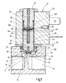
Fig. 1 im Längsschnitt dargestellte Vorrichtung zur Regelung eines fluiden oder gasförmigen Mediums weist ein 2/2-Wegeventil 11 und einen Elektromagneten 12 zur Betätigung des 2/2-Wegeventils 11 auf. Das 2/2-Wegeventil 11 besitzt ein Ventilgehäuse 13 mit einem Ventileinlass 14 und einem Ventilauslass 15, die über eine Ventilkammer 16 miteinander in Verbindung stehen. In der Ventilkammer 16 ist eine Ventilöffnung 17 ausgebildet, die von einem Ventilsitz 18 umschlossen ist, der zur Durchflussregelung des Mediums mit einem Ventilglied 19 zusammenwirkt, das durch mehr oder weniger weites Abheben vom Ventilsitz 18 die über die Ventilöffnung 17 strömende Durchflussmenge bestimmt. Die Steuerung des Ventilglieds 19 wird mittels des Elektromagneten 12 bewirkt, der vorzugsweise ein Proportionalverhalten aufweist. - Der Elektromagnet 12 besitzt eine Ankerhülse 20, in der ein Ankerstopfen 21 angeordnet und ein dem Ankerstopfen 21 axial gegenüberliegender Anker 22 axial verschieblich aufgenommen ist. Ankerhülse 20 und Ankerstopfen 21 können einstückig miteinander ausgeführt sein. Die Ankerhülse 20 ist von einer Erregerwicklung oder Magnetspule 23 umschlossen, die an der Ankerhülse 20 axial unverschieblich festgelegt ist. Die einander zukehrten Enden von Anker 22 und Ankerstopfen 21 sind konisch ausgebildet und greifen ineinander, wodurch die zwischen Anker 22 und Ankerstopfen 21 wirkende Magnetkraft unabhängig vom Hub des Ankers 22 ist.
- Die Ankerhülse 20 taucht mit einem Endabschnitt 201 in eine im Ventilgehäuse 13 eingebrachte, durchmessergestufte Ausnehmung 24 ein, deren durchmesserkleinerer, unterer Bereich die Ventilkammer 16 bildet. Der Endabschnitt 201 liegt in dem durchmessergrößeren, oberen Bereich der Ausnehmung 24 und stützt sich auf einer durch die Durchmesserstufung in der Ausnehmung 24 gebildeten Ringschulter 241 ab. Der Endabschnitt 201 der Ankerhülse 20 ist gegenüber der Ausnehmung 24 mittels eines Dichtungsrings 25 abgedichtet. Die Ankerhülse 20 ist am Ventilgehäuse 13 mittels eines über die Ankerhülse 20 geschobenen Befestigungsrings 26 befestigt, der den Dichtungsring 25 radial übergreift und diesen an eine am Endabschnitt 201 ausgebildete, äußere Ringschulter anpresst. Der Befestigungsring 26 ist am Ventilgehäuse 13, z.B. durch Schweißen, Verschrauben od. dgl., festgelegt.
- Der Anker 22 ist mittels zweier Flachfedern 27, 28 in der Ankerhülse 20 so gehalten, dass er mit minimalem Radialspiel berührungslos in der Ankerhülse 20 einliegt und axial verschiebbar ist, ohne dabei die Innenwand der Ankerhülse 20 zu berühren. Die eine Flachfeder 27 ist am oberen Stirnende und die andere Flachfeder 28 am unteren Stirnende des Ankers 22 angeordnet. Am unteren Stirnende des Ankers 22 ist das Ventilglied 19 befestigt. Das Ventilglied 19 weist einen Dichtungshalter 30 mit einem daran einstückig angeformten Zapfen 301 und eine in dem Dichtungshalter 30 aufgenommene Dichtplatte 31 auf, die mit dem Ventilsitz 18 zusammenwirkt. Zur Reduzierung der Fertigungskosten ist der Dichtungshalter 30 mit seinem Zapfen 301 in ein in die Stirnseite des Ankers 22 eingebrachtes Sackloch 32 eingepresst. An der Stirnseite des Ankers 22 ist ein zum Sackloch 32 konzentrischer Bund 33 angeformt, der als Kegelstumpf ausgeführt ist, der sich zum freien Ende hin verjüngt. Zwischen dem Bund 33 und dem Dichtungshalter 30 ist die eine Flachfeder 28 eingeklemmt.
- Die Dichtheit zwischen der Dichtplatte 31 und dem Ventilsitz 18 im Schließzustand des Ventils 11 wird durch eine Ventilschließfeder 29 herbeigeführt. Die Ventilschließfeder 29 ist in ein Sackloch 35 eingesetzt, das von dem dem Ankerstopfen 21 zugekehrten Stirnende des Ankers 22 aus in den Anker 22 eingebracht ist. Die als Schraubendruckfeder ausgebildete Ventilschließfeder 29 stützt sich einerseits am Lochgrund des Sacklochs 35 und andererseits an einem Justierstift 36 einer Justiereinrichtung zum Einstellen der Vorspannkraft der Ventilschließfeder 29 ab. Am Stirnende des Justierstiftes 36 ist ein axial vorstehender Führungszapfen 361 ausgebildet, der von einer radialen Auflageschulter 362 ringförmig umgeben ist. Auf den Führungszapfen 361 ist eine Zentrierhülse 37 aufgeschoben, die mit einem Flansch 371 an der Auflageschulter 362 anliegt. Das dem Justierstift 36 zugekehrte Ende der Ventilschließfeder 29 ist auf der Zentrierhülse 37 geführt und stützt sich an dem Flansch 371, diesen gegen die Auflageschulter 362 pressend, ab. Der Justierstift 36 ist im Ankerstopfen 21 verschraubbar, so dass durch Drehen des Justierstiftes 36 die Ventilschließfeder 29 mehr oder weniger komprimiert werden kann. Der Justierstift 36 tritt mit seinem aus dem Verschlussstopfen 21 herausragenden, freien Ende durch einen Niederhalter 38 hindurch, der in eine in der Stirnseite des Ankers 22 eingebrachte, konzentrische Ausnehmung 39 eintaucht und dort auf einer in der Ausnehmung 39 ausgebildeten Ringschulter 391 aufliegt.
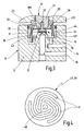
- Die obere und untere Flachfeder 27, 28 sind mit unterschiedlichem Durchmesser gleichartig ausgebildet. Ein Ausführungsbeispiel der Flachfedern 27, 28 ist in
Fig. 4 in Draufsicht dargestellt. Jede Flachfeder 27, 28 ist beispielsweise aus Federblech mit einer Materialstärke von 0,05 - 0,3 mm gefertigt und mit einer Zentralöffnung 40 versehen. Des weiteren sind in der Flachfeder 27 bzw. 28 spiralartig verlaufende Aussparungen 41 mit unterschiedlichem Radialabstand eingearbeitet. Die Flachfeder 27 weist einen kleineren Durchmesser als die Flachfeder 28 auf und ist in die Ausnehmung 39 im Anker 22 formschlüssig eingelegt, so dass sie keine radiale Relativbewegung zum Anker 22 ausführen kann. Ihr äußerer Randbereich liegt auf der in der Ausnehmung 39 ausgebildeten Ringschulter 391 auf und wird von dem Niederhalter 38 festgespannt. In der Zentralöffnung 40 liegt formschlüssig der Flansch 371 der Zentrierhülse 37 ein und zentriert die Flachfeder 27 am Justierstift 36. Die durchmessergrößere, untere Flachfeder 28 ist in die Ausnehmung 24 im Ventilgehäuse 13 formschlüssig eingelegt und liegt mit ihrem äußeren Randbereich auf der Ringschulter 241 der Ausnehmung 24 auf und wird durch die Ankerhülse 20 auf der Ringschulter 241 festgespannt. Die Flachfeder 28 ist mit ihrer Zentralöffnung 40 auf dem konisch ausgeführten Bund 33 aufgesetzt und von dem Dichtungshalter 30 gegen Abziehen gesichert, so dass die Flachfeder 28 auf der Mantelfläche des Bundes 33 zentriert ist. In einer alternativen Ausführung kann der die Zentralöffnung 40 umgebende Randbereich der Flachfeder 28 auf der ringförmigen Stirnfläche des Bundes 33 aufliegen, und der Zapfen 301 des Dichtungshalters 30 formschlüssig durch die Zentralöffnung 40 hindurchtreten, so dass die Flachfeder 28 einerseits am Zapfen 301 des Dichtungshalters 30 zentriert ist und andererseits zwischen dem Anker 22 und dem Dichtungshalter 30 festgespannt ist. - In dem in
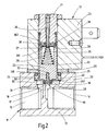
Fig. 2 dargestellten Ausführungsbeispiel ist die Regelungsvorrichtung insoweit modifiziert, als dass das in den Anker 22 eingebrachte Sackloch 35 zur Aufnahme der Ventilschließfeder 29 mit einem wesentlich größeren Durchmesser ausgeführt ist und zugleich die Ausnehmung 39 zur Aufnahme der oberen Flachfeder 27 und des Niederhalters 38 bildet. Das Sackloch 35 verjüngt sich zumindest im Bereich der Ausnehmung 39 in Richtung Lochgrund. In diesem konischen Bereich liegt der Niederhalter 38 und die sich mit ihrem äußeren Randbereich an einem Ringbund an der Unterseite des Niederhalters 38 abstützende Flachfeder 27 formschlüssig ein. Die Flachfeder 27 liegt mit ihrem die Zentralöffnung 40 umschließenden, inneren Randbereich an der Auflageschulter 362 des Justierstiftes 36 an und wird von dem Führungszapfen 361 des Justierstiftes 36 zentriert. Die Ventilschließfeder 39 ist als Konusfeder ausgebildet, die sich nach unten erweitert und sich über die obere Flachfeder 27 an der Auflageschulter 362 am Justierstift 36 abstützt. Durch diese konstruktiven Maßnahmen wirkt die Verstelleinrichtung zum Einstellen der Vorspannung der Ventilschließfeder 29 auch auf die obere Flachfeder 27 und verändert deren axiale Vorspannkraft mit. Durch die Konusform der Ventilschließfeder 29 wird Reibung zwischen der Ventilschließfeder 29 und der Lochwand des Sacklochs 35 vermieden. - Des weiteren ist in der Regelungsvorrichtung gemäß
Fig. 2 noch eine Verstelleinrichtung zur Verstellung des Ankerhubs vorgesehen. Diese besteht im einfachsten Fall aus einem Schraubgewinde 42 zwischen der im Ventilgehäuse 13 vorhandenen Ausnehmung 24 und dem Endabschnitt 201 der Ankerhülse 20. Die Ankerhülse 20 kann sich durch Drehen in der Ausnehmung 24 axial verschieben, so dass der Abstand zwischen dem Ankerstopfen 21 einerseits und dem Anker 22 bzw. dem vorzugsweise aus nichtmagnetischem Material bestehenden Niederhalter 38 andererseits und damit der Hub des Ankers 22 verändert werden kann. - Bei dem in
Fig. 3 ausschnittweise dargestellten Ausführungsbeispiel ist die Regelungsvorrichtung insofern modifiziert, als noch zusätzlich eine Verstelleinrichtung zur Verstellung der axialen Vorspannung der unteren Flachfeder 28 vorgesehen ist. Die Ankerhülse 20 ist wiederum mit ihrem Endabschnitt 201 in die im Ventilgehäuse 13 vorhandene Ausnehmung 24 dicht eingesetzt, ist aber in der Ausnehmung 24 um ihre Hülsenachse drehbar angeordnet. In dem Endabschnitt 201 der Ankerhülse 20 ist eine Aufnahmehülse 43 mittels eines Gewindes 44 verschraubbar. In der Aufnahmehülse 43 ist eine radiale Ringschulter 431 ausgebildet, auf der die untere Flachfeder 28 mit ihrem äußeren Randbereich aufliegt. Die Flachfeder 28 ist hier über ihre Zentralöffnung 40 mittels des Zapfens 301 des Dichtungshalters 30 am Anker 22 zentriert und mit ihrem die Zentralöffnung 40 umschließenden Randbereich zwischen dem Dichtungshalter 30 und der ringförmigen Stirnfläche des Bundes 33 am Anker 22 eingespannt. Wird die Ankerhülse 20 nunmehr so gedreht, dass sich die Aufnahmehülse 43, die in der Ausnehmung 39 undrehbar gehalten ist, durch das Gewinde 44 nach unten schraubt, so wird der äußere Rand der unteren Flachfeder 28 durch die Ringschulter 431 an der Aufnahmehülse 43 nach unten gedrückt, so dass sich die axiale Vorspannkraft der unteren Flachfeder 28 vergrößert. Eine geeignet gerichtete Vorspannung der Flachfedern 27, 28 kann zur Unterstützung des Öffnungshubs oder zur Erhöhung der Dichtschließkraft des Ventilglieds 19 herangezogen werden.
Claims (9)
- Vorrichtung zur Regelung eines fluiden oder gasförmigen Mediums, mit einem Ventilgehäuse (13), das einen Ventilein- und -auslass (14, 15) aufweist, die über eine von einem Ventilsitz (18) umschlossene Ventilöffnung (17) miteinander in Verbindung stehen, mit einem mit dem Ventilsitz (18) zur Durchflussregelung des Mediums durch die Ventilöffnung (17) zusammenwirkenden Ventilglied (19) und mit einem Elektromagneten (12), der einen mit dem Ventilglied (19) verbundenen Anker (22), eine den Anker (22) und einen Ankerstopfen (21) aufnehmende Ankerhülse (20) und eine die Ankerhülse (20) umschließende Magnetspule (23) aufweist, wobei der Anker (22) über mindestens zwei Federn so gehalten ist, dass er in der Ankerhülse (20) berührungslos axial verschiebbar einliegt und eine Feder zum Aufsetzen des Ventilglieds (19) auf den Ventilsitz (18) dient,
dadurch gekennzeichnet,
dass am Anker (22) eine vorgespannte Ventilschließfeder (29) zum Aufsetzen des Ventilglieds (19) auf den Ventilsitz (18) angreift, dass am Anker (22) mindestens zwei Flachfedern (27, 28), von denen mindestens eine Flachfeder (27) an einem Stirnende und mindestens eine andere Flachfeder (28) am anderen Stirnende des Ankers (22) angeordnet ist, angreifen und dass jeder Flachfeder (27, 28) eine Einstellvorrichtung zur Einstellung der axialen Federvorspannung zugeordnet ist. - Vorrichtung nach Anspruch 1, dadurch gekennzeichnet, dass die Ventilschließfeder (29) in einem in den Anker (22) eingebrachten, zentralen Sackloch (35) einliegt und sich einerseits am Sacklochboden und andererseits an einer Auflageschulter (362) abstützt, die an einem im Ankerstopfen (21) verschraubbaren Justierstift (36) einer Justiereinrichtung zur Einstellung der Vorspannkraft der Ventilschließfeder (29) ausgebildet ist, und dass ein vom Justierstift (36) abstehender, von der Auflageschulter (362) umgebener Führungszapfen (361) in die vorzugsweise als konisch sich zum Sacklochboden hin aufweitende Schraubendruckfeder ausgebildete Ventilschließfeder (29) eintaucht.
- Vorrichtung nach einem der Ansprüche 1 oder 2, dadurch gekennzeichnet, dass mindestens eine Flachfeder (27) in einer in die dem Ankerstopfen (21) zugekehrte Stirnseite des Ankers (22) eingebrachten, konzentrischen Ausnehmung (39) formschlüssig einliegt und am Justierstift (36) zentriert ist.
- Vorrichtung nach einem der Ansprüche 1 bis 3, dadurch gekennzeichnet, dass mindestens eine Flachfeder (27) randseitig auf einer in der Ausnehmung (39) ausgebildeten Ringschulter (391) aufliegt und auf der Ringschulter (391) mittels eines in die Ausnehmung (39) eingesetzten Niederhalters (38) festgespannt ist, durch den der Justierstift (36) hindurchgeführt ist.
- Vorrichtung nach einem der Ansprüche 1 bis 4, dadurch gekennzeichnet, dass mindestens eine Flachfeder (27) eine Zentralöffnung (40) aufweist, die von dem Führungszapfen (361) des Justierstiftes (36) oder einer auf den Führungszapfen (361) aufgeschobenen Zentrierhülse (37) formschlüssig durchsetzt ist, und dass die Flachfeder (27) mit ihrem die Zentralöffnung (40) umgebenden Randbereich auf der Auflageschulter (362) des Justierstiftes (36) und/oder an dem Niederhalter (38) anliegt.
- Vorrichtung nach einem der Ansprüche 1 bis 5, dadurch gekennzeichnet, dass mindestens eine Flachfeder (28) in einer im Ventilgehäuse (13) konzentrisch zum Ventilsitz (18) angeordneten Aufnahme formschlüssig einliegt und auf der in die Aufnahme eintauchenden Stirnseite des Ankers (22) zentriert ist und vorzugsweise zwischen dem am Anker (22) befestigten Ventilglied (19) und dem Anker (22) eingespannt ist.
- Vorrichtung nach Anspruch 6, dadurch gekennzeichnet, dass in der Aufnahme eine radial vorstehende Ringschulter (241; 431) ausgebildet ist, auf der die Flachfeder (28) mit ihrem äußeren Randbereich aufliegt.
- Vorrichtung nach Anspruch 7, dadurch gekennzeichnet, dass die Aufnahme von einer in das Ventilgehäuse (13) eingebrachten Ausnehmung (24) gebildet ist und dass die Flachfeder (28) auf der Ringschulter (241) mittels der mit einem Endabschnitt (201) in die Ausnehmung (24) eintauchenden Ankerhülse (20) festgespannt ist.
- Vorrichtung nach Anspruch 7, dadurch gekennzeichnet, dass die Ankerhülse (20) mit einem Endabschnitt (201) drehbar in eine im Ventilgehäuse (13) ausgebildete Ausnehmung (24) eintaucht und dass die Aufnahme mit Ringschulter (431) von einer in dem Endabschnitt (201) der Ankerhülse (20) verschraubbaren, im Ventilgehäuse (13) undrehbar gehaltenen Aufnahmehülse (43) gebildet ist.
Priority Applications (2)
| Application Number | Priority Date | Filing Date | Title |
|---|---|---|---|
| EP20030027541 EP1536169B1 (de) | 2003-11-29 | 2003-11-29 | Elektromagnetisches Ventil |
| DE50310748T DE50310748D1 (de) | 2003-11-29 | 2003-11-29 | Elektromagnetisches Ventil |
Applications Claiming Priority (1)
| Application Number | Priority Date | Filing Date | Title |
|---|---|---|---|
| EP20030027541 EP1536169B1 (de) | 2003-11-29 | 2003-11-29 | Elektromagnetisches Ventil |
Publications (2)
| Publication Number | Publication Date |
|---|---|
| EP1536169A1 EP1536169A1 (de) | 2005-06-01 |
| EP1536169B1 true EP1536169B1 (de) | 2008-11-05 |
Family
ID=34442917
Family Applications (1)
| Application Number | Title | Priority Date | Filing Date |
|---|---|---|---|
| EP20030027541 Expired - Lifetime EP1536169B1 (de) | 2003-11-29 | 2003-11-29 | Elektromagnetisches Ventil |
Country Status (2)
| Country | Link |
|---|---|
| EP (1) | EP1536169B1 (de) |
| DE (1) | DE50310748D1 (de) |
Cited By (19)
| Publication number | Priority date | Publication date | Assignee | Title |
|---|---|---|---|---|
| CN102996792A (zh) * | 2012-12-24 | 2013-03-27 | 北京七星华创电子股份有限公司 | 一种金属密封圈 |
| EP2682655A2 (de) | 2012-07-05 | 2014-01-08 | Asco Joucomatic SA | Magnetventil mit flachem Kern und flacher Feder |
| US8839815B2 (en) | 2011-12-15 | 2014-09-23 | Honeywell International Inc. | Gas valve with electronic cycle counter |
| US8899264B2 (en) | 2011-12-15 | 2014-12-02 | Honeywell International Inc. | Gas valve with electronic proof of closure system |
| US8905063B2 (en) | 2011-12-15 | 2014-12-09 | Honeywell International Inc. | Gas valve with fuel rate monitor |
| US8947242B2 (en) | 2011-12-15 | 2015-02-03 | Honeywell International Inc. | Gas valve with valve leakage test |
| EP2853792A1 (de) | 2013-09-26 | 2015-04-01 | Asco Numatics GmbH | Vorrichtung zur Durchflussregelung eines Fluids |
| US9074770B2 (en) | 2011-12-15 | 2015-07-07 | Honeywell International Inc. | Gas valve with electronic valve proving system |
| CN105179540A (zh) * | 2015-08-25 | 2015-12-23 | 同济大学 | 扇形弹簧臂及其组成的片弹簧和采用该片弹簧的压缩机 |
| US9234661B2 (en) | 2012-09-15 | 2016-01-12 | Honeywell International Inc. | Burner control system |
| US9557059B2 (en) | 2011-12-15 | 2017-01-31 | Honeywell International Inc | Gas valve with communication link |
| US9995486B2 (en) | 2011-12-15 | 2018-06-12 | Honeywell International Inc. | Gas valve with high/low gas pressure detection |
| US10024439B2 (en) | 2013-12-16 | 2018-07-17 | Honeywell International Inc. | Valve over-travel mechanism |
| US10203049B2 (en) | 2014-09-17 | 2019-02-12 | Honeywell International Inc. | Gas valve with electronic health monitoring |
| US10215291B2 (en) | 2013-10-29 | 2019-02-26 | Honeywell International Inc. | Regulating device |
| US10564062B2 (en) | 2016-10-19 | 2020-02-18 | Honeywell International Inc. | Human-machine interface for gas valve |
| US10697815B2 (en) | 2018-06-09 | 2020-06-30 | Honeywell International Inc. | System and methods for mitigating condensation in a sensor module |
| US10851993B2 (en) | 2011-12-15 | 2020-12-01 | Honeywell International Inc. | Gas valve with overpressure diagnostics |
| US11073281B2 (en) | 2017-12-29 | 2021-07-27 | Honeywell International Inc. | Closed-loop programming and control of a combustion appliance |
Families Citing this family (25)
| Publication number | Priority date | Publication date | Assignee | Title |
|---|---|---|---|---|
| EP1970610B1 (de) * | 2007-03-14 | 2010-05-26 | Asco Joucomatic GmbH | Vorrichtung zur Regelung eines fluiden oder gasförmigen Mediums |
| DE102007047422B4 (de) | 2007-10-04 | 2024-06-20 | Robert Bosch Gmbh | Elektromagnetisches Druckventil |
| SE531814C2 (sv) * | 2007-10-17 | 2009-08-11 | Oehlins Racing Ab | Ventil med fjäderarrangemang för justering av en stötdämpares dämpmedieflöde |
| EP2068056B1 (de) | 2007-12-08 | 2010-08-04 | Asco Joucomatic GmbH | Vorrichtung zur Durchflussregelung eines flüssigen oder gasförmigen Mediums |
| DE102009022538A1 (de) | 2009-05-25 | 2010-12-02 | Svm Schultz Verwaltungs-Gmbh & Co. Kg | Elektromagnet mit einem mediengefüllten Ankerraum |
| FR2955908B1 (fr) | 2010-02-02 | 2012-05-04 | Asco Joucomatic Sa | Electrovanne pilote |
| DE102010002224A1 (de) * | 2010-02-23 | 2011-08-25 | Robert Bosch GmbH, 70469 | Magnetventil zum Steuern eines Fluids |
| EP2365239B1 (de) | 2010-03-12 | 2015-03-04 | Asco Numatics GmbH | Vorrichtung zur Durchflussregelung eines flüssigen oder gasförmigen Mediums |
| DE102010030299A1 (de) * | 2010-06-21 | 2011-12-22 | Krones Aktiengesellschaft | Vorrichtung zum Antreiben eines Doppelsitzventils |
| EP2400193B1 (de) * | 2010-06-23 | 2019-08-28 | Asco Numatics GmbH | Vorrichtung zur Durchflussregelung eines flüssigen oder gasförmigen Mediums |
| DE202010010279U1 (de) | 2010-07-15 | 2010-11-18 | Bürkert Werke GmbH | Magnetventil |
| EP2600360B1 (de) * | 2011-12-01 | 2017-04-12 | SVM Schultz Verwaltungs-GmbH & Co. KG | Elektromagnet |
| US9846440B2 (en) | 2011-12-15 | 2017-12-19 | Honeywell International Inc. | Valve controller configured to estimate fuel comsumption |
| US9835265B2 (en) | 2011-12-15 | 2017-12-05 | Honeywell International Inc. | Valve with actuator diagnostics |
| CN103185167B (zh) * | 2011-12-30 | 2016-03-02 | 北京谊安医疗系统股份有限公司 | 板式弹簧组件 |
| CN103629415B (zh) * | 2012-08-23 | 2016-03-02 | 丹佛斯(天津)有限公司 | 动铁芯组件及使用其的电磁阀 |
| US10422531B2 (en) | 2012-09-15 | 2019-09-24 | Honeywell International Inc. | System and approach for controlling a combustion chamber |
| US9841122B2 (en) | 2014-09-09 | 2017-12-12 | Honeywell International Inc. | Gas valve with electronic valve proving system |
| US10088068B2 (en) * | 2015-09-23 | 2018-10-02 | Hamilton Sundstrand Corporation | Flexures for flow regulation devices |
| US10503181B2 (en) | 2016-01-13 | 2019-12-10 | Honeywell International Inc. | Pressure regulator |
| JP6416159B2 (ja) * | 2016-07-25 | 2018-10-31 | Ckd株式会社 | 電磁アクチュエータ |
| JP6909077B2 (ja) * | 2017-07-05 | 2021-07-28 | 日立Astemo株式会社 | 緩衝器 |
| CN111692398B (zh) * | 2020-05-19 | 2021-05-07 | 徐州华宝能源科技有限公司 | 一种天然气站开关安全保护装置 |
| CN114763855B (zh) * | 2021-01-13 | 2025-08-19 | 浙江三花智能控制股份有限公司 | 一种比例调节装置及具有该比例调节装置的燃气阀 |
| CN114623243B (zh) * | 2022-03-15 | 2024-06-04 | 一汽解放汽车有限公司 | 用于燃料电池的喷射阀 |
Family Cites Families (4)
| Publication number | Priority date | Publication date | Assignee | Title |
|---|---|---|---|---|
| GB2189010B (en) * | 1986-03-07 | 1990-03-21 | Alexander Controls Ltd | Apparatus for controlling the flow of gas |
| KR100723859B1 (ko) * | 1999-11-16 | 2007-05-31 | 콘티넨탈 테베스 아게 운트 코. 오하게 | 전자석 밸브 |
| DE10039066A1 (de) | 2000-08-10 | 2002-02-21 | Asco Joucomatic Gmbh & Co | Ventil zur Regelung eines fluiden oder gasförmigen Mediums |
| JP2002295711A (ja) * | 2001-04-02 | 2002-10-09 | Aisan Ind Co Ltd | 高圧開閉弁装置 |
-
2003
- 2003-11-29 DE DE50310748T patent/DE50310748D1/de not_active Expired - Lifetime
- 2003-11-29 EP EP20030027541 patent/EP1536169B1/de not_active Expired - Lifetime
Cited By (21)
| Publication number | Priority date | Publication date | Assignee | Title |
|---|---|---|---|---|
| US9557059B2 (en) | 2011-12-15 | 2017-01-31 | Honeywell International Inc | Gas valve with communication link |
| US8839815B2 (en) | 2011-12-15 | 2014-09-23 | Honeywell International Inc. | Gas valve with electronic cycle counter |
| US8899264B2 (en) | 2011-12-15 | 2014-12-02 | Honeywell International Inc. | Gas valve with electronic proof of closure system |
| US8905063B2 (en) | 2011-12-15 | 2014-12-09 | Honeywell International Inc. | Gas valve with fuel rate monitor |
| US8947242B2 (en) | 2011-12-15 | 2015-02-03 | Honeywell International Inc. | Gas valve with valve leakage test |
| US10851993B2 (en) | 2011-12-15 | 2020-12-01 | Honeywell International Inc. | Gas valve with overpressure diagnostics |
| US9074770B2 (en) | 2011-12-15 | 2015-07-07 | Honeywell International Inc. | Gas valve with electronic valve proving system |
| US10697632B2 (en) | 2011-12-15 | 2020-06-30 | Honeywell International Inc. | Gas valve with communication link |
| US9995486B2 (en) | 2011-12-15 | 2018-06-12 | Honeywell International Inc. | Gas valve with high/low gas pressure detection |
| EP2682655A2 (de) | 2012-07-05 | 2014-01-08 | Asco Joucomatic SA | Magnetventil mit flachem Kern und flacher Feder |
| US9234661B2 (en) | 2012-09-15 | 2016-01-12 | Honeywell International Inc. | Burner control system |
| CN102996792A (zh) * | 2012-12-24 | 2013-03-27 | 北京七星华创电子股份有限公司 | 一种金属密封圈 |
| CN102996792B (zh) * | 2012-12-24 | 2015-11-25 | 北京七星华创电子股份有限公司 | 一种金属密封圈 |
| EP2853792A1 (de) | 2013-09-26 | 2015-04-01 | Asco Numatics GmbH | Vorrichtung zur Durchflussregelung eines Fluids |
| US10215291B2 (en) | 2013-10-29 | 2019-02-26 | Honeywell International Inc. | Regulating device |
| US10024439B2 (en) | 2013-12-16 | 2018-07-17 | Honeywell International Inc. | Valve over-travel mechanism |
| US10203049B2 (en) | 2014-09-17 | 2019-02-12 | Honeywell International Inc. | Gas valve with electronic health monitoring |
| CN105179540A (zh) * | 2015-08-25 | 2015-12-23 | 同济大学 | 扇形弹簧臂及其组成的片弹簧和采用该片弹簧的压缩机 |
| US10564062B2 (en) | 2016-10-19 | 2020-02-18 | Honeywell International Inc. | Human-machine interface for gas valve |
| US11073281B2 (en) | 2017-12-29 | 2021-07-27 | Honeywell International Inc. | Closed-loop programming and control of a combustion appliance |
| US10697815B2 (en) | 2018-06-09 | 2020-06-30 | Honeywell International Inc. | System and methods for mitigating condensation in a sensor module |
Also Published As
| Publication number | Publication date |
|---|---|
| DE50310748D1 (de) | 2008-12-18 |
| EP1536169A1 (de) | 2005-06-01 |
Similar Documents
| Publication | Publication Date | Title |
|---|---|---|
| EP1536169B1 (de) | Elektromagnetisches Ventil | |
| EP2400193B1 (de) | Vorrichtung zur Durchflussregelung eines flüssigen oder gasförmigen Mediums | |
| DE3802648C2 (de) | ||
| EP0615498B1 (de) | Magnetventil | |
| DE69103563T2 (de) | Elektromagnetisch betätigte Kraftstoffeinspritzvorrichtung für eine Brennkraftmaschine. | |
| DE2843514C2 (de) | ||
| DE3107775C2 (de) | ||
| DE69101897T2 (de) | Steuerventil und Anker für ein elektromagnetisches Brennstoffeinspritzventil für Verbrennungsmotoren. | |
| EP2246601B1 (de) | Elektromagnetisches Hydraulikventil | |
| EP2906815B1 (de) | Ventil für eine pumpe | |
| DE102018105348B4 (de) | Magnetventil | |
| EP1970610A1 (de) | Vorrichtung zur Regelung eines fluiden oder gasförmigen Mediums | |
| DE3335169C2 (de) | Kraftstoffeinspritzvorrichtung | |
| EP2156046A1 (de) | Ankerhubeinstellung für magnetventil | |
| EP2558757A1 (de) | Stromregelventil | |
| DE4428385B4 (de) | Ventilkörper | |
| EP2853792B2 (de) | Vorrichtung zur Durchflussregelung eines Fluids | |
| DE1143108B (de) | Hydraulik-Stossdaempfer fuer Steuerregler von Fluessigkeitsverteilern zum Aufrechterhalten der Hoehenlage eines Fahrzeugaufbaues oder -rahmens | |
| DE2657197C2 (de) | ||
| DE1961248A1 (de) | Ventil | |
| DE19625349A1 (de) | Magnetbetätigtes Sitzventil | |
| DE19852409A1 (de) | Druckbegrenzungsventil, insbesondere für Fahrzeuge | |
| DE4022395C2 (de) | Proportionalmagnetventil und Verfahren zur Montage eines solchen Proportionalmagnetventiles | |
| DE3016543A1 (de) | Kraftstoffeinspritzanlage | |
| EP0684418B1 (de) | Elektromagnetventil |
Legal Events
| Date | Code | Title | Description |
|---|---|---|---|
| PUAI | Public reference made under article 153(3) epc to a published international application that has entered the european phase |
Free format text: ORIGINAL CODE: 0009012 |
|
| AK | Designated contracting states |
Kind code of ref document: A1 Designated state(s): AT BE BG CH CY CZ DE DK EE ES FI FR GB GR HU IE IT LI LU MC NL PT RO SE SI SK TR |
|
| AX | Request for extension of the european patent |
Extension state: AL LT LV MK |
|
| 17P | Request for examination filed |
Effective date: 20051005 |
|
| TPAC | Observations filed by third parties |
Free format text: ORIGINAL CODE: EPIDOSNTIPA |
|
| AKX | Designation fees paid |
Designated state(s): CH DE FR GB LI |
|
| GRAP | Despatch of communication of intention to grant a patent |
Free format text: ORIGINAL CODE: EPIDOSNIGR1 |
|
| GRAS | Grant fee paid |
Free format text: ORIGINAL CODE: EPIDOSNIGR3 |
|
| GRAA | (expected) grant |
Free format text: ORIGINAL CODE: 0009210 |
|
| AK | Designated contracting states |
Kind code of ref document: B1 Designated state(s): CH DE FR GB LI |
|
| REG | Reference to a national code |
Ref country code: GB Ref legal event code: FG4D Free format text: NOT ENGLISH |
|
| REG | Reference to a national code |
Ref country code: CH Ref legal event code: EP |
|
| REG | Reference to a national code |
Ref country code: CH Ref legal event code: NV Representative=s name: PATENTANWALTSBUERO JEAN HUNZIKER AG |
|
| REF | Corresponds to: |
Ref document number: 50310748 Country of ref document: DE Date of ref document: 20081218 Kind code of ref document: P |
|
| PLBE | No opposition filed within time limit |
Free format text: ORIGINAL CODE: 0009261 |
|
| STAA | Information on the status of an ep patent application or granted ep patent |
Free format text: STATUS: NO OPPOSITION FILED WITHIN TIME LIMIT |
|
| 26N | No opposition filed |
Effective date: 20090806 |
|
| REG | Reference to a national code |
Ref country code: DE Ref legal event code: R082 Ref document number: 50310748 Country of ref document: DE Representative=s name: KRATZSCH UND KOLLEGEN, DE |
|
| REG | Reference to a national code |
Ref country code: DE Ref legal event code: R082 Ref document number: 50310748 Country of ref document: DE Representative=s name: WITTE, WELLER & PARTNER, DE Effective date: 20110822 Ref country code: DE Ref legal event code: R081 Ref document number: 50310748 Country of ref document: DE Owner name: ASCO NUMATICS GMBH, DE Free format text: FORMER OWNER: ASCO JOUCOMATIC GMBH, 75248 OELBRONN-DUERRN, DE Effective date: 20110822 Ref country code: DE Ref legal event code: R082 Ref document number: 50310748 Country of ref document: DE Representative=s name: WITTE, WELLER & PARTNER PATENTANWAELTE MBB, DE Effective date: 20110822 |
|
| REG | Reference to a national code |
Ref country code: DE Ref legal event code: R082 Ref document number: 50310748 Country of ref document: DE Representative=s name: WITTE, WELLER & PARTNER, DE Ref country code: DE Ref legal event code: R082 Ref document number: 50310748 Country of ref document: DE Representative=s name: WITTE, WELLER & PARTNER PATENTANWAELTE MBB, DE |
|
| REG | Reference to a national code |
Ref country code: CH Ref legal event code: PUE Owner name: ASCO NUMATICS GMBH, DE Free format text: FORMER OWNER: ASCO JOUCOMATIC GMBH, DE |
|
| REG | Reference to a national code |
Ref country code: FR Ref legal event code: CD Owner name: ASCO NUMATICS GMBH, DE Effective date: 20141023 |
|
| REG | Reference to a national code |
Ref country code: FR Ref legal event code: PLFP Year of fee payment: 13 |
|
| REG | Reference to a national code |
Ref country code: FR Ref legal event code: PLFP Year of fee payment: 14 |
|
| REG | Reference to a national code |
Ref country code: FR Ref legal event code: PLFP Year of fee payment: 15 |
|
| PGFP | Annual fee paid to national office [announced via postgrant information from national office to epo] |
Ref country code: FR Payment date: 20171121 Year of fee payment: 15 |
|
| PGFP | Annual fee paid to national office [announced via postgrant information from national office to epo] |
Ref country code: CH Payment date: 20171120 Year of fee payment: 15 |
|
| REG | Reference to a national code |
Ref country code: CH Ref legal event code: PL |
|
| PG25 | Lapsed in a contracting state [announced via postgrant information from national office to epo] |
Ref country code: CH Free format text: LAPSE BECAUSE OF NON-PAYMENT OF DUE FEES Effective date: 20181130 Ref country code: LI Free format text: LAPSE BECAUSE OF NON-PAYMENT OF DUE FEES Effective date: 20181130 |
|
| PG25 | Lapsed in a contracting state [announced via postgrant information from national office to epo] |
Ref country code: FR Free format text: LAPSE BECAUSE OF NON-PAYMENT OF DUE FEES Effective date: 20181130 |
|
| PGFP | Annual fee paid to national office [announced via postgrant information from national office to epo] |
Ref country code: GB Payment date: 20221021 Year of fee payment: 20 Ref country code: DE Payment date: 20221020 Year of fee payment: 20 |
|
| REG | Reference to a national code |
Ref country code: DE Ref legal event code: R071 Ref document number: 50310748 Country of ref document: DE |
|
| REG | Reference to a national code |
Ref country code: GB Ref legal event code: PE20 Expiry date: 20231128 |
|
| PG25 | Lapsed in a contracting state [announced via postgrant information from national office to epo] |
Ref country code: GB Free format text: LAPSE BECAUSE OF EXPIRATION OF PROTECTION Effective date: 20231128 |
|
| PG25 | Lapsed in a contracting state [announced via postgrant information from national office to epo] |
Ref country code: GB Free format text: LAPSE BECAUSE OF EXPIRATION OF PROTECTION Effective date: 20231128 |