EP1536166A1 - Dichtung mit einem verdickten Blech - Google Patents
Dichtung mit einem verdickten Blech Download PDFInfo
- Publication number
- EP1536166A1 EP1536166A1 EP04027852A EP04027852A EP1536166A1 EP 1536166 A1 EP1536166 A1 EP 1536166A1 EP 04027852 A EP04027852 A EP 04027852A EP 04027852 A EP04027852 A EP 04027852A EP 1536166 A1 EP1536166 A1 EP 1536166A1
- Authority
- EP
- European Patent Office
- Prior art keywords
- sheet
- openings
- stops
- joint
- seal
- Prior art date
- Legal status (The legal status is an assumption and is not a legal conclusion. Google has not performed a legal analysis and makes no representation as to the accuracy of the status listed.)
- Granted
Links
- 239000002184 metal Substances 0.000 title abstract description 4
- 230000008719 thickening Effects 0.000 claims description 4
- 238000002485 combustion reaction Methods 0.000 description 6
- 239000012530 fluid Substances 0.000 description 4
- 239000011888 foil Substances 0.000 description 3
- 238000004080 punching Methods 0.000 description 3
- 230000006835 compression Effects 0.000 description 2
- 238000007906 compression Methods 0.000 description 2
- 238000001816 cooling Methods 0.000 description 2
- 125000006850 spacer group Chemical group 0.000 description 2
- 230000007547 defect Effects 0.000 description 1
- 238000010348 incorporation Methods 0.000 description 1
- 239000000463 material Substances 0.000 description 1
- 239000011159 matrix material Substances 0.000 description 1
- 238000000034 method Methods 0.000 description 1
Images

Classifications
-
- F—MECHANICAL ENGINEERING; LIGHTING; HEATING; WEAPONS; BLASTING
- F02—COMBUSTION ENGINES; HOT-GAS OR COMBUSTION-PRODUCT ENGINE PLANTS
- F02F—CYLINDERS, PISTONS OR CASINGS, FOR COMBUSTION ENGINES; ARRANGEMENTS OF SEALINGS IN COMBUSTION ENGINES
- F02F11/00—Arrangements of sealings in combustion engines
- F02F11/002—Arrangements of sealings in combustion engines involving cylinder heads
-
- F—MECHANICAL ENGINEERING; LIGHTING; HEATING; WEAPONS; BLASTING
- F16—ENGINEERING ELEMENTS AND UNITS; GENERAL MEASURES FOR PRODUCING AND MAINTAINING EFFECTIVE FUNCTIONING OF MACHINES OR INSTALLATIONS; THERMAL INSULATION IN GENERAL
- F16J—PISTONS; CYLINDERS; SEALINGS
- F16J15/00—Sealings
- F16J15/02—Sealings between relatively-stationary surfaces
- F16J15/06—Sealings between relatively-stationary surfaces with solid packing compressed between sealing surfaces
- F16J15/08—Sealings between relatively-stationary surfaces with solid packing compressed between sealing surfaces with exclusively metal packing
- F16J15/0818—Flat gaskets
- F16J15/0825—Flat gaskets laminated
-
- F—MECHANICAL ENGINEERING; LIGHTING; HEATING; WEAPONS; BLASTING
- F16—ENGINEERING ELEMENTS AND UNITS; GENERAL MEASURES FOR PRODUCING AND MAINTAINING EFFECTIVE FUNCTIONING OF MACHINES OR INSTALLATIONS; THERMAL INSULATION IN GENERAL
- F16J—PISTONS; CYLINDERS; SEALINGS
- F16J15/00—Sealings
- F16J15/02—Sealings between relatively-stationary surfaces
- F16J15/06—Sealings between relatively-stationary surfaces with solid packing compressed between sealing surfaces
- F16J15/08—Sealings between relatively-stationary surfaces with solid packing compressed between sealing surfaces with exclusively metal packing
- F16J15/0818—Flat gaskets
- F16J2015/085—Flat gaskets without fold over
-
- F—MECHANICAL ENGINEERING; LIGHTING; HEATING; WEAPONS; BLASTING
- F16—ENGINEERING ELEMENTS AND UNITS; GENERAL MEASURES FOR PRODUCING AND MAINTAINING EFFECTIVE FUNCTIONING OF MACHINES OR INSTALLATIONS; THERMAL INSULATION IN GENERAL
- F16J—PISTONS; CYLINDERS; SEALINGS
- F16J15/00—Sealings
- F16J15/02—Sealings between relatively-stationary surfaces
- F16J15/06—Sealings between relatively-stationary surfaces with solid packing compressed between sealing surfaces
- F16J15/08—Sealings between relatively-stationary surfaces with solid packing compressed between sealing surfaces with exclusively metal packing
- F16J15/0818—Flat gaskets
- F16J2015/0868—Aspects not related to the edges of the gasket
Definitions
- the present invention relates to a seal, in particular a cylinder head gasket, comprising a sheet with an extra thickness.
- a cylinder head gasket is used to seal between an engine block and a breech.
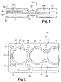
- a cylinder head gasket 10 generally the shape of the engine block, in particular rectangular, and comprises a plurality openings, to ensure continuity between cavities or ducts arranged on the one hand in the engine block, and on the other hand in the cylinder head.
- first openings 12 are provided for the chambers to combustion, second openings 14 for the conduits of the fluid or fluids of cooling and third openings 16 to allow the passage bolt fixing elements on the engine block, in particular rods threaded.
- the cylinder head gasket must ensure a good seal between ducted between them and between the ducts and the outside despite the defects of the surfaces in contact with the engine block and the cylinder head and the temperature variations.
- cylinder head 10 comprises several sheets or stacked sheets, in particular two sheets outer walls 18 between which is disposed an intermediate plate 20. At least one of the outer plates 18 has a rib 22 around the first openings 12, near said openings, oriented towards the inside of the joint, in order to obtain a deformable zone allowing to compensate for the deformations of the joint. So when ribs 22 are provided on the two outer plates 18, the projections of said ribs are arranged facing each other and oriented toward one another or opposition.
- said seal 10 comprises a shim 24 called stopper, arranged at the periphery of the first openings 12 provided for combustion chambers and edge to board with the intermediate plate 20.
- This stopper 24 has a thickness slightly greater than the thickness of the sheet insert 20 allowing on the one hand to obtain a higher clamping force around the combustion chambers, and on the other hand, to obtain a prestressing at least one of the outer plates 18 reducing the amplitude of deflection and crushing of the ribs.
- a stopper 24 causes constraints mechanical at the level of the outer plates 18 because of the bracing said outer sheets at the time of tightening. Moreover, the pressures of high contact generated at the stopper during tightening are transmitted also to the engine block and the cylinder head causing deformation the combustion chamber openings, which are likely to to lead to an increase in oil consumption and a noise level of high engine operation. This phenomenon is accentuated at the level of lateral ends of the joint, the clamping means in these areas spreading their efforts only on one opening and not on two openings for other clamping means.
- the extra thickness is obtained by bringing back on the surface of the intermediate sheet 20 a foil 26 or a thin sheet, less than or equal to 0.1 mm thick.
- the present invention aims at overcoming the disadvantages of the prior art in proposing a joint incorporating a sheet with at least one extra thickness to balance the constraints related to the presence of a stopper, said thickening being obtained from a simple process.
- FIGS. 3, 4A to 4C there is shown at 30 a plate suitable for incorporation into a cylinder head gasket sheets or sheets stacked, said seal being capable of being interposed between a engine block and a cylinder head.
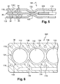
- FIGS. 5 and 6 there is shown by way of example a cylinder head gasket 100 incorporating a sheet metal 30 according to the invention as intermediate sheet.
- the elements common with the prior art have the same references increased from 100.
- a cylinder head gasket comprises a plurality of openings to ensure continuity between cavities or conduits in said engine block and said cylinder head.
- first openings 112 are provided for the chambers to combustion, second openings 114 for the conduits of the fluid or fluids cooling and third openings 116 to allow the passage bolt fixing elements on the engine block, in particular rods threaded.
- the head gasket also comprises at least one active outer sheet 118, and preferably two between which is disposed the intermediate plate 30.
- Au least one of the outer plates has a rib 122 around the first openings, near said openings, facing inwards of the joint, in order to obtain a deformable zone making it possible to compensate deformations of the joint.
- said seal comprises an excess thickness called stopper 124, arranged at the periphery of the apertures likely to coincide with the combustion chambers.
- the intermediate sheet 30 comprises localized zones of thickening 32, may preferably be arranged outside the ribs provided on the active outer plates.
- these areas of extra thickness are provided at the periphery of the joint, as well as around each opening.
- the zones of extra thickness 32 comprise a plurality of stops 34 obtained by plastic deformation of the intermediate plate 30, from protruding from at least one of the faces of said intermediate plate 30.
- stop means a plastic deformation forming a projecting element on one of the faces and a cavity on the other face, said cavity comprising a wall continuous lateral.
- a stop according to the invention can not return completely flat.
- This arrangement makes it possible to obtain, in a simple and economical manner, overthicknesses on a sheet, in particular an intermediate sheet.
- the stops 34 protrude on both sides of the sheet intermediate 30, preferably alternately.
- abutments may have sections of various shapes, including circular as illustrated in FIG. 3.
- the stops 34 could be open and bottomless and have only one wall each continuous lateral.
- the stops 34 can be arranged at the level of the surface or surfaces of different ways. Thus, the stops 34 can be aligned as illustrated in Figure 3.
- the density of stops 34 namely the number of stops per unit area, is adjusted according to the desired crush resistance, the latter being proportional to the density.
- Resistance to crushing means the ability of an element to oppose the variation of its thickness when it is subjected in particular to an effort of compression, the thickness corresponding to the dimensional value oriented according to the compression effort.
- the stops 34 are obtained by punching using one or more punches and a matrix without play.
- the stops 34 undergo a calibration operation, after that punching, to obtain a controlled height of exceedances of said stops 34.
- this overshoot is of the order of 0.4 mm.
- the stops according to the invention can be deformed during the clamping plastically and / or elastically in at least one direction substantially perpendicular to the plane of the sheet 30.
- This arrangement makes it possible to obtain an excess thickness 32, the thickness of which is adaptable on the one hand to clamping forces, and on the other hand to forms of the elements in contact with said overthickness.
- the abutments 34 may undergo a preforming operation to obtain a section a at the end of the abutments 34 greater than the section b at the base of said abutments 34. This feature makes it possible to limit the elasticity of the abutments 34, the plastically deformed abutment being unable to regain its initial profile as illustrated in FIG. 4A.
- Preforming makes it possible to obtain abutments 34 that are more or less crushed, such as illustrated in FIGS. 4B and 4C, the most crushed form illustrated in FIG. 4C corresponding to the most important crush resistance.
- the invention is obviously not limited to the embodiment shown and described above, but covers all variants, particular with regard to the shapes, dimensions and materials of the different elements.
- the shapes of the stops may vary depending on the punching tool used.
- zones of extra thickness are localized judiciously for allow to re-balance the clamping forces.
- this sheet with localized thickness is not limited to the application described and can be suitable for all types of joints requiring extra thickness at level of a sheet.
Landscapes
- Engineering & Computer Science (AREA)
- General Engineering & Computer Science (AREA)
- Mechanical Engineering (AREA)
- Chemical & Material Sciences (AREA)
- Combustion & Propulsion (AREA)
- Gasket Seals (AREA)
- Orthopedics, Nursing, And Contraception (AREA)
- Lining Or Joining Of Plastics Or The Like (AREA)
Applications Claiming Priority (2)
| Application Number | Priority Date | Filing Date | Title |
|---|---|---|---|
| FR0350923 | 2003-11-27 | ||
| FR0350923A FR2862892B1 (fr) | 2003-11-27 | 2003-11-27 | Procede d'obtention d'une surepaisseur au niveau d'une tole et joint comprenant ladite tole |
Publications (2)
| Publication Number | Publication Date |
|---|---|
| EP1536166A1 true EP1536166A1 (de) | 2005-06-01 |
| EP1536166B1 EP1536166B1 (de) | 2008-01-23 |
Family
ID=34451754
Family Applications (1)
| Application Number | Title | Priority Date | Filing Date |
|---|---|---|---|
| EP04027852A Expired - Lifetime EP1536166B1 (de) | 2003-11-27 | 2004-11-24 | Dichtung mit einem verdickten Blech |
Country Status (5)
| Country | Link |
|---|---|
| EP (1) | EP1536166B1 (de) |
| JP (1) | JP4238202B2 (de) |
| AT (1) | ATE384896T1 (de) |
| DE (1) | DE602004011452T2 (de) |
| FR (1) | FR2862892B1 (de) |
Cited By (1)
| Publication number | Priority date | Publication date | Assignee | Title |
|---|---|---|---|---|
| WO2007093266A1 (de) * | 2006-02-16 | 2007-08-23 | Federal-Mogul Sealing Systems Bretten Gmbh | Flachdichtung für hohe beanspruchung für brennkraftmaschinen |
Families Citing this family (3)
| Publication number | Priority date | Publication date | Assignee | Title |
|---|---|---|---|---|
| DE102009030559B4 (de) * | 2009-06-25 | 2012-11-22 | Federal-Mogul Sealing Systems Gmbh | Flachdichtung mit einer Vollsicke |
| US8752841B2 (en) | 2012-05-18 | 2014-06-17 | Federal-Mogul Corporation | Gasket with a compression limiter |
| EP3008363A1 (de) * | 2013-06-10 | 2016-04-20 | Federal-Mogul Corporation | Statische dichtung und verfahren zur konstruktion davon |
Citations (4)
| Publication number | Priority date | Publication date | Assignee | Title |
|---|---|---|---|---|
| FR2827637A1 (fr) * | 2001-07-23 | 2003-01-24 | Meillor Sa | Joint de culasse comprenant un stoppeur bord a bord |
| EP1298364A2 (de) * | 2001-09-29 | 2003-04-02 | ElringKlinger AG | Metallische Zylinderkopfdichtung |
| DE10217526A1 (de) * | 2001-09-29 | 2003-04-10 | Elringklinger Ag | Mindestens im wesentlichen metallische Zylinderkopfdichtung |
| US6619666B1 (en) * | 1993-07-07 | 2003-09-16 | Nippon Leakless Industry Co., Ltd. | Metal gasket assembly |
Family Cites Families (5)
| Publication number | Priority date | Publication date | Assignee | Title |
|---|---|---|---|---|
| FR787191A (fr) * | 1932-07-08 | 1935-09-18 | Joint perfectionné, particulièrement pour blocs cylindres | |
| GB2103308B (en) * | 1981-08-06 | 1985-06-05 | Terence Peter Nicholson | Improvements relating to gaskets |
| FR2681378B1 (fr) * | 1991-09-13 | 1995-02-24 | Meillor Sa | Procede de fabrication d'un joint d'etancheite et le joint obtenu. |
| JP2504059Y2 (ja) * | 1992-10-01 | 1996-07-03 | 石川ガスケット株式会社 | ヘッドガスケット |
| FR2724439B1 (fr) * | 1994-09-13 | 1996-10-25 | Curty Payen Sa | Joint metal-elastomere, notamment joint d'etancheite plat |
-
2003
- 2003-11-27 FR FR0350923A patent/FR2862892B1/fr not_active Expired - Fee Related
-
2004
- 2004-11-24 DE DE602004011452T patent/DE602004011452T2/de not_active Expired - Lifetime
- 2004-11-24 EP EP04027852A patent/EP1536166B1/de not_active Expired - Lifetime
- 2004-11-24 AT AT04027852T patent/ATE384896T1/de not_active IP Right Cessation
- 2004-11-29 JP JP2004344587A patent/JP4238202B2/ja not_active Expired - Fee Related
Patent Citations (4)
| Publication number | Priority date | Publication date | Assignee | Title |
|---|---|---|---|---|
| US6619666B1 (en) * | 1993-07-07 | 2003-09-16 | Nippon Leakless Industry Co., Ltd. | Metal gasket assembly |
| FR2827637A1 (fr) * | 2001-07-23 | 2003-01-24 | Meillor Sa | Joint de culasse comprenant un stoppeur bord a bord |
| EP1298364A2 (de) * | 2001-09-29 | 2003-04-02 | ElringKlinger AG | Metallische Zylinderkopfdichtung |
| DE10217526A1 (de) * | 2001-09-29 | 2003-04-10 | Elringklinger Ag | Mindestens im wesentlichen metallische Zylinderkopfdichtung |
Cited By (1)
| Publication number | Priority date | Publication date | Assignee | Title |
|---|---|---|---|---|
| WO2007093266A1 (de) * | 2006-02-16 | 2007-08-23 | Federal-Mogul Sealing Systems Bretten Gmbh | Flachdichtung für hohe beanspruchung für brennkraftmaschinen |
Also Published As
| Publication number | Publication date |
|---|---|
| JP4238202B2 (ja) | 2009-03-18 |
| ATE384896T1 (de) | 2008-02-15 |
| EP1536166B1 (de) | 2008-01-23 |
| FR2862892B1 (fr) | 2007-02-16 |
| JP2005164039A (ja) | 2005-06-23 |
| FR2862892A1 (fr) | 2005-06-03 |
| DE602004011452D1 (de) | 2008-03-13 |
| DE602004011452T2 (de) | 2009-01-22 |
Similar Documents
| Publication | Publication Date | Title |
|---|---|---|
| EP1637780B9 (de) | Dichtung mit mindestens einem Wulst mit integriertem Begrenzer | |
| EP1322878B1 (de) | Zylinderkopfdichtung mit variierender begrenzungsringdicke und verfahren zur befestigung des begrenzungsringes | |
| EP1536166B1 (de) | Dichtung mit einem verdickten Blech | |
| EP1521019A1 (de) | Mehrlagendichtung mit mindestens einem Stutzelement | |
| FR2737255A1 (fr) | Joint de culasse pour moteur a combustion interne | |
| EP1430241B1 (de) | Zylinderkopfdichtung mit einem durch heften verbundenen, sich von rand zu rand erstreckenden anschlagring | |
| EP1693606B1 (de) | Metallische Dichtung mit einer Verdickung in Form von unterbrochenen Vorsprüngen | |
| EP1409898B1 (de) | Zylinderkopfdichtung mit einem kante-zu-kante-anschlagsring | |
| EP1555466B1 (de) | Verfahren zum Verdicken eines Blechs, sowie aus einem solchen Blech bestehende Flachdichtung | |
| EP1852638B2 (de) | Metalldichtung mit einem Aufmaß, das aus Zwischenabschnitt-Höckern gebildet wird | |
| EP1693605B1 (de) | Metallische Dichtung mit einer Verdickung in Form eines mäanderförmigen Vorsprungs | |
| FR2863514A1 (fr) | Procede d'obtention d'une surepaisseur au niveau d'une tole et joint comprenant ladite tole | |
| EP2202432A1 (de) | Dichtung | |
| EP1536165A1 (de) | Passender Anschlagring und damit ausgestattete Zylinderkopfdichtung | |
| CA2455394A1 (fr) | Joint de culasse comprenant un stoppeur bord a bord | |
| EP2202431A1 (de) | Fuge eines Motorblocks, insbesondere für die Montage einer leicht starren Komponente auf diesen Motorblock | |
| FR2681378A1 (fr) | Procede de fabrication d'un joint d'etancheite et le joint obtenu. | |
| FR2827639A1 (fr) | Joint de culasse comprenant un stoppeur bord a bord | |
| FR2750736A1 (fr) | Joint de culasse pour chambres auxiliaires de combustion | |
| EP1876377B1 (de) | Verbindung von mehreren Folien, die mindestens einen Kanal einschließt | |
| FR2827637A1 (fr) | Joint de culasse comprenant un stoppeur bord a bord |
Legal Events
| Date | Code | Title | Description |
|---|---|---|---|
| PUAI | Public reference made under article 153(3) epc to a published international application that has entered the european phase |
Free format text: ORIGINAL CODE: 0009012 |
|
| AK | Designated contracting states |
Kind code of ref document: A1 Designated state(s): AT BE BG CH CY CZ DE DK EE ES FI FR GB GR HU IE IS IT LI LU MC NL PL PT RO SE SI SK TR |
|
| AX | Request for extension of the european patent |
Extension state: AL HR LT LV MK YU |
|
| 17P | Request for examination filed |
Effective date: 20050421 |
|
| AKX | Designation fees paid |
Designated state(s): AT BE BG CH CY CZ DE DK EE ES FI FR GB GR HU IE IS IT LI LU MC NL PL PT RO SE SI SK TR |
|
| 17Q | First examination report despatched |
Effective date: 20060704 |
|
| GRAP | Despatch of communication of intention to grant a patent |
Free format text: ORIGINAL CODE: EPIDOSNIGR1 |
|
| GRAS | Grant fee paid |
Free format text: ORIGINAL CODE: EPIDOSNIGR3 |
|
| GRAA | (expected) grant |
Free format text: ORIGINAL CODE: 0009210 |
|
| AK | Designated contracting states |
Kind code of ref document: B1 Designated state(s): AT BE BG CH CY CZ DE DK EE ES FI FR GB GR HU IE IS IT LI LU MC NL PL PT RO SE SI SK TR |
|
| REG | Reference to a national code |
Ref country code: GB Ref legal event code: FG4D Free format text: NOT ENGLISH |
|
| REG | Reference to a national code |
Ref country code: CH Ref legal event code: EP |
|
| REG | Reference to a national code |
Ref country code: IE Ref legal event code: FG4D Free format text: LANGUAGE OF EP DOCUMENT: FRENCH |
|
| REF | Corresponds to: |
Ref document number: 602004011452 Country of ref document: DE Date of ref document: 20080313 Kind code of ref document: P |
|
| NLV1 | Nl: lapsed or annulled due to failure to fulfill the requirements of art. 29p and 29m of the patents act | ||
| PG25 | Lapsed in a contracting state [announced via postgrant information from national office to epo] |
Ref country code: ES Free format text: LAPSE BECAUSE OF FAILURE TO SUBMIT A TRANSLATION OF THE DESCRIPTION OR TO PAY THE FEE WITHIN THE PRESCRIBED TIME-LIMIT Effective date: 20080504 Ref country code: IS Free format text: LAPSE BECAUSE OF FAILURE TO SUBMIT A TRANSLATION OF THE DESCRIPTION OR TO PAY THE FEE WITHIN THE PRESCRIBED TIME-LIMIT Effective date: 20080523 Ref country code: FI Free format text: LAPSE BECAUSE OF FAILURE TO SUBMIT A TRANSLATION OF THE DESCRIPTION OR TO PAY THE FEE WITHIN THE PRESCRIBED TIME-LIMIT Effective date: 20080123 |
|
| GBV | Gb: ep patent (uk) treated as always having been void in accordance with gb section 77(7)/1977 [no translation filed] | ||
| PG25 | Lapsed in a contracting state [announced via postgrant information from national office to epo] |
Ref country code: AT Free format text: LAPSE BECAUSE OF FAILURE TO SUBMIT A TRANSLATION OF THE DESCRIPTION OR TO PAY THE FEE WITHIN THE PRESCRIBED TIME-LIMIT Effective date: 20080123 Ref country code: BG Free format text: LAPSE BECAUSE OF FAILURE TO SUBMIT A TRANSLATION OF THE DESCRIPTION OR TO PAY THE FEE WITHIN THE PRESCRIBED TIME-LIMIT Effective date: 20080423 |
|
| PG25 | Lapsed in a contracting state [announced via postgrant information from national office to epo] |
Ref country code: PL Free format text: LAPSE BECAUSE OF FAILURE TO SUBMIT A TRANSLATION OF THE DESCRIPTION OR TO PAY THE FEE WITHIN THE PRESCRIBED TIME-LIMIT Effective date: 20080123 Ref country code: PT Free format text: LAPSE BECAUSE OF FAILURE TO SUBMIT A TRANSLATION OF THE DESCRIPTION OR TO PAY THE FEE WITHIN THE PRESCRIBED TIME-LIMIT Effective date: 20080623 Ref country code: SI Free format text: LAPSE BECAUSE OF FAILURE TO SUBMIT A TRANSLATION OF THE DESCRIPTION OR TO PAY THE FEE WITHIN THE PRESCRIBED TIME-LIMIT Effective date: 20080123 |
|
| REG | Reference to a national code |
Ref country code: IE Ref legal event code: FD4D |
|
| PG25 | Lapsed in a contracting state [announced via postgrant information from national office to epo] |
Ref country code: NL Free format text: LAPSE BECAUSE OF FAILURE TO SUBMIT A TRANSLATION OF THE DESCRIPTION OR TO PAY THE FEE WITHIN THE PRESCRIBED TIME-LIMIT Effective date: 20080123 Ref country code: IE Free format text: LAPSE BECAUSE OF FAILURE TO SUBMIT A TRANSLATION OF THE DESCRIPTION OR TO PAY THE FEE WITHIN THE PRESCRIBED TIME-LIMIT Effective date: 20080123 Ref country code: SE Free format text: LAPSE BECAUSE OF FAILURE TO SUBMIT A TRANSLATION OF THE DESCRIPTION OR TO PAY THE FEE WITHIN THE PRESCRIBED TIME-LIMIT Effective date: 20080423 Ref country code: SK Free format text: LAPSE BECAUSE OF FAILURE TO SUBMIT A TRANSLATION OF THE DESCRIPTION OR TO PAY THE FEE WITHIN THE PRESCRIBED TIME-LIMIT Effective date: 20080123 Ref country code: CZ Free format text: LAPSE BECAUSE OF FAILURE TO SUBMIT A TRANSLATION OF THE DESCRIPTION OR TO PAY THE FEE WITHIN THE PRESCRIBED TIME-LIMIT Effective date: 20080123 Ref country code: DK Free format text: LAPSE BECAUSE OF FAILURE TO SUBMIT A TRANSLATION OF THE DESCRIPTION OR TO PAY THE FEE WITHIN THE PRESCRIBED TIME-LIMIT Effective date: 20080123 |
|
| PG25 | Lapsed in a contracting state [announced via postgrant information from national office to epo] |
Ref country code: RO Free format text: LAPSE BECAUSE OF FAILURE TO SUBMIT A TRANSLATION OF THE DESCRIPTION OR TO PAY THE FEE WITHIN THE PRESCRIBED TIME-LIMIT Effective date: 20080123 |
|
| PLBE | No opposition filed within time limit |
Free format text: ORIGINAL CODE: 0009261 |
|
| STAA | Information on the status of an ep patent application or granted ep patent |
Free format text: STATUS: NO OPPOSITION FILED WITHIN TIME LIMIT |
|
| 26N | No opposition filed |
Effective date: 20081024 |
|
| PG25 | Lapsed in a contracting state [announced via postgrant information from national office to epo] |
Ref country code: GB Free format text: LAPSE BECAUSE OF FAILURE TO SUBMIT A TRANSLATION OF THE DESCRIPTION OR TO PAY THE FEE WITHIN THE PRESCRIBED TIME-LIMIT Effective date: 20080123 |
|
| PG25 | Lapsed in a contracting state [announced via postgrant information from national office to epo] |
Ref country code: EE Free format text: LAPSE BECAUSE OF FAILURE TO SUBMIT A TRANSLATION OF THE DESCRIPTION OR TO PAY THE FEE WITHIN THE PRESCRIBED TIME-LIMIT Effective date: 20080123 |
|
| BERE | Be: lapsed |
Owner name: CARL FREUDENBERG K.G. Effective date: 20081130 |
|
| PG25 | Lapsed in a contracting state [announced via postgrant information from national office to epo] |
Ref country code: MC Free format text: LAPSE BECAUSE OF NON-PAYMENT OF DUE FEES Effective date: 20081130 |
|
| REG | Reference to a national code |
Ref country code: CH Ref legal event code: PL |
|
| PG25 | Lapsed in a contracting state [announced via postgrant information from national office to epo] |
Ref country code: CY Free format text: LAPSE BECAUSE OF FAILURE TO SUBMIT A TRANSLATION OF THE DESCRIPTION OR TO PAY THE FEE WITHIN THE PRESCRIBED TIME-LIMIT Effective date: 20080123 |
|
| PG25 | Lapsed in a contracting state [announced via postgrant information from national office to epo] |
Ref country code: IT Free format text: LAPSE BECAUSE OF FAILURE TO SUBMIT A TRANSLATION OF THE DESCRIPTION OR TO PAY THE FEE WITHIN THE PRESCRIBED TIME-LIMIT Effective date: 20080123 |
|
| PG25 | Lapsed in a contracting state [announced via postgrant information from national office to epo] |
Ref country code: BE Free format text: LAPSE BECAUSE OF NON-PAYMENT OF DUE FEES Effective date: 20081130 |
|
| PG25 | Lapsed in a contracting state [announced via postgrant information from national office to epo] |
Ref country code: LI Free format text: LAPSE BECAUSE OF NON-PAYMENT OF DUE FEES Effective date: 20081130 Ref country code: CH Free format text: LAPSE BECAUSE OF NON-PAYMENT OF DUE FEES Effective date: 20081130 |
|
| PG25 | Lapsed in a contracting state [announced via postgrant information from national office to epo] |
Ref country code: HU Free format text: LAPSE BECAUSE OF FAILURE TO SUBMIT A TRANSLATION OF THE DESCRIPTION OR TO PAY THE FEE WITHIN THE PRESCRIBED TIME-LIMIT Effective date: 20080724 Ref country code: LU Free format text: LAPSE BECAUSE OF NON-PAYMENT OF DUE FEES Effective date: 20081124 |
|
| PG25 | Lapsed in a contracting state [announced via postgrant information from national office to epo] |
Ref country code: TR Free format text: LAPSE BECAUSE OF FAILURE TO SUBMIT A TRANSLATION OF THE DESCRIPTION OR TO PAY THE FEE WITHIN THE PRESCRIBED TIME-LIMIT Effective date: 20080123 |
|
| PG25 | Lapsed in a contracting state [announced via postgrant information from national office to epo] |
Ref country code: GR Free format text: LAPSE BECAUSE OF FAILURE TO SUBMIT A TRANSLATION OF THE DESCRIPTION OR TO PAY THE FEE WITHIN THE PRESCRIBED TIME-LIMIT Effective date: 20080424 |
|
| REG | Reference to a national code |
Ref country code: DE Ref legal event code: R081 Ref document number: 602004011452 Country of ref document: DE Owner name: ELRINGKLINGER AG, DE Free format text: FORMER OWNER: CARL FREUDENBERG KG, 69469 WEINHEIM, DE Effective date: 20110824 |
|
| PGFP | Annual fee paid to national office [announced via postgrant information from national office to epo] |
Ref country code: FR Payment date: 20121217 Year of fee payment: 9 |
|
| PGFP | Annual fee paid to national office [announced via postgrant information from national office to epo] |
Ref country code: DE Payment date: 20130122 Year of fee payment: 9 |
|
| REG | Reference to a national code |
Ref country code: FR Ref legal event code: ST Effective date: 20140731 |
|
| PG25 | Lapsed in a contracting state [announced via postgrant information from national office to epo] |
Ref country code: DE Free format text: LAPSE BECAUSE OF NON-PAYMENT OF DUE FEES Effective date: 20140603 |
|
| REG | Reference to a national code |
Ref country code: DE Ref legal event code: R119 Ref document number: 602004011452 Country of ref document: DE Effective date: 20140603 |
|
| PG25 | Lapsed in a contracting state [announced via postgrant information from national office to epo] |
Ref country code: FR Free format text: LAPSE BECAUSE OF NON-PAYMENT OF DUE FEES Effective date: 20131202 |