EP1536149A2 - Fastening element - Google Patents
Fastening element Download PDFInfo
- Publication number
- EP1536149A2 EP1536149A2 EP04405714A EP04405714A EP1536149A2 EP 1536149 A2 EP1536149 A2 EP 1536149A2 EP 04405714 A EP04405714 A EP 04405714A EP 04405714 A EP04405714 A EP 04405714A EP 1536149 A2 EP1536149 A2 EP 1536149A2
- Authority
- EP
- European Patent Office
- Prior art keywords
- fastening element
- element according
- cutting edge
- bore
- engagement means
- Prior art date
- Legal status (The legal status is an assumption and is not a legal conclusion. Google has not performed a legal analysis and makes no representation as to the accuracy of the status listed.)
- Withdrawn
Links
Images

Classifications
-
- F—MECHANICAL ENGINEERING; LIGHTING; HEATING; WEAPONS; BLASTING
- F16—ENGINEERING ELEMENTS AND UNITS; GENERAL MEASURES FOR PRODUCING AND MAINTAINING EFFECTIVE FUNCTIONING OF MACHINES OR INSTALLATIONS; THERMAL INSULATION IN GENERAL
- F16B—DEVICES FOR FASTENING OR SECURING CONSTRUCTIONAL ELEMENTS OR MACHINE PARTS TOGETHER, e.g. NAILS, BOLTS, CIRCLIPS, CLAMPS, CLIPS OR WEDGES; JOINTS OR JOINTING
- F16B13/00—Dowels or other devices fastened in walls or the like by inserting them in holes made therein for that purpose
- F16B13/002—Dowels or other devices fastened in walls or the like by inserting them in holes made therein for that purpose self-cutting
-
- F—MECHANICAL ENGINEERING; LIGHTING; HEATING; WEAPONS; BLASTING
- F16—ENGINEERING ELEMENTS AND UNITS; GENERAL MEASURES FOR PRODUCING AND MAINTAINING EFFECTIVE FUNCTIONING OF MACHINES OR INSTALLATIONS; THERMAL INSULATION IN GENERAL
- F16B—DEVICES FOR FASTENING OR SECURING CONSTRUCTIONAL ELEMENTS OR MACHINE PARTS TOGETHER, e.g. NAILS, BOLTS, CIRCLIPS, CLAMPS, CLIPS OR WEDGES; JOINTS OR JOINTING
- F16B23/00—Specially shaped nuts or heads of bolts or screws for rotations by a tool
- F16B23/0007—Specially shaped nuts or heads of bolts or screws for rotations by a tool characterised by the shape of the recess or the protrusion engaging the tool
- F16B23/0038—Specially shaped nuts or heads of bolts or screws for rotations by a tool characterised by the shape of the recess or the protrusion engaging the tool substantially prismatic with up to six edges, e.g. triangular, square, pentagonal, Allen-type cross-sections
Definitions
- the invention relates to a fastener for hard surfaces, in particular for concrete, stone, masonry or the like, according to the preamble of the claim 1.
- dowels For fastening components to hard surfaces, such as concrete, Stone, brickwork and the like, are usually dowels as fasteners used. These usually have a sleeve-shaped dowel body Metal or steel anchored in a hole prepared underground and load application means for fixing the component with the actual fastener, For example, a screw, a bolt or the like, cooperate.
- the load application means are usually internal threads, which are in the inner wall provided with a bore, sleeve-shaped dowel body are provided. It but also other types of load application, such as bayonet connectors or other such positive connections, be provided.
- a Another type of common load application means for example, pluggable Quick-release fasteners with resiliently engaging in the structuring of a threaded rod Locking elements and the like.
- the anchoring of the dowels in the underground is usually done by a radial expansion of a spread on the setting direction front end portion of the dowel body. This is usually a conical Spreizelement under radial spreading of the expansion in a bore of the moved sleeve-shaped dowel body.
- the expansion cone is usually already within arranged the bore and is propelled in the bore beating.
- outer cone dowels is the expansion body at the front end of the dowel body clamped.
- For anchoring such fasteners in the underground is the most metallic, sleeve-shaped dowel body on the bottom of the hole supporting spreader made of metal. This is the spread area radially expanded.
- fasteners are, for example in EP-A-1 174 626. They have a substantially cylindrical Dowel body, which is provided with an axial bore. An internal thread in the bore wall serves as load application means.
- the fasteners described is on the outside of the dowel body provided a helically rotating cutting edge. At the direction of the direction facing away from the dowel body an internal attack means for Setting tools on.
- a second described fastener has a two-piece dowel body with different diameters. To a cylindrical Shaft closes against the setting direction a substantially cylindrical connection part at.
- the outside of the cylindrical shaft is helical with at least one provided circumferential edge.
- the cylindrical connection part has a Blind hole on which is provided with an internal thread. At the bottom of the blind hole the connecting part is provided a means of attack for setting tools.
- the described fasteners are rotating in a prepared receiving bore screwed. This digs on the dowel body or on the cylindrical Shank provided cutting edge in the borehole wall and produces a substantially positive anchoring.
- the actual definition of a component takes place via a screw or the like, in the blind hole of the dowel body or the connection part is screwed.
- concrete screws are known from the prior art. These have a cylindrical shaft, the outside with at least one helical cutting edge is provided. At the direction of the direction facing away from the end The shaft has a head, which is usually designed as a hexagon. The head serves as a means of attack for torque transmission when screwing in the concrete screw in a prepared receiving hole and at the same time establishing a Component. When screwing the blade digs into the wall of the mounting hole and thus produces an essentially positive anchoring.
- the invention proposes a fastening element for hard substrates, in particular for concrete or the like, which has a substantially cylindrical body has, at its peripheral surface at least one helically encircling Cutting edge is provided.
- the cutting edge extends from a setting direction side front end portion of the body toward its rear end.
- a plea for a setting tool is used in the setting process for the transmission of torque.
- the engagement means is at substantially the same axial height of the Body arranged as an outlet of the cutting edge at the front end portion of the body.
- the engagement means for a setting tool for torque transmission during Setting process arranged substantially at the same height with the outlet of the cutting edge is, the tilting tendency of the fastener is reliably counteracted.
- the torque in the immediate vicinity of the engagement of the cutting edge in initiated the wall of a prepared receiving bore.
- the fastener has a very stable position; a precession about his Axis due to tilting from the axial alignment is largely avoided. As a result, even with a fastener with only one circumferential Cutting an expansion of the receiving bore in the mouth area can be prevented.
- the attack means for torque transmission has expediently a polygonal Cross-sectional contour on.
- the cross-sectional contour is regular polygonal, in particular three-, four-, five- or hexagonal formed. Installation equipment With such cross-sectional contours are well known and in different Diameters available.
- the load application means can also have other cross-sectional contours exhibit. In principle, all known from the screwing open Cross-sectional contours suitable. Examples are simple or crossed Slits, Torx contours, star-shaped contours and the like. When choosing the Cross-sectional contour is in addition to the availability of setting tools in the rule also sought the largest possible total area for torque transmission, the can be written in a predetermined diameter.
- the engaging means is advantageously disposed within the body of the fastener and reachable by a hole opening at the rear end of the body.
- This variant is in a classic cylindrical concrete screw with hexagon head as feasible as a self-tapping dowel-like Embodiment of the fastener.
- the bore in the body of the fastener has a diameter which is greater than a diameter of the plea. This can do that Setting tool unhindered through the mouth of the hole at the rear end of the body are introduced and brought into engagement with the attack.
- the Setting tool can, for example, very easy in the manner of known Be designed screwing.
- the bore in the body is equipped with a load application means, which preferably against the setting direction backwards to the attacking means connects.
- the Load application means can be a quick-connect system on a clamping form-fitting basis, a bayonet connection or the like.
- the load application means is an internal thread.
- the internal thread Can be used as a coarse thread, a Withworth thread, a metric thread or the like may be formed. Threads as load application offer the Advantage that a fixed to the fastener component very easy by loosening the screwed fastening screw is removable again.
- the Rejuvenated training of the voderen end section includes thereby chamfers or a dome-shaped or similar formation of the front end of the body.
- the helically circumferential cutting edge advantageously extends over a substantial amount Part of the longitudinal extension of the body of the fastener.
- the cutting edge digs in the rotating setting process in the wall of the prepared receiving bore and creates a positive anchoring.
- the length of the positive Anchoring in the receiving bore is a measure of the achievable load values.
- the embodiment according to the invention is suitable forsscheidende dowel-shaped embodiments as well as for the From the prior art well-known so-called concrete screws, which Define a component via its mostly hexagonal head.
- the body is provided with an axial bore, which opens at the head.
- the attacking agent is accessible via this hole.
- the hole points conveniently substantially over its entire length from the rear end
- the length of the body to the attack means extending a cross-section, the one of the plea.
- the approximately at the same height as the spout the incision arranged attack means is in this embodiment to backward end of the concrete screw.
- the resulting total area for Torque transmission is relatively large in this embodiment.
- the engaging means is via a at the rear end of the body of the fastener reachable axial bore.
- the hole can as a through hole be educated.
- the axial bore in the body formed as a blind hole and the engaging means at the bottom of the blind hole arranged.
- the position of the engagement of the setting tool with the engaging means uniquely determined, and it is optimal Torque transmission in the immediate vicinity of the outlet of the cutting edge guaranteed.
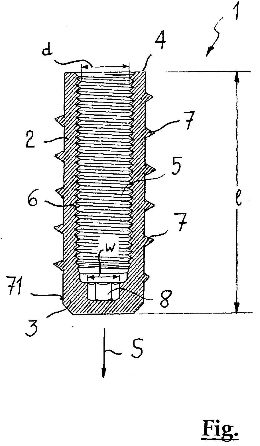
- the trained as a self-tapping anchor fastener carries overall the reference numeral 1.
- the dowel 1 has a substantially cylindrical body. 2 on, on whose peripheral surface a helical circumferential cutting edge 7 is formed.
- the self-tapping anchor 1 is shown in the use position, with its front section 3 points in the direction S.
- the cutting edge 7 has at the front portion. 3 an outlet 71 and extends against the setting direction S in the direction of rearward end 1 of the body 2.
- the cutting edge 7 extends with advantage over a substantial part of the longitudinal extent of the body 2 of the dowel.
- the Formation of the cutting edge 7 is known per se from the prior art.
- the biggest radial projection of the helically extending cutting edge 7 is for example about 1.5 mm to about 4 mm.
- the radial projection of the cutting edge 7 increases at the outlet 71 essentially zero. This facilitates the rotating setting of the self-tapping Dowels 1 digging the cutting edge 7 in the wall of a hard ground, For example, concrete, stone, masonry or the like, created receiving bore.
- the illustrated self-tapping anchor 1 has a blind hole 5, which with an internal thread 6 is equipped as load application means.
- the internal thread is running at the mouth of the blind hole 5 at the rear end 4 of the body 2.
- an engaging means 8 is arranged for a setting tool.
- the engaging means 8 has a polygonal, in particular a hexagonal, cross-sectional contour.
- the load application means can also other polygonal cross-sectional contours, for example have three, four, pentagonal, etc. cross-sectional contours. in principle are also all known from the ffertechnik open cross-sectional contours suitable. Examples are simple or crossed slots, Torx contours, star-shaped Contours and the like.
- Availability of setting tools usually also the largest possible total area sought for torque transmission, in a given diameter is writable.
- the engaging means 8 substantially at the same axial height arranged like the outlet of the cutting edge 7. This has the great advantage that the Torque introduction essentially in the immediate vicinity of the outlet 71 of the cutting edge 7 takes place. As a result, the dowel 1 is already before the beginning of the setting process stabilized and tilting and procurzesieren about its axis is prevented. By the optimum torque introduction digs the cutting edge 7 at the beginning of the rotating Setting process quickly in the wall of the mounting hole and stabilized the dowel 1 in addition.
- the diameter d of the blind hole 5 is greater than the diameter or the Width w of the attacking means 8. This makes the setting tool very easy to the bottom the blind hole 5 insertable to engage it with the engaging means 8 for To bring torque transmission.
- the substantially cylindrically shaped Body 2 of the self-tapping anchor 1 is tapered at its front portion 3 formed or fasts. This facilitates the attachment of the anchor 1 to the prepared Bore.
- the fastening element according to the invention usually consists of steel.
- a corrosion resistant steel for special Applications can also be used a corrosion resistant steel.
- the preparation of the anchor is done for example in a cutting Process or preferably in a cost-effective cold forming process.
- the invention is based on the example of a self-tapping anchor with an internally threaded bore been explained. It is understood that the inventive arrangement the offensive also in so-called concrete screws with usually as a hexagon trained head can be provided.
- the described load application may be as a coarse thread, a withworth thread, a metric thread or the like be educated. Threads as load application offer the advantage that a fastener fixed component very easy by loosening the screwed Fixing screw is removable again.
- the load application means also a quick-connection system on a clamping form-fitting basis, a bayonet connection or the like.
- the plea for a Setting tool for torque transmission during setting process essentially is arranged at the same height with the outlet of the cutting edge, the tendency to tilt the fastener reliably counteracted. Unlike the fasteners In the prior art, this makes the torque more immediate Neighborhood of the engagement of the cutting edge in the wall of a prepared Receiving bore initiated. During the setting process, the fastener therefore a very stable position, a Complex Receivesion about its axis due to tilting from the axial Alignment is largely avoided. This also happens with fasteners with only one circumferential cutting edge to no widening of the receiving bore in the mouth area.
- the fastener By introducing the torque in the immediate Neighborhood to the cutting outlet at the front end portion of the body of the fastener optimally engages the cutting edge in the wall of the receiving bore and thus stabilizes the fastener immediately after the beginning the setting process in addition. On multiple cutting, especially three cutting edges to obtain a three-point support before the beginning of the setting process can be omitted become. As a result, the fastener is relatively simple and inexpensive produced.
Landscapes
- Engineering & Computer Science (AREA)
- General Engineering & Computer Science (AREA)
- Mechanical Engineering (AREA)
- Dowels (AREA)
- Processing Of Stones Or Stones Resemblance Materials (AREA)
- Devices For Post-Treatments, Processing, Supply, Discharge, And Other Processes (AREA)
- Connection Of Plates (AREA)
Abstract
Es ist ein Befestigungselement (1) für harte Untergründe, insbesondere für Beton oder
dergleichen, vorgeschlagen, welches einen im wesentlichen zylindrischen Körper (2)
aufweist, an dessen Umfangsfläche wenigstens eine wendelförmig umlaufende
Schneide (7) vorgesehen ist. Die Schneide (7) erstreckt sich von einem setzrichtungsseitigen
(S) vorderen Endabschnitt (3) des Körpers (2) in Richtung dessen rückwärtigen
Endes (4). Ein Angriffsmittel (8) für ein Setzwerkzeug dient beim Setzvorgang zur
Übertragung von Drehmoment. Das Angriffsmittel (8) ist im wesentlichen auf der gleichen
axialen Höhe des Körpers (2) angeordnet wie ein Auslauf (71) der Schneide (7)
am vorderen Endabschnitt (3) des Körpers (2).
Description
Die Erfindung betrifft ein Befestigungselement für harte Untergründe, insbesondere
für Beton, Stein, Mauerwerk oder dergleichen, gemäss dem Oberbegriff des Patentanspruchs
1.The invention relates to a fastener for hard surfaces, in particular
for concrete, stone, masonry or the like, according to the preamble of the
Zur Befestigung von Bauteilen an harten Untergründen, wie beispielsweise Beton, Stein, Ziegelmauerwerk und dergleichen, werden meist Dübel als Befestigungselemente verwendet. Diese besitzen üblicherweise einen hülsenförmigen Dübelkörper aus Metall oder Stahl, der in einer im Untergrund vorbereiteten Bohrung verankert wird, und Lastangriffsmittel, die zur Festlegung des Bauteils mit dem eigentlichen Befestigungsmittel, beispielsweise einer Schraube, einem Bolzen oder dergleichen, zusammenwirken. Die Lastangriffsmittel sind meist Innengewinde, die in der Innenwandung des mit einer Bohrung versehenen, hülsenförmigen Dübelkörpers vorgesehen sind. Es können aber auch andere Arten von Lastangriffsmitteln, beispielsweise Bajonettanschlüsse oder weitere dergleichen formschlüssige Verbindungen, vorgesehen sein. Eine weitere Art von gebräuchlichen Lastangriffsmitteln sind beispielsweise auch steckbare Schnellverschlüsse mit federnd in die Strukturierung einer Gewindestange eingreifenden Verriegelungselementen und dergleichen. Die Verankerung der Dübel im Untergrund erfolgt meist durch ein radiales Aufweiten eines Spreizbereichs am in Setzrichtung vorderen Endabschnitt des Dübelkörpers. Dazu wird ein üblicherweise konisches Spreizelement unter radialem Aufspreizen des Spreizbereichs in einer Bohrung des hülsenförmigen Dübelkörpers verschoben. Der Spreizkonus ist dabei meist bereits innerhalb der Bohrung angeordnet und wird schlagend in der Bohrung vorgetrieben. Bei sogenannten Aussenkonusdübeln ist der Spreizkörper am vorderen Ende des Dübelkörpers festgeklemmt. Zum Verankern derartiger Befestigungselemente im Untergrund wird der meist metallische, hülsenförmige Dübelkörper über den sich am Bohrlochgrund abstützenden Spreizkörper aus Metall getrieben. Dabei wird der Spreizbereich radial aufgeweitet. For fastening components to hard surfaces, such as concrete, Stone, brickwork and the like, are usually dowels as fasteners used. These usually have a sleeve-shaped dowel body Metal or steel anchored in a hole prepared underground and load application means for fixing the component with the actual fastener, For example, a screw, a bolt or the like, cooperate. The load application means are usually internal threads, which are in the inner wall provided with a bore, sleeve-shaped dowel body are provided. It but also other types of load application, such as bayonet connectors or other such positive connections, be provided. A Another type of common load application means, for example, pluggable Quick-release fasteners with resiliently engaging in the structuring of a threaded rod Locking elements and the like. The anchoring of the dowels in the underground is usually done by a radial expansion of a spread on the setting direction front end portion of the dowel body. This is usually a conical Spreizelement under radial spreading of the expansion in a bore of the moved sleeve-shaped dowel body. The expansion cone is usually already within arranged the bore and is propelled in the bore beating. at so-called outer cone dowels is the expansion body at the front end of the dowel body clamped. For anchoring such fasteners in the underground is the most metallic, sleeve-shaped dowel body on the bottom of the hole supporting spreader made of metal. This is the spread area radially expanded.
Die Relativverschiebung zwischen dem hülsenförmigen Dübelkörper und dem konischen Spreizkörper erfolgt durch axiale Schläge, mit denen der Spreizkonus in der Bohrung vorgetrieben bzw. der Dübelkörper auf den Spreizkörper aufgetrieben wird. Durch den schlagenden Setzvorgang sind die beschriebenen Befestigungselemente nicht für jeden Untergrund geeignet. In Ziegelmauerwerk, beispielsweise, kommt es durch die Wucht der axialen Schläge oft zu Beschädigungen des Ziegels. Danach ist keine sichere Verankerung mehr möglich. Aber auch in porösem Sandstein oder dergleichen Untergründen kann es durch die axialen Schläge auf den Spreizkörper bzw. auf den hülsenförmigen Dübelkörper zu Beschädigungen kommen, die dazu führen, dass die geforderten Lastwerte nicht erreicht werden. Die kraftschlüssige Verankerung dieser Dübelgattung im Untergrund durch radiales Aufspreizen des Spreizbereichs des Dübelkörpers ist in vielen Anwendungsfällen nachteilig. Infolge der relativ hohen Spreizkräfte müssen vorgegebene Mindestrand- und Mindestachsabstände eingehalten werden, um die Sicherheit des Befestigungspunktes gewährleisten zu können. Dies schränkt die Möglichkeiten zur Befestigung von Bauteilen oft in unerwünschter Weise ein.The relative displacement between the sleeve-shaped dowel body and the conical Spreizkörper carried by axial blows, with which the expansion cone in the Drilled hole or the dowel body is distended onto the spreader. The beating setting process are the described fasteners not suitable for every surface. In brickwork, for example, it comes Due to the force of the axial blows often damage the brick. After that is no secure anchorage possible anymore. But also in porous sandstone or the like Substrates may be due to the axial impacts on the spreader or on the sleeve-shaped dowel body to damage, which lead to that the required load values are not reached. The frictional anchorage this Dübelgattung in the underground by radial spreading of the expansion of the Dowel body is disadvantageous in many applications. As a result of the relatively high Spreader forces must comply with specified minimum edge and minimum axial distances to ensure the safety of the point of attachment. This often limits the ability to attach components undesirably one.
Für die Erstellung von Befestigungen mit geringeren Achs- und Randabständen ist bei einer zweiten Gattung von Befestigungselementen eine weitgehend spreizdruckfreie, formschlüssige Verankerung vorgesehen. Bei sogenannten Hinterschnittdübeln besteht die formschlüssige Verankerung darin, dass am Dübelkörper vorgesehene Spreizlappen in eine, meist in der Nähe des Bohrlochgrunds angebrachte Hinterschneidung ausgestellt werden. Die Hinterschneidung im Untergrund muss zuvor gesondert, mit Hilfe von speziellen Hinterschnittgeräten im Bohrloch erstellt werden. Diese Art der Befestigungstechnik ist sehr zeit- und kostenaufwendig. Sie wird daher üblicherweise nur bei besonders sicherheitsrelevanten Befestigungen und insbesondere für Schwerstlastbefestigungen angewandt.For the creation of fasteners with lower axis and edge distances is included a second type of fasteners a largely spreizdruckfreie, positive anchoring provided. In so-called undercut anchors exists the positive anchoring in that provided on the dowel body Spreizlappen in a, mostly near the bottom of the hole mounted undercut to be issued. The undercut in the subsurface must be separated before, with Help be created by special undercut devices in the borehole. This kind of Fastening technology is very time consuming and expensive. It therefore becomes common only for particularly safety-relevant fastenings and in particular for heavy load fastenings applied.
Aus dem Stand der Technik sind auch formschlüssig verankernde Befestigungselemente bekannt, die ohne die gesonderte Erstellung einer Hinterschneidung in einer Bohrung im Untergrund verankert werden. Derartige Befestigungselemente sind beispielsweise in der EP-A-1 174 626 beschrieben. Sie weisen einen im wesentlichen zylindrischen Dübelkörper auf, der mit einer axialen Bohrung versehen ist. Ein Innengewinde in der Bohrungswandung dient als Lastangriffsmittel. Bei einer ersten Ausführungsvariante der beschriebenen Befestigungselemente ist an der Aussenseite des Dübelkörpers eine wendelförmig umlaufende Schneide vorgesehen. Am setzrichtungsseitig abgewandten Ende weist der Dübelkörper ein innenliegendes Angriffsmittel für Setzwerkzeuge auf. Ein zweites beschriebenes Befestigungselement weist einen zweiteiligen Dübelkörper mit unterscheidlichen Durchmessern auf. An einen zylindrischen Schaft schliesst entgegen der Setzrichtung ein im wesentlichen zylindrischer Anschlussteil an. Die Aussenseite des zylindrischen Schafts ist mit wenigstens einer wendelförmig umlaufenden Schneide versehen. Der zylindrische Anschlussteil weist eine Sacklochbohrung auf, die mit einem Innengewinde versehen ist. Am Grund der Sacklochbohrung des Anschlussteils ist ein Angriffsmittel für Setzwerkzeuge vorgesehen. Die beschriebenen Befestigungselemente werden drehend in eine vorbereitete Aufnahmebohrung eingeschraubt. Dabei gräbt sich die am Dübelkörper oder am zylindrischen Schaft vorgesehene Schneide in die Bohrlochwandung und erzeugt eine im wesentlichen formschlüssige Verankerung. Die eigentliche Festlegung eines Bauteils erfolgt über eine Schraube oder dergleichen, die in die Sacklochbohrung des Dübelkörpers bzw. des Anschlussteils eingeschraubt wird.From the prior art are also form-fitting anchoring fasteners known, without the separate creation of an undercut in a bore anchored in the underground. Such fasteners are, for example in EP-A-1 174 626. They have a substantially cylindrical Dowel body, which is provided with an axial bore. An internal thread in the bore wall serves as load application means. In a first embodiment the fasteners described is on the outside of the dowel body provided a helically rotating cutting edge. At the direction of the direction facing away from the dowel body an internal attack means for Setting tools on. A second described fastener has a two-piece dowel body with different diameters. To a cylindrical Shaft closes against the setting direction a substantially cylindrical connection part at. The outside of the cylindrical shaft is helical with at least one provided circumferential edge. The cylindrical connection part has a Blind hole on which is provided with an internal thread. At the bottom of the blind hole the connecting part is provided a means of attack for setting tools. The described fasteners are rotating in a prepared receiving bore screwed. This digs on the dowel body or on the cylindrical Shank provided cutting edge in the borehole wall and produces a substantially positive anchoring. The actual definition of a component takes place via a screw or the like, in the blind hole of the dowel body or the connection part is screwed.
Weiters sind aus dem Stand der Technik auch sogenannte Betonschrauben bekannt. Diese weisen einen zylindrischen Schaft auf, dessen Aussenseite mit wenigstens einer wendelförmigen Schneide versehen ist. Am setzrichtungsseitig abgewandten Ende weist der Schaft einen üblicherweise als Sechskant ausgebildeten Kopf auf. Der Kopf dient als Angriffsmittel zur Drehmomentübertragung beim Einschrauben der Betonschraube in einer vorbereitete Aufnahmebohrung und gleichzeitig zur Festlegung eines Bauteils. Beim Einschrauben gräbt sich die Schneide in die Wandung der Aufnahmebohrung und erzeugt so eine im wesentlichen formschlüssige Verankerung.Furthermore, so-called concrete screws are known from the prior art. These have a cylindrical shaft, the outside with at least one helical cutting edge is provided. At the direction of the direction facing away from the end The shaft has a head, which is usually designed as a hexagon. The head serves as a means of attack for torque transmission when screwing in the concrete screw in a prepared receiving hole and at the same time establishing a Component. When screwing the blade digs into the wall of the mounting hole and thus produces an essentially positive anchoring.
Nachteilig an diesen aus dem Stand der Technik bekannten, selbstschneidenden Befestigungselementen bzw. Betonschrauben ist, dass sie beim Setzvorgang eine grosse Tendenz zu kippen aufweisen und beim Setzvorgang wie ein Kreisel mehr oder weniger regelmässig um ihre Achse präzesieren. Dadurch ist der Setzvorgang deutlich erschwert. Durch das Kippen des Befestigungselements bzw. der Betonschraube wird beim Setzvorgang die Aufnahmebohrung an ihrer Mündung und über eine nicht unbeträchtliche Länge ihrer axialen Erstreckung radial aufgeweitet. Dies kann dazu führen, dass das Befestigungselement in seinem setzrichtungsseitig rückwärtigen Abschnitt nicht mehr in der Wandung der Aufnahmebohrung verankert ist und die geforderten Haltewerte nicht mehr erreicht werden.A disadvantage of these known from the prior art, self-tapping fasteners or concrete screws is that they are in the setting process a large Have tendency to tilt and during setting process like a gyroscope more or less regularly precess around its axis. As a result, the setting process is much more difficult. By tilting the fastener or the concrete screw is during the setting process, the receiving bore at its mouth and a not inconsiderable Length of its axial extent radially expanded. This can cause that the fastening element in its setting direction side rear portion no longer anchored in the wall of the receiving bore and the required Holding values can no longer be achieved.
Um der Kipptendenz beim Setzvorgang entgegenzuwirken, sind bei einem weiteren aus dem Stand der Technik bekannten Befestigungselement an der Aussenseite des Dübelkörpers drei wendelförmig umlaufende Schneiden vorgesehen, die an der Dübelspitze an einem Umfangskreis auslaufen. Dadurch weist das Befestigungselement beim Ansetzen an die Aufnahmebohrung eine Dreipunkt-Auflage auf. Beim Setzvorgang graben sich die drei Schneiden gleichzeitig und gleichmässig in die Wandung der Aufnahmebohrung ein. Ein Kippen des Befestigungselements kann dadurch weitgehend vermieden werden. Die Herstellung des Befestigungselements mit drei wendelförmig umlaufenden Schneiden ist jedoch relativ aufwändig und verteuert das Produkt.To counteract the tendency to tilt during the setting process, are in another known from the prior art fastener on the outside of the Dowel body three helical circumferential cutting provided at the dowel tip to expire on a circumferential circle. As a result, the fastening element when attaching to the mounting hole on a three-point support. During the setting process dig the three edges simultaneously and evenly into the wall of the Receiving hole. Tilting of the fastener can thereby largely be avoided. The manufacture of the fastener with three helical Circumferential cutting is relatively complex and expensive the product.
Es ist daher Aufgabe der vorliegenden Erfindung, diesen Nachteilen der Befestigungselemente des Stands der Technik abzuhelfen. Es soll ein Befestigungselement geschaffen werden, welches Befestigungen mit kleinen Achs- und Randabständen ermöglicht. Die Tendenz des Befestigungselements, beim Setzvorgang zu kippen und um seine Achse zu präzesieren, soll weitgehend beseitigt sein. Dabei soll das Befestigungselement einfach und kostengünstig herstellbar sein.It is therefore an object of the present invention, these disadvantages of the fasteners of the prior art. It is intended to create a fastener which allows fixings with small axis and edge distances. The tendency of the fastener to tilt during setting and its Axis to precess, should be largely eliminated. In this case, the fastener be easy and inexpensive to produce.
Die Lösung dieser Aufgaben besteht in einem Befestigungselement, welches die im
kennzeichnenden Abschnitt des Patentanspruchs 1 angeführten Merkmale aufweist.
Weiterbildungen und/oder vorteilhafte Ausführungsvarianten der Erfindung sind
Gegenstand der abhängigen Patentansprüche.The solution to these problems consists in a fastener, which in the
having characteristic features of the
Die Erfindung schlägt ein Befestigungselement für harte Untergründe, insbesondere für Beton oder dergleichen, vor, welches einen im wesentlichen zylindrischen Körper aufweist, an dessen Umfangsfläche wenigstens eine wendelförmig umlaufende Schneide vorgesehen ist. Die Schneide erstreckt sich von einem setzrichtungsseitigen vorderen Endabschnitt des Körpers in Richtung seines rückwärtigen Endes. Ein Angriffsmittel für ein Setzwerkzeug dient beim Setzvorgang zur Übertragung von Drehmoment. Das Angriffsmittel ist im wesentlichen auf der gleichen axialen Höhe des Körpers angeordnet wie ein Auslauf der Schneide am vorderen Endabschnitt des Körpers.The invention proposes a fastening element for hard substrates, in particular for concrete or the like, which has a substantially cylindrical body has, at its peripheral surface at least one helically encircling Cutting edge is provided. The cutting edge extends from a setting direction side front end portion of the body toward its rear end. A plea for a setting tool is used in the setting process for the transmission of torque. The engagement means is at substantially the same axial height of the Body arranged as an outlet of the cutting edge at the front end portion of the body.
Indem des Angriffsmittel für ein Setzwerkzeug zur Drehmomentübertragung beim Setzvorgang im wesentlichen auf gleicher Höhe mit dem Auslauf der Schneide angeordnet ist, wird der Kipptendenz des Befestigungselements zuverlässig entgegengewirkt. Im Gegensatz zu den Befestigungselementen des Stands der Technik wird dadurch das Drehmoment in unmittelbarer Nachbarschaft des Eingriffs der Schneide in die Wandung einer vorbereiteten Aufnahmebohrung eingeleitet. Beim Setzvorgang weist das Befestigungselement daher eine sehr stabile Lage auf; eine Präzesion um seine Achse infolge Kippens aus der axialen Ausrichtung wird weitgehend vermieden. Dadurch kann auch bei einem Befestigungselement mit nur einer umlaufenden Schneide ein Aufweiten der Aufnahmebohrung im Mündungsbereich verhindert werden. Durch das Einleiten des Drehmoments in unmittelbarer Nachbarschaft zum Schneidenauslauf am vorderen Endabschnitt des Körpers des Befestigungselements greift die Schneide optimal in die Wandung der Aufnahmebohrung ein und stabilisiert so das Befestigungselement unmittelbar nach Beginn des Setzvorgangs zusätzlich. Auf Mehrfachschneiden, beispielsweise drei Schneiden zur Erzielung einer Dreipunktauflage, vor Beginn des Setzvorgangs kann verzichtet werden. Dadurch ist das Befestigungselement relativ einfach und kostengünstig herstellbar. Beispielsweise kann das Befestigungselement mit der einzelnen wendelförmig umlaufenden Schneide in einem Kaltumformprozess aus Stahl hergestellt werden. Für besondere Einsatzbedingungen kann das Befestigungselement auch aus einer rostfreien Stahllegierung oder dergleichen hergestellt sein.By the engagement means for a setting tool for torque transmission during Setting process arranged substantially at the same height with the outlet of the cutting edge is, the tilting tendency of the fastener is reliably counteracted. In contrast to the fasteners of the prior art is characterized the torque in the immediate vicinity of the engagement of the cutting edge in initiated the wall of a prepared receiving bore. During the setting process Therefore, the fastener has a very stable position; a precession about his Axis due to tilting from the axial alignment is largely avoided. As a result, even with a fastener with only one circumferential Cutting an expansion of the receiving bore in the mouth area can be prevented. By introducing the torque in the immediate vicinity of Cutting spout at the front end portion of the body of the fastener engages the cutting edge optimally in the wall of the receiving bore and stabilizes so the fastener immediately after the beginning of the setting process in addition. On Multiple cutting, for example three cutting edges to achieve a three-point support, before the beginning of the setting process can be dispensed with. This is the fastener relatively easy and inexpensive to produce. For example, that can Fastener with the single helically rotating cutting edge in one Cold forming process can be made of steel. For special conditions of use The fastener may also be made of a stainless steel alloy or the like be prepared.
Das Angriffsmittel zur Drehmomentübertragung weist zweckmässigerweise eine polygone Querschnittskontur auf. Vorzugsweise ist die Querschnittskontur regelmässig mehreckig, insbesondere drei-, vier-, fünf- oder sechseckig ausgebildet. Setzwerkzeuge mit derartigen Querschnittskonturen sind hinlänglich bekannt und in unterschiedlichen Durchmessern erhältlich. Das Lastangriffmittel kann jedoch auch andere Querschnittkonturen aufweisen. Prinzipiell sind alle aus der Schraubtechnik bekannten offenen Querschnittskonturen geeignet. Beispiele dafür sind einfache oder gekreuzte Schlitze, Torx-Konturen, sternförmige Konturen und dergleichen. Bei der Auswahl der Querschnittskontur wird neben der Verfügbarkeit von Setzwerkzeugen in der Regel auch eine möglichst grosse Gesamtfläche zur Drehmomentübertragung angestrebt, die in einen vorgegebenen Durchmesser einschreibbar ist.The attack means for torque transmission has expediently a polygonal Cross-sectional contour on. Preferably, the cross-sectional contour is regular polygonal, in particular three-, four-, five- or hexagonal formed. Installation equipment With such cross-sectional contours are well known and in different Diameters available. However, the load application means can also have other cross-sectional contours exhibit. In principle, all known from the screwing open Cross-sectional contours suitable. Examples are simple or crossed Slits, Torx contours, star-shaped contours and the like. When choosing the Cross-sectional contour is in addition to the availability of setting tools in the rule also sought the largest possible total area for torque transmission, the can be written in a predetermined diameter.
Das Angriffsmittel ist mit Vorteil innerhalb des Körpers des Befestigungselements angeordnet und durch eine am rückwärtigen Ende des Körpers mündende Bohrung erreichbar. Diese Ausführungsvariante ist bei einer klassischen zylindrischen Betonschraube mit Sechskantkopf ebenso umsetzbar wie bei einer selbstschneidenden dübelartigen Ausführungsvariante des Befestigungselements.The engaging means is advantageously disposed within the body of the fastener and reachable by a hole opening at the rear end of the body. This variant is in a classic cylindrical concrete screw with hexagon head as feasible as a self-tapping dowel-like Embodiment of the fastener.
Bei einer Ausführungsvariante des Befestigungselements als selbstschneidender Einschraubdübel weist die Bohrung im Körper des Befestigungselements einen Durchmesser auf, der grösser ist als ein Durchmesser des Angriffsmittels. Dadurch kann das Setzwerkzeug ungehindert durch die Mündung der Bohrung am rückwärtigen Ende des Körpers eingeführt und mit dem Angriffsmittel in Eingriff gebracht werden. Das Setzwerkzeug kann dabei beispielsweise sehr einfach nach der Art von bekannten Schraubwerkzeugen ausgebildet sein.In one embodiment of the fastener as a self-tapping screw-in the bore in the body of the fastener has a diameter which is greater than a diameter of the plea. This can do that Setting tool unhindered through the mouth of the hole at the rear end of the body are introduced and brought into engagement with the attack. The Setting tool can, for example, very easy in the manner of known Be designed screwing.
Die Bohrung im Körper ist mit einem Lastangriffsmittel ausgestattet, welche vorzugsweise entgegen der Setzrichtung nach rückwärts an das Angriffsmittel anschliesst. Das Lastangriffmittel kann ein Schnellanbindesystem auf klemmender Formschlussbasis, ein Bajonettanschluss oder dergleichen sein. In einer bevorzugten Ausführungsvariante des Befestigungselements ist das Lastangriffsmittel ein Innengewinde. Das Innengewinde kann dabei als ein Steilgewinde, ein Withworth-Gewinde, ein metrisches Gewinde oder dergleichen ausgebildet sein. Gewinde als Lastangriffsmittel bieten den Vorteil, dass ein am Befestigungsmittel festgelegtes Bauteil sehr einfach durch Lösen der eingeschraubten Befestigungsschraube wieder demontierbar ist.The bore in the body is equipped with a load application means, which preferably against the setting direction backwards to the attacking means connects. The Load application means can be a quick-connect system on a clamping form-fitting basis, a bayonet connection or the like. In a preferred embodiment of the fastening element, the load application means is an internal thread. The internal thread Can be used as a coarse thread, a Withworth thread, a metric thread or the like may be formed. Threads as load application offer the Advantage that a fixed to the fastener component very easy by loosening the screwed fastening screw is removable again.
Indem der vordere Endabschnitt des Körpers des Befestigungselements zum vorderen Ende hin verjüngt ausgebildet ist, wird das Ansetzen und Einschrauben des Befestigungselements in die vorbereitete Aufnahmebohrung im Untergrund erleichtert. Die verjüngte Ausbildung des voderen Endabschnitts umfasst dabei auch Anfasungen oder eine kalottenförmige oder ähnliche Ausbildung des Vorderendes des Körpers.By the front end portion of the body of the fastener to the front Tapered end is formed, the attachment and screwing of the fastener facilitated in the prepared receiving hole in the ground. The Rejuvenated training of the voderen end section includes thereby chamfers or a dome-shaped or similar formation of the front end of the body.
Die wendelförmig umlaufende Schneide erstreckt sich mit Vorteil über einen wesentlichen Teil der Längserstreckung des Körpers des Befestigungselements. Die Schneide gräbt sich beim drehenden Setzvorgang in die Wandung der vorbereiteten Aufnahmebohrung und erstellt eine formschlüssige Verankerung. Die Länge der formschlüssigen Verankerung in der Aufnahmebohrung ist ein Mass für die erzielbaren Lastwerte.The helically circumferential cutting edge advantageously extends over a substantial amount Part of the longitudinal extension of the body of the fastener. The cutting edge digs in the rotating setting process in the wall of the prepared receiving bore and creates a positive anchoring. The length of the positive Anchoring in the receiving bore is a measure of the achievable load values.
Wie bereits im Vorstehenden ausgeführt wurde, ist die erfindungsgemässe Ausbildung für selbstscheidende dübelförmige Ausführungsvarianten ebenso geeignet wie für die aus dem Stand der Technik hinlänglich bekannten sogenannten Betonschrauben, welche über ihren meist sechskantigen Kopf ein Bauteil festlegen. In einer Variante für Betonschrauben ist der Körper mit einer axialen Bohrung versehen, die am Kopf mündet. Das Angriffsmittel ist über diese Bohrung erreichbar. Die Bohrung weist dabei zweckmässigerweise im wesentlichen über ihre gesamte sich vom rückwärtigen Ende des Körpers zum Angriffsmittel erstreckende Länge einen Querschnitt auf, der demjenigen des Angriffsmittels entspricht. Das etwa auf der gleichen Höhe wie der Auslauf der Schneide angeordnete Angriffsmittel setzt sich in dieser Ausführungsvariante zum rückwärtigen Ende der Betonschraube fort. Die daraus resultierende Gesamtfläche zur Drehmomentübertragung ist bei dieser Ausführungsvariante relativ gross.As already stated above, the embodiment according to the invention is suitable for selbstscheidende dowel-shaped embodiments as well as for the From the prior art well-known so-called concrete screws, which Define a component via its mostly hexagonal head. In a variant for Concrete screws, the body is provided with an axial bore, which opens at the head. The attacking agent is accessible via this hole. The hole points conveniently substantially over its entire length from the rear end The length of the body to the attack means extending a cross-section, the one of the plea. The approximately at the same height as the spout the incision arranged attack means is in this embodiment to backward end of the concrete screw. The resulting total area for Torque transmission is relatively large in this embodiment.
Das Angriffsmittel ist über eine am rückwärtigen Ende des Körpers des Befestigungsmittels mündende axiale Bohrung erreichbar. Dabei kann die Bohrung als Durchgangsbohrung ausgebildet sein. Vorzugsweise ist die axiale Bohrung im Körper jedoch als eine Sacklochbohrung ausgebildet und ist das Angriffsmittel am Grund der Sacklochbohrung angeordnet. Bei dieser Ausführungsvariante ist die Positions des Eingriffs des Setzwerkzeugs mit dem Angriffsmittel eindeutig festgelegt, und es ist eine optimale Drehmomentübertragung in unmittelbarer Nachbarschaft zum Auslauf der Schneide gewährleistet.The engaging means is via a at the rear end of the body of the fastener reachable axial bore. The hole can as a through hole be educated. Preferably, however, the axial bore in the body formed as a blind hole and the engaging means at the bottom of the blind hole arranged. In this embodiment, the position of the engagement of the setting tool with the engaging means uniquely determined, and it is optimal Torque transmission in the immediate vicinity of the outlet of the cutting edge guaranteed.
Weitere Vorteile und Merkmale ergeben sich aus der nachfolgenden Beschreibung einer beispielsweisen Ausführungsvariante der Erfindung unter Bezugnahme auf die einzige schematische Zeichnung, welche einen Axialschnitt eines als selbstschneidender Dübel ausgebildeten Befestigungselements zeigt.Further advantages and features will become apparent from the following description of a Exemplary embodiment of the invention with reference to the single schematic drawing showing an axial section of a self-tapping Dowel formed fastener shows.
Das als selbstschneidender Dübel ausgebildete Befestigungselement trägt gesamthaft
das Bezugszeichen 1. Der Dübel 1 weist einen im wesentlichen zylindrischen Körper 2
auf, an dessen Umfangsfläche eine wendelartig umlaufende Schneide 7 ausgebildet ist.
Der selbstschneidende Dübel 1 ist in Gebrauchsstellung dargestellt, wobei sein Vorderabschnitt
3 in die Setzrichtung S weist. Die Schneide 7 weist am Vorderabschnitt 3
einen Auslauf 71 auf und erstreckt sich entgegen der Setzrichtung S in Richtung des
rückwärtigen Endes 1 des Körpers 2. Die Schneide 7 erstreckt sich dabei mit Vorteil
über einen wesentlichen Teil der Längserstreckung des Körpers 2 des Dübels. Die
Ausbildung der Schneide 7 ist an sich aus dem Stand der Technik bekannt. Der grösste
radiale Überstand der wendelartig verlaufenden Schneide 7 beträgt beispielsweise etwa
1,5 mm bis etwa 4 mm. Der radiale Überstand der Schneide 7 nimmt am Auslauf 71
im wesentlichen auf Null ab. Dies erleichtert beim drehenden Setzen des selbstschneidenden
Dübels 1 das Eingraben der Schneide 7 in die Wandung einer im harten Untergrund,
beispielsweise Beton, Stein, Mauerwerk oder dergleichen, erstellten Aufnahmebohrung.The trained as a self-tapping anchor fastener carries overall
the
Der dargestellte selbstschneidende Dübel 1 weist eine Sacklochbohrung 5 auf, die mit
einem Innengewinde 6 als Lastangriffsmittel ausgestattet ist. Das Innengewinde läuft
an der Mündung der Sacklochbohrung 5 am rückwärtigen Ende 4 des Körpers 2 aus.
Am Grund der Sacklochbohrung 5 ist ein Angriffsmittel 8 für ein Setzwerkzeug angeordnet.
Bei dem dargestellten Ausführungsbeispiel weist das Angriffsmittel 8 eine polygonale,
insbesondere eine sechseckige, Querschnittskontur auf. The illustrated self-tapping
Das Lastangriffmittel kann jedoch auch andere polygonale Querschnittkonturen, beispielsweise drei-, vier-, fünfeckige usw. Querschnittkonturen aufweisen. Prinzipiell sind auch alle aus der Schraubtechnik bekannten offenen Querschnittskonturen geeignet. Beispiele dafür sind einfache oder gekreuzte Schlitze, Torx-Konturen, sternförmige Konturen und dergleichen. Bei der Auswahl der Querschnittskontur wird neben der Verfügbarkeit von Setzwerkzeugen in der Regel auch eine möglichst grosse Gesamtfläche zur Drehmomentübertragung angestrebt, die in einen vorgegebenen Durchmesser einschreibbar ist.However, the load application means can also other polygonal cross-sectional contours, for example have three, four, pentagonal, etc. cross-sectional contours. in principle are also all known from the Schraubtechnik open cross-sectional contours suitable. Examples are simple or crossed slots, Torx contours, star-shaped Contours and the like. When selecting the cross-sectional contour is next to the Availability of setting tools usually also the largest possible total area sought for torque transmission, in a given diameter is writable.
Zum Unterschied von den selbstschneidenden Befestigungsmitteln für harte Untergründe
des Stands der Technik ist bei dem erfindungsgemässen selbstschneidenden
Befestigungsmittel 1 das Angriffsmittel 8 im wesentlichen auf gleicher axialer Höhe
angeordnet wie der Auslauf der Schneide 7. Dies hat den grossen Vorteil, dass die
Drehmomenteinleitung im wesentlichen in unmittelbarer Nachbarschaft zum Auslauf
71 der Schneide 7 erfolgt. Dadurch ist der Dübel 1 bereits vor Beginn des Setzvorgangs
stabilisiert und ein Kippen und Präzesieren um seine Achse wird verhindert. Durch
die optimale Drehmomenteinleitung gräbt sich die Schneide 7 bei Beginn des drehenden
Setzvorgangs schnell in die Wandung der Aufnahmebohrung ein und stabilisiert
den Dübel 1 zusätzlich.In contrast to the self-tapping fasteners for hard surfaces
The prior art is in the inventive self-tapping
Fastening means 1, the engaging
Der Durchmesser d der Sacklochbohrung 5 ist grösser als der Durchmesser bzw. die
Weite w des Angriffsmittels 8. Dadurch ist das Setzgerät sehr einfach bis in den Grund
der Sacklochbohrung 5 einführbar, um es in Eingriff mit dem Angriffsmittel 8 zur
Drehmomentübertragung zu bringen. Der im wesentlichen zylindrisch ausgebildete
Körper 2 des selbstschneidenden Dübels 1 ist an seinem Vorderabschnitt 3 verjüngt
bzw. gefast ausgebildet. Dies erleichtert das Ansetzen des Dübels 1 an die vorbereitete
Aufnahmebohrung.The diameter d of the
Das erfindungsgemässe Befestigungselement besteht üblicherweise aus Stahl. Für besondere Anwendungen kann auch ein korrosionsbeständiger Stahl verwendet werden. The fastening element according to the invention usually consists of steel. For special Applications can also be used a corrosion resistant steel.
Die Herstellung des Dübels erfolgt erfolgt beispielsweise in einem spanabhebenden Verfahren oder vorzugsweise in einem kostengünstigen Kaltumformverfahren.The preparation of the anchor is done for example in a cutting Process or preferably in a cost-effective cold forming process.
Die Erfindung ist am Beispiel eines selbstschneidenden Dübels mit einer Innengewindebohrung erläutert worden. Es versteht sich, dass die erfindungsgemässe Anordnung der Angriffsmittel auch bei sogenannten Betonschrauben mit üblicherweise als Sechskant ausgebildetem Kopf vorgesehen sein kann. Das beschriebene Lastangriffsmittel kann als ein Steilgewinde, ein Withworth-Gewinde, ein metrisches Gewinde oder dergleichen ausgebildet sein. Gewinde als Lastangriffsmittel bieten den Vorteil, dass ein am Befestigungsmittel festgelegtes Bauteil sehr einfach durch Lösen der eingeschraubten Befestigungsschraube wieder demontierbar ist. Neben einem Innengewinde kann das Lastangriffmittel auch ein Schnellanbindesystem auf klemmender Formschlussbasis, ein Bajonettanschluss oder dergleichen sein.The invention is based on the example of a self-tapping anchor with an internally threaded bore been explained. It is understood that the inventive arrangement the offensive also in so-called concrete screws with usually as a hexagon trained head can be provided. The described load application may be as a coarse thread, a withworth thread, a metric thread or the like be educated. Threads as load application offer the advantage that a fastener fixed component very easy by loosening the screwed Fixing screw is removable again. In addition to an internal thread can the load application means also a quick-connection system on a clamping form-fitting basis, a bayonet connection or the like.
Indem bei dem erfindungsgemässen Befestigungselement das Angriffsmittel für ein Setzwerkzeug zur Drehmomentübertragung beim Setzvorgang im wesentlichen auf gleicher Höhe mit dem Auslauf der Schneide angeordnet ist, wird der Kipptendenz des Befestigungselements zuverlässig entgegengewirkt. Im Gegensatz zu den Befestigungselementen des Stands der Technik wird dadurch das Drehmoment in unmittelbarer Nachbarschaft des Eingriffs der Schneide in die Wandung einer vorbereiteten Aufnahmebohrung eingeleitet. Beim Setzvorgang weist das Befestigungselement daher eine sehr stabile Lage auf, eine Präzesion um seine Achse infolge Kippens aus der axialen Ausrichtung wird weitgehend vermieden. Dadurch kommt es auch mit Befestigungselemente mit nur einer umlaufenden Schneide zu keinem Aufweiten der Aufnahmebohrung im Mündungsbereich. Durch das Einleiten des Drehmoments in unmittelbarer Nachbarschaft zum Schneidenauslauf am vorderen Endabschnitt des Körpers des Befestigungselements greift die Schneide optimal in die Wandung der Aufnahmebohrung ein und stabilisiert so das Befestigungselement unmittelbar nach Beginn des Setzvorgangs zusätzlich. Auf Mehrfachschneiden, insbesondere drei Schneiden zur Erzielung einer Dreipunktauflage vor Beginn des Setzvorgangs kann verzichtet werden. Dadurch ist das Befestigungselement relativ einfach und kostengünstig herstellbar.By in the inventive fastener the plea for a Setting tool for torque transmission during setting process essentially is arranged at the same height with the outlet of the cutting edge, the tendency to tilt the fastener reliably counteracted. Unlike the fasteners In the prior art, this makes the torque more immediate Neighborhood of the engagement of the cutting edge in the wall of a prepared Receiving bore initiated. During the setting process, the fastener therefore a very stable position, a Präzesion about its axis due to tilting from the axial Alignment is largely avoided. This also happens with fasteners with only one circumferential cutting edge to no widening of the receiving bore in the mouth area. By introducing the torque in the immediate Neighborhood to the cutting outlet at the front end portion of the body of the fastener optimally engages the cutting edge in the wall of the receiving bore and thus stabilizes the fastener immediately after the beginning the setting process in addition. On multiple cutting, especially three cutting edges to obtain a three-point support before the beginning of the setting process can be omitted become. As a result, the fastener is relatively simple and inexpensive produced.
Claims (10)
Applications Claiming Priority (2)
| Application Number | Priority Date | Filing Date | Title |
|---|---|---|---|
| CH20302003 | 2003-11-28 | ||
| CH20302003 | 2003-11-28 |
Publications (2)
| Publication Number | Publication Date |
|---|---|
| EP1536149A2 true EP1536149A2 (en) | 2005-06-01 |
| EP1536149A3 EP1536149A3 (en) | 2008-07-23 |
Family
ID=34438166
Family Applications (1)
| Application Number | Title | Priority Date | Filing Date |
|---|---|---|---|
| EP04405714A Withdrawn EP1536149A3 (en) | 2003-11-28 | 2004-11-17 | Fastening element |
Country Status (1)
| Country | Link |
|---|---|
| EP (1) | EP1536149A3 (en) |
Cited By (12)
| Publication number | Priority date | Publication date | Assignee | Title |
|---|---|---|---|---|
| EP1760330A1 (en) | 2005-09-02 | 2007-03-07 | HILTI Aktiengesellschaft | Fastening device for hard substrates |
| JP2007071386A (en) * | 2005-09-02 | 2007-03-22 | Hilti Ag | Fixed element |
| EP1892425A2 (en) | 2006-08-23 | 2008-02-27 | HILTI Aktiengesellschaft | Fastening element for hard substrates |
| EP1760331A3 (en) * | 2005-09-02 | 2012-02-01 | HILTI Aktiengesellschaft | Fastening part for hard substrates |
| US9475109B2 (en) | 2013-12-31 | 2016-10-25 | Simpson Strong-Tie Company, Inc. | Method of manufacturing a hollow externally threaded fastener |
| US9945115B2 (en) | 2013-10-08 | 2018-04-17 | Simpson Strong-Tie Company, Inc. | Concrete anchor |
| WO2020083526A1 (en) * | 2018-10-21 | 2020-04-30 | Excalibur Screwbolts Limited | Improvements in or relating to anchor bolts |
| EP3805179A1 (en) | 2019-10-10 | 2021-04-14 | Hilti Aktiengesellschaft | Multicomponent reaction resin system and use thereof |
| EP3805180A1 (en) | 2019-10-10 | 2021-04-14 | Hilti Aktiengesellschaft | Fastening arrangement with a threaded screw and a hardened mass |
| EP3805178A1 (en) | 2019-10-10 | 2021-04-14 | Hilti Aktiengesellschaft | Storage-stable multicomponent reaction resin system and use thereof |
| USRE48981E1 (en) | 2014-01-14 | 2022-03-22 | Simpson Strong-Tie Company Inc. | Thrust nut |
| EP4116275A1 (en) | 2021-07-08 | 2023-01-11 | Hilti Aktiengesellschaft | Fastening arrangement with a threaded screw and a hardened anorganic mass containing aluminium |
Family Cites Families (2)
| Publication number | Priority date | Publication date | Assignee | Title |
|---|---|---|---|---|
| US3190169A (en) * | 1961-12-04 | 1965-06-22 | Rosan Eng Corp | Insert having internal drive grooves |
| DE29709213U1 (en) * | 1997-05-26 | 1998-09-24 | MiTek Industries GmbH, 63128 Dietzenbach | Tensioning or fastening screw, in particular pipe screw |
-
2004
- 2004-11-17 EP EP04405714A patent/EP1536149A3/en not_active Withdrawn
Cited By (17)
| Publication number | Priority date | Publication date | Assignee | Title |
|---|---|---|---|---|
| EP1760330A1 (en) | 2005-09-02 | 2007-03-07 | HILTI Aktiengesellschaft | Fastening device for hard substrates |
| JP2007071386A (en) * | 2005-09-02 | 2007-03-22 | Hilti Ag | Fixed element |
| DE202005021725U1 (en) | 2005-09-02 | 2009-11-19 | Hilti Aktiengesellschaft | Fixing element for hard surfaces |
| CN1924374B (en) * | 2005-09-02 | 2010-05-26 | 希尔蒂股份公司 | Fastening element for hard constructional components |
| EP1760329A3 (en) * | 2005-09-02 | 2012-02-01 | HILTI Aktiengesellschaft | Fastening part for hard substrates |
| EP1760331A3 (en) * | 2005-09-02 | 2012-02-01 | HILTI Aktiengesellschaft | Fastening part for hard substrates |
| EP1892425A2 (en) | 2006-08-23 | 2008-02-27 | HILTI Aktiengesellschaft | Fastening element for hard substrates |
| US9945115B2 (en) | 2013-10-08 | 2018-04-17 | Simpson Strong-Tie Company, Inc. | Concrete anchor |
| US9475109B2 (en) | 2013-12-31 | 2016-10-25 | Simpson Strong-Tie Company, Inc. | Method of manufacturing a hollow externally threaded fastener |
| USRE48981E1 (en) | 2014-01-14 | 2022-03-22 | Simpson Strong-Tie Company Inc. | Thrust nut |
| WO2020083526A1 (en) * | 2018-10-21 | 2020-04-30 | Excalibur Screwbolts Limited | Improvements in or relating to anchor bolts |
| EP3805179A1 (en) | 2019-10-10 | 2021-04-14 | Hilti Aktiengesellschaft | Multicomponent reaction resin system and use thereof |
| EP3805180A1 (en) | 2019-10-10 | 2021-04-14 | Hilti Aktiengesellschaft | Fastening arrangement with a threaded screw and a hardened mass |
| EP3805178A1 (en) | 2019-10-10 | 2021-04-14 | Hilti Aktiengesellschaft | Storage-stable multicomponent reaction resin system and use thereof |
| WO2021069437A1 (en) | 2019-10-10 | 2021-04-15 | Hilti Aktiengesellschaft | Storage-stable multi-component reaction resin system and use thereof |
| EP4116275A1 (en) | 2021-07-08 | 2023-01-11 | Hilti Aktiengesellschaft | Fastening arrangement with a threaded screw and a hardened anorganic mass containing aluminium |
| WO2023280570A1 (en) | 2021-07-08 | 2023-01-12 | Hilti Aktiengesellschaft | Fastening assembly comprising a thread-forming screw and a hardened aluminate-containing inorganic compound |
Also Published As
| Publication number | Publication date |
|---|---|
| EP1536149A3 (en) | 2008-07-23 |
Similar Documents
| Publication | Publication Date | Title |
|---|---|---|
| DE3420375C2 (en) | Dowel | |
| DE3335628C2 (en) | ||
| EP0811775B1 (en) | Self-undercutting anchor | |
| EP0068227A1 (en) | Anchor bolt | |
| DE2607338A1 (en) | KNOCKING DOWEL WITH EXPANSION SLEEVE AND EXPANSION ELEMENT | |
| EP0811774B1 (en) | Self-undercutting anchor | |
| DE2829158A1 (en) | FASTENING ELEMENT WITH ANCHOR BOLT AND SPREAD | |
| EP1536149A2 (en) | Fastening element | |
| DE3110485A1 (en) | SPREADING ANCHOR | |
| EP0774588B1 (en) | Device for mounting a percussion dowel | |
| EP1285172B1 (en) | Self-tapping bush-shaped screwed insert | |
| DE3139174C2 (en) | Anchor bolts | |
| DE3914881A1 (en) | MOUNTING UNIT WITH A SPREADING ANCHOR AND A MOUNTING TOOL | |
| DE3633628C2 (en) | ||
| EP0995913B1 (en) | Anchor for borehole with undercut | |
| DE19756997A1 (en) | Undercut dowels | |
| DE19536786A1 (en) | Fastening element with expansion element | |
| DE19743054A1 (en) | Screw anchor | |
| EP1907714A1 (en) | Thread-cutting concrete anchor | |
| DE3325800A1 (en) | Adhesive anchor | |
| EP0250783B1 (en) | Expanding dowel | |
| DE102004052184A1 (en) | Nail anchor has shaft and a flange which are expandable and have a wall thickness reduction on a peripheral side for expandability and a slot on a peripheral side | |
| EP1036897A1 (en) | Fastening element and method to fasten a facade to a construction | |
| DE3124244C2 (en) | Anchor bolts | |
| DE7129341U (en) | Dowel anchor |
Legal Events
| Date | Code | Title | Description |
|---|---|---|---|
| PUAI | Public reference made under article 153(3) epc to a published international application that has entered the european phase |
Free format text: ORIGINAL CODE: 0009012 |
|
| AK | Designated contracting states |
Kind code of ref document: A2 Designated state(s): AT BE BG CH CY CZ DE DK EE ES FI FR GB GR HU IE IS IT LI LU MC NL PL PT RO SE SI SK TR |
|
| AX | Request for extension of the european patent |
Extension state: AL HR LT LV MK YU |
|
| PUAL | Search report despatched |
Free format text: ORIGINAL CODE: 0009013 |
|
| AK | Designated contracting states |
Kind code of ref document: A3 Designated state(s): AT BE BG CH CY CZ DE DK EE ES FI FR GB GR HU IE IS IT LI LU MC NL PL PT RO SE SI SK TR |
|
| AX | Request for extension of the european patent |
Extension state: AL HR LT LV MK YU |
|
| AKX | Designation fees paid | ||
| REG | Reference to a national code |
Ref country code: DE Ref legal event code: 8566 |
|
| STAA | Information on the status of an ep patent application or granted ep patent |
Free format text: STATUS: THE APPLICATION IS DEEMED TO BE WITHDRAWN |
|
| 18D | Application deemed to be withdrawn |
Effective date: 20090124 |