EP1536146A2 - Strömungsarbeitsmaschine mit Fluidentnahme - Google Patents
Strömungsarbeitsmaschine mit Fluidentnahme Download PDFInfo
- Publication number
- EP1536146A2 EP1536146A2 EP04023822A EP04023822A EP1536146A2 EP 1536146 A2 EP1536146 A2 EP 1536146A2 EP 04023822 A EP04023822 A EP 04023822A EP 04023822 A EP04023822 A EP 04023822A EP 1536146 A2 EP1536146 A2 EP 1536146A2
- Authority
- EP
- European Patent Office
- Prior art keywords
- fluid
- blade
- annular channel
- stator
- rotor
- Prior art date
- Legal status (The legal status is an assumption and is not a legal conclusion. Google has not performed a legal analysis and makes no representation as to the accuracy of the status listed.)
- Granted
Links
Images


Classifications
-
- F—MECHANICAL ENGINEERING; LIGHTING; HEATING; WEAPONS; BLASTING
- F04—POSITIVE - DISPLACEMENT MACHINES FOR LIQUIDS; PUMPS FOR LIQUIDS OR ELASTIC FLUIDS
- F04D—NON-POSITIVE-DISPLACEMENT PUMPS
- F04D29/00—Details, component parts, or accessories
- F04D29/66—Combating cavitation, whirls, noise, vibration or the like; Balancing
- F04D29/68—Combating cavitation, whirls, noise, vibration or the like; Balancing by influencing boundary layers
- F04D29/688—Combating cavitation, whirls, noise, vibration or the like; Balancing by influencing boundary layers especially adapted for liquid pumps
-
- F—MECHANICAL ENGINEERING; LIGHTING; HEATING; WEAPONS; BLASTING
- F01—MACHINES OR ENGINES IN GENERAL; ENGINE PLANTS IN GENERAL; STEAM ENGINES
- F01D—NON-POSITIVE DISPLACEMENT MACHINES OR ENGINES, e.g. STEAM TURBINES
- F01D5/00—Blades; Blade-carrying members; Heating, heat-insulating, cooling or antivibration means on the blades or the members
- F01D5/12—Blades
- F01D5/14—Form or construction
- F01D5/141—Shape, i.e. outer, aerodynamic form
- F01D5/145—Means for influencing boundary layers or secondary circulations
-
- F—MECHANICAL ENGINEERING; LIGHTING; HEATING; WEAPONS; BLASTING
- F02—COMBUSTION ENGINES; HOT-GAS OR COMBUSTION-PRODUCT ENGINE PLANTS
- F02C—GAS-TURBINE PLANTS; AIR INTAKES FOR JET-PROPULSION PLANTS; CONTROLLING FUEL SUPPLY IN AIR-BREATHING JET-PROPULSION PLANTS
- F02C6/00—Plural gas-turbine plants; Combinations of gas-turbine plants with other apparatus; Adaptations of gas-turbine plants for special use
- F02C6/04—Gas-turbine plants providing heated or pressurised working fluid for other apparatus, e.g. without mechanical power output
- F02C6/06—Gas-turbine plants providing heated or pressurised working fluid for other apparatus, e.g. without mechanical power output providing compressed gas
- F02C6/08—Gas-turbine plants providing heated or pressurised working fluid for other apparatus, e.g. without mechanical power output providing compressed gas the gas being bled from the gas-turbine compressor
-
- F—MECHANICAL ENGINEERING; LIGHTING; HEATING; WEAPONS; BLASTING
- F04—POSITIVE - DISPLACEMENT MACHINES FOR LIQUIDS; PUMPS FOR LIQUIDS OR ELASTIC FLUIDS
- F04D—NON-POSITIVE-DISPLACEMENT PUMPS
- F04D29/00—Details, component parts, or accessories
- F04D29/26—Rotors specially for elastic fluids
- F04D29/32—Rotors specially for elastic fluids for axial flow pumps
- F04D29/321—Rotors specially for elastic fluids for axial flow pumps for axial flow compressors
- F04D29/324—Blades
-
- F—MECHANICAL ENGINEERING; LIGHTING; HEATING; WEAPONS; BLASTING
- F04—POSITIVE - DISPLACEMENT MACHINES FOR LIQUIDS; PUMPS FOR LIQUIDS OR ELASTIC FLUIDS
- F04D—NON-POSITIVE-DISPLACEMENT PUMPS
- F04D29/00—Details, component parts, or accessories
- F04D29/40—Casings; Connections of working fluid
- F04D29/52—Casings; Connections of working fluid for axial pumps
- F04D29/522—Casings; Connections of working fluid for axial pumps especially adapted for elastic fluid pumps
- F04D29/526—Details of the casing section radially opposing blade tips
-
- F—MECHANICAL ENGINEERING; LIGHTING; HEATING; WEAPONS; BLASTING
- F04—POSITIVE - DISPLACEMENT MACHINES FOR LIQUIDS; PUMPS FOR LIQUIDS OR ELASTIC FLUIDS
- F04D—NON-POSITIVE-DISPLACEMENT PUMPS
- F04D29/00—Details, component parts, or accessories
- F04D29/40—Casings; Connections of working fluid
- F04D29/52—Casings; Connections of working fluid for axial pumps
- F04D29/54—Fluid-guiding means, e.g. diffusers
- F04D29/541—Specially adapted for elastic fluid pumps
- F04D29/542—Bladed diffusers
-
- F—MECHANICAL ENGINEERING; LIGHTING; HEATING; WEAPONS; BLASTING
- F04—POSITIVE - DISPLACEMENT MACHINES FOR LIQUIDS; PUMPS FOR LIQUIDS OR ELASTIC FLUIDS
- F04D—NON-POSITIVE-DISPLACEMENT PUMPS
- F04D29/00—Details, component parts, or accessories
- F04D29/66—Combating cavitation, whirls, noise, vibration or the like; Balancing
- F04D29/68—Combating cavitation, whirls, noise, vibration or the like; Balancing by influencing boundary layers
- F04D29/681—Combating cavitation, whirls, noise, vibration or the like; Balancing by influencing boundary layers especially adapted for elastic fluid pumps
- F04D29/682—Combating cavitation, whirls, noise, vibration or the like; Balancing by influencing boundary layers especially adapted for elastic fluid pumps by fluid extraction
-
- F—MECHANICAL ENGINEERING; LIGHTING; HEATING; WEAPONS; BLASTING
- F05—INDEXING SCHEMES RELATING TO ENGINES OR PUMPS IN VARIOUS SUBCLASSES OF CLASSES F01-F04
- F05D—INDEXING SCHEME FOR ASPECTS RELATING TO NON-POSITIVE-DISPLACEMENT MACHINES OR ENGINES, GAS-TURBINES OR JET-PROPULSION PLANTS
- F05D2240/00—Components
- F05D2240/20—Rotors
- F05D2240/30—Characteristics of rotor blades, i.e. of any element transforming dynamic fluid energy to or from rotational energy and being attached to a rotor
- F05D2240/307—Characteristics of rotor blades, i.e. of any element transforming dynamic fluid energy to or from rotational energy and being attached to a rotor related to the tip of a rotor blade
-
- Y—GENERAL TAGGING OF NEW TECHNOLOGICAL DEVELOPMENTS; GENERAL TAGGING OF CROSS-SECTIONAL TECHNOLOGIES SPANNING OVER SEVERAL SECTIONS OF THE IPC; TECHNICAL SUBJECTS COVERED BY FORMER USPC CROSS-REFERENCE ART COLLECTIONS [XRACs] AND DIGESTS
- Y02—TECHNOLOGIES OR APPLICATIONS FOR MITIGATION OR ADAPTATION AGAINST CLIMATE CHANGE
- Y02T—CLIMATE CHANGE MITIGATION TECHNOLOGIES RELATED TO TRANSPORTATION
- Y02T50/00—Aeronautics or air transport
- Y02T50/60—Efficient propulsion technologies, e.g. for aircraft
-
- Y—GENERAL TAGGING OF NEW TECHNOLOGICAL DEVELOPMENTS; GENERAL TAGGING OF CROSS-SECTIONAL TECHNOLOGIES SPANNING OVER SEVERAL SECTIONS OF THE IPC; TECHNICAL SUBJECTS COVERED BY FORMER USPC CROSS-REFERENCE ART COLLECTIONS [XRACs] AND DIGESTS
- Y10—TECHNICAL SUBJECTS COVERED BY FORMER USPC
- Y10S—TECHNICAL SUBJECTS COVERED BY FORMER USPC CROSS-REFERENCE ART COLLECTIONS [XRACs] AND DIGESTS
- Y10S415/00—Rotary kinetic fluid motors or pumps
- Y10S415/914—Device to control boundary layer
Definitions
- the present invention relates to fluid flow machines, such as fans, compressors, pumps and fans, both in axial, semi-axial and radial design.
- the working medium or fluid may be gaseous or liquid.
- the invention relates to a fluid flow machine with at least one rotor, wherein the rotor several at comprising rotor blades secured to a rotating shaft. It At least one stator can exist, the stator with fixed stator blades is provided. It can be a case exist, which is the flow through the rotor and stator bounded with a fluid to the outside.
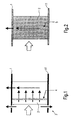
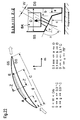
- Figs. 1 and 2 show in a schematic representation of the known in the art solutions. It shows the Fig. 1 is a schematic representation of a housing 1 and a hub 11, between which a fluid, as shown by the large arrow, flows in from the left.
- the reference numeral 2 shows in more schematic Illustration of a shovel whose visible area the "suction side" forms. As by the upward Arrows of Fig. 1, a local air extraction takes place on the blade suction side and in the axial gap in axisymmetric Arrangement. The downward left arrow points an air extraction, the case of a rotor or stator by a Peripheral slot 3 takes place in front of the blade.
- the reference numeral 4 shows a solution in which a stator over a Slot and with a rotor over a perforation, a Slot, holes or a stowage air is taken.
- Fig. 2 shows with the upward arrow a global Air extraction through porous blade surfaces.
- the reference number 5 denotes a stator with a fine-pored, sweatable material.
- the invention is based on the object, a fluid flow machine to create the type mentioned, which while avoiding the prior art, a very effective Boundary layer removal and high efficiency having.
- the turbomachine according to the invention can be one or comprise several stages, each with a rotor and a stator, in some cases, the stage is only by a rotor educated.
- the rotor consists of a number of blades, those with the rotating shaft of the fluid flow machine are connected and give energy to the working medium.
- the rotor can with or without shroud at the outer blade end be executed.
- the stator according to the invention exists from a number of fixed blades, the hub side and on the housing side with a fixed or free blade end could be.
- the inventively provided rotor drum and the blading are usually surrounded by a housing, in others Cases (eg in propellers or propellers) exists no housing.
- the turbomachine can also be a Stator in front of the first rotor, a so-called Vorleitrad.
- At least one stator or Vorleitrad deviating also rotatably supported by the immovable fixation be to change the angle of attack.
- An adjustment takes place for example by a from outside the annular channel accessible spindle.
- the fluid flow machine have at least one row of adjustable rotors.
- Fluid flow machine can also be provided that this in multistage possesses two opposing waves, so that the rotor blade rows from step to step the direction of rotation switch. There are no stators between each other following rotors.
- the turbomachine can alternatively also have a bypass configuration such that the single-flow annular channel behind a certain blade row divided into two concentric ring channels, which in turn at least each comprise a further row of blades.
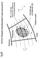
- the flow machine at least a blade of a stator row means for fluid removal on the bucket suction side in meridian flow direction not punctually, but over a defined area are distributed and their meridian extension in Meridian flow lines or orthogonal direction to at least one of the annular channel walls (hub or housing) decreases towards (suction side, intensity variable fluid removal SIFE).
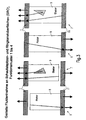
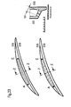
- Fig. 3 shows a greatly simplified representation of the invention Solution on four differently configured ones Blade rows, each having a rotor 6 and a stator 7, with the rotor blades 8 and Statorschaufeln 9 are provided.
- the reference numeral 1 is greatly simplified Representation of a housing or an outer shroud played.
- Reference numeral 11 denotes a rotor drum or an inside shroud. Shown is the suction side of the respective blade.
- stators On stators is one Suction-side, Intensity-Variable Fluid Suction Zone (SIFE) intended.
- SIFE Intensity-Variable Fluid Suction Zone
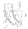
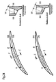
- FIG. 4 shows the basic concept according to the invention.
- Fig. 5 shows four different configurations of the invention
- the fluid flow machine This designates that Reference numeral 10 to flow from left to right Ring channel, with the reference numeral 13 is the machine axis represented by which a rotor drum (hub) 11 rotates.
- a rotor drum (hub) 11 rotates.
- FIGS. 5B and 5D If another rotor drum (hub) 12 is provided.
- the rotors, Stators and the pilot wheel are each labeled in FIG. 5, it is in each case a blade in a schematic way shown.
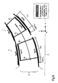
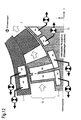
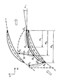
- FIG. 6 shows the definition of the blade tip and annular channel surfaces (SRO). There are total three types shown. It is again a simplified one Rotor 6 and a stator 7 shown in the annular channel 10 between a housing 1 and a hub (rotor drum) 11 is arranged are.
- SRO Type A The surfaces are on the hub or housing contour the annular channel is formed with a fixed connection to the blade, as in the case of platforms, shrouds, bliskund Bling configurations occur between the trailing edge plane HK and a level that is 25% of the meridional Blade chord length Cm is located in front of the leading edge plane VK.
- SRO, type B The surfaces are on hub or housing contours of the annular channel 10 in the region of free blade ends (above rotors without shroud or underneath stators without Shroud) between the trailing edge plane HK and a plane, which prefers 25% of the meridional blade chord length Cm the leading edge plane VK is formed.
- SRO, type C The surfaces are on blades at their free Bucket ends formed, the hub or the housing contour of the annular channel 10 facing (tip end faces of Shovel).
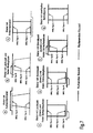
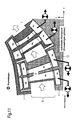
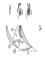
- Fig. 7 shows different embodiments of blade rows the flow machine according to the invention with a Identification of recurring elements SRO, type A, type B, type C.
- the embodiments show following:
- FIG. 7 a shows an assembly consisting of a rotor drum, with a plurality of rotor blades rotating with the drum, one surrounding the rotor blades on the outer circumference and co-rotating shroud and one of the rotating parts surrounding and resting housing.
- Fig. 7b shows a variant with an assembly consisting from a rotor drum, several rotating with the drum Rotor blades with free outer ends, as well as one rotating Parts surrounding and stationary housing.
- Fig. 7c shows an assembly consisting of a stationary Outer housing, a plurality of stator blades connected to the outer housing, and one of the stator blades on the inner Scope worn shroud and one within the dormant Components rotating rotor drum.
- Fig. 7d shows an assembly consisting of a stationary Outer housing, a plurality of stator blades connected to the outer housing with free inner ends and one inside the stationary components rotating rotor drum.
- FIG. 7e an assembly can be seen, which consists of a resting outer casing, several connected to the outer casing Stator blades with free inner ends, and one inside the stator blade row is stationary inner housing.
- FIG. 7f shows an assembly consisting of a stationary one Inner housing, several stator blades connected to the inner housing with free outer ends, and a stator blade row surrounding outer casing.
- Fig. 7g illustrates an assembly, which consists of a stationary Inner and outer housing consists, as well as several with the Inner and outer housing connected stator blades.
- the fluid is either at free flow or but with the help of at least one in the flow path Throttle body, which can be adjustable or adjustable, from the annular channel in the area of the blade row concerned led out.
- Throttle body which can be adjustable or adjustable, from the annular channel in the area of the blade row concerned led out.
- This removal of the fluid takes place with the Target, either the fluid completely from the fluid flow machine or from the turbomachine enclosing Complete system (conveyor system, gas turbine or engine) to remove, or the fluid the annular channel of the fluid flow machine or the entire system to be fed again.
- the necessary elements of the flow path can according to the invention as a simple cavity, as an annulus, as a pipeline, as a channel, as a nozzle or as a diffuser of any cross-sectional shape be configured and according to the invention in the following summarized under the term "chamber".
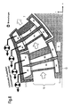
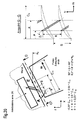
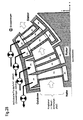
- FIGS. 8 to 10 show different design variants the invention with configurations in which discharge chambers (AK), bucket inner chambers (SK) and hub chambers (NK) are provided.
- AK discharge chambers
- SK bucket inner chambers
- NK hub chambers
- FIGS. 8 to 10 show design variants, in which the individual rows of blades each at least a chamber is assigned on or in the housing, through the fluid is removed from the blade row (discharge chamber AK).
- discharge chamber AK For the Case, that at least one more chamber inside at least a scoop exists that extends beyond the entirety or only parts of the blade height extends (blade inner chamber SK), each discharge chamber AK with at least one blade inner chamber SK communicate and receive fluid from there.
- Does the blade have a free end with radial gap at the Hub or does not have the blade over the entire blade height reaching bucket inner chamber, can be used for fluid removal at the hub also at least one discharge chamber or exist in the hub outside the ring channel.
- Abfarhuntn and hub chambers extend over the whole or only parts of the machine scope.
- the discharge chambers serve to guide the fluid away from the relevant one Blade row, wherein the blade inner chambers and the hub chambers Tools are to access the relevant Blade tip and ring channel surfaces (SRO) of the concerned Create blade row.
- SRO Blade tip and ring channel surfaces
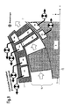
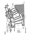
- FIGS. 8 to 10 While embodiments have been shown in FIGS. 8 to 10, in which at least one discharge chamber on or in the housing 11 to 13 show embodiments, in which at least one chamber on or in the Hub is arranged by the fluid from the blade row is removed (discharge chamber AK).
- discharge chamber AK In the event that at least another chamber exists inside at least one blade, spread over the entirety or just parts of the blade height extends (blade inner chamber SK), each discharge chamber AK with at least one blade inner chamber SK in conjunction stand and take fluid from there.
- blade has a free end with a radial gap on the housing or does not have the bucket over the entire bucket height reaching blade inner chamber SK, can be used for fluid removal at the housing also at least one discharge chamber on or in Housing outside the annular channel exist.
- the discharge chambers and the housing chambers extend over the entirety or only parts of the circumference of the fluid flow machine.
- the discharge chambers serve to guide the fluid from the relevant blade row.
- the bucket inner chambers and the Housing chambers are aids to access to relevant Blade tip and ring channel surfaces (SRO) in the area of the make relevant blade row.
- At least one blade tip and annular channel surface (SRO) on at least one of its Shovels and / or at least one of their the ring channel delimiting components at least one fluid removal device provided that a connection between the blade tip and annular channel surface (SRO) and a discharge chamber AK, a blade inner chamber SK, a secondary chamber NK or one Housing chamber GK manufactures.
- the structural design of the Fluid removal device is made by mechanical, chemical or thermal material removal methods on which the blade tips and annular channel surface (SRO) forming component.
- SRO Ring Channel Surfaces
- the fluid sampling device on blade tip and Ring channel surfaces (SRO) of type A are configurations of Slots or functionally similar replacement elements in the front Part of the scoop passage shown.
- Individual slots (resp. Replacement elements) can different discharge, housing or Be assigned hub chambers. This results in the following:
- the track F1-F2 as well as the track F6-F7, one tangential extension of the profile skeleton line SKL against the Flow direction.
- the route F1-F7 is 25% of the meridional Chord length (0.25 * Cm) in front of the leading edge plane.
- the distance F2-F3 is interposed by the suction side contour SS Given leading edge VK and trailing edge HK.
- the distance F3-F4 runs in the trailing edge plane from the profile to a Point at 20% of the outlet side blade pitch (0.2 * S) in the direction of the pressure side of the adjacent profile.
- the route F5-F6 is through a part of the print page contour DS between the leading edge VK and one by 30% of meridional chord length in the blade passage Point given.
- a number of at least 2 slots forms a special arrangement that is approximately orthogonal to the course aligns the expected boundary layer flow.
- the concept starts from one oriented along the suction side SS Slit that reaches to the trailing edge, but with rising Number of other slots provided is shorter. Further Slits are all the stronger against the meridian flow direction m inclined, the closer they are to the entrance of the blade channel lie. All slots are defined by a starting point, an end point and an angle for the initial to auxiliary end reaching auxiliary line.
- the starting points are on a baseline, either through the Suction side contour itself or one on the suction side contour given oriented line, which is in the circumferential direction u but at no point further than 20% of the outlet side Blade spacing (0.2 * S) away from it.
- the location all starting points is through the baseline and one defined meridional distance to the trailing edge plane.
- alpha (i) alpha1 + (i-1) * (110 ° - alpha1) / (N - 1).
- Alpha1 is set here by the fact that both Start and end point of the slot with the number 1 on lie the baseline. For alpha (i) there is a tolerance of +/- 20 °.
- Figs. 18 to 21 show embodiments of the fluid sampling device on blade tip and ring channel surfaces (SRO) Type B, in which a configuration of slots or functionally similar replacement elements in the front part of the free blade end is provided. Individual slots (resp. Replacement elements) of the configuration can be different discharge chambers be assigned.
- SRO blade tip and ring channel surfaces
- Individual slots (resp. Replacement elements) of the configuration can be different discharge chambers be assigned.
- SRO blade tip and ring channel surfaces
- FIG. 20 shows a Fluid sampling device of type B with a staggered Slot arrangement
- Fig. 21 shows a design variant a fluid removal device of the type B shows, in which a slot is replaced by rows of holes.
- Figs. 18 to 21 show the following details of inventive solution:
- the starting point A is at a meridional distance a from the vane leading edge viewed at the blade end.
- the End point E is at a meridional distance e from the blade leading edge considered at the blade end.
- the slots have the width b, which is between 0 and 3% of the meridional tendon length Cm can vary.
- d around which the slits are separated from one another: 0 ⁇ d ⁇ e-a- (N * b).
- the course of a slot can be in the circumferential direction u be interrupted by a certain amount. This is true for purely circumferential as well as oblique (i.e., with a meridian direction component) running slots.
- the circumferential length V individual interruptions and the circumferential length U individual remaining slot sections can along the Slotverlaufes be different, the sums of the remaining Slot lengths and the interruption lengths, however, must in a ratio of less than 50 (sum U / sum V ⁇ 50).
- the slots have angular, chamfered or rounded Surface edges. They have one at their ends angular shape or a round (slot-like) conclusion.
- the slots lead perpendicular or obliquely to Ringkanaloberf kaue through the wall material in a discharge chamber AK and take a straight or curved course.
- Fig. 20 is the Slot course interrupted periodically and the slot sections are arranged staggered.
- the slot portions around the angle beta which are between 30 ° and 90 ° can be tilted against the meridional flow direction (30 ° ⁇ beta ⁇ 90 °).
- the slot section does not have to be rectilinear but can be curved one or more times.
- the slot In the meridian plane (x, r) the slot can be viewed at angle alpha to the meridional flow direction m be inclined. For special requirements may have a pronounced Schlitzordtechnik, so that the area of alpha already along a slot section partially or fully exhausted.
- Fig. 21 it can be replaced by at least one slot section of the overall configuration, make a row of holes, see Fig. 21.
- the hole diameter is subject to the same limitations like the slot width b.
- Figs. 22 to 24 show embodiments of the invention Fluid sampling device on Schaufelspitzen- and annular channel surfaces (SRO) of type C, in which one along the Bucket tip attached slot or functionally similar Replacement elements are provided. Slots or spare elements can be assigned to different blade chambers.
- SRO Schaufelspitzen- and annular channel surfaces
- Fig. 22 shows a fluid removal device on a Blade tip and ring channel surface (SRO) type C with at least one slot or spare elements.
- SRO blade tip and ring channel surface
- the blade tip is either Conventional (approximately rectangular) or executed with a paragraph, its specific shape by the sizes a, b, c and phi is given.
- the quantities a, b, c and phi can be found in the specified limits with the considered profile depth to change.
- the starting point A of the slot arrangement lies between the leading edge VK and a tread depth of 30 % of chord length C.
- the end point E lies between the starting point A and one Profile depth of 80% of the chord length C.
- the width W of Slot arrangement is variable and takes the maximum ever current profile depth reduced by the paragraph foot width b Profile thickness D an (0 ⁇ W ⁇ D-b).
- the slot has angular, chamfered or rounded surface edges. You own Start and end point a square shape or a round (slot-like) degree.
- the slots lead vertically or obliquely to the blade tip surface through the wall material in a blade chamber SK.
- Figs. 25 to 27 show embodiments of the invention Device for suction side, intensity variable Fluid removal (SIFE) on one stator row.
- SIFE intensity variable Fluid removal
- the fluid removal takes place through a number of openings, be assigned to the different blade inner chambers can.
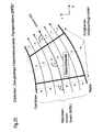
- a stator blade row of the turbomachine is in the coordinate system formed from the axial and radial directions (x, r).
- FIG. 26 shows an exemplary embodiment of the invention Device for SIFE.
- the of the device occupied zone of the suction side is surrounded by the envelope all interconnect openings are described (device envelope VE).
- the device is such that along a certain meridional streamline, the maximum meridian extent s (x) is present. According to the transition results to adjacent meridian flow lines one toward the housing and in the direction of the hub gradually or continuously decreasing meridian extent. From streamline to Streamline therefore applies:
- the device consists of a Number of straight, parallel slots.
- everyone can Slit curved one or more times, constant or have variable width in its longitudinal direction, and at the beginning and end of a square shape or a round (slot-like) completion possess.
- Between slot and Meridianstromline can any inclination angle delta available.
- the slots lead vertically or diagonally to Suction side surface through the wall material in a blade inner chamber SK.
- a modified form occurs - with the same rules in terms the arrangement and the course on the suction side surface and the nature of the surface edges and Orientation in the suction side wall - to the place at least a slot a single or multi-row formation of holes.
- another modified form is - at the same Rules regarding the arrangement and the course of the Suction side surface - at least one slot as a backflow inlet formed, characterized in that fluid under at most 30 ° to the suction side surface is removed (see illustration in Fig. 17, right).
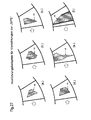
- Fig. 27 shows different embodiments of a Device for SIFE. In detail, show the embodiments following:
- Fig. 27a shows a stator assembly suitable for implementation the meridian current line orthogonal variation according to the invention the fluid intake intensity on the suction side of a formation consisting of 2 slots and a row of holes.
- the device covered according to the invention only a part of the suction side and is arranged in this application example in its central area.
- the composite of slots and holes is through the Device enveloping VE surrounded and marked. It is obvious that the meridian extent of the device here both in the direction of the housing and in the direction of the hub decreases continuously.
- FIG. 27b shows a modified according to the invention compared to FIG. 27a Stator assembly, in which the slot and hole elements take a different order and the number of elements is increased.
- Fig. 27c shows a stator assembly according to the invention, the on the suction side has a formation of 3 slots.
- the Device is primarily in this application example the housing looking.
- the composite of the openings is through the device envelope VE surrounded and marked. It is obvious that the Meridianerstreckung the device here in the direction gradually falls to zero and towards the hub decreases continuously.
- Fig. 27d shows a stator assembly on the suction side has a formation of holes.
- the device is in this application example arranged in the central region of the suction side.
- the device envelope indicates that the Meridian extension of the device in this application example both in the direction of the housing and in the direction of Hub decreases continuously.
- Fig. 27e shows a stator assembly on the suction side has a formation of 3 slots.
- the device is lying in this application example on the housing.
- the device envelope lets us see that the meridian extension of the device here in the direction of the hub decreases continuously.
- Fig. 27f shows a stator assembly mounted on the suction side has a formation of 2 storage entrances.
- the device lies in this application example at the hub.
- the device envelope lets us see that the meridian extension the device here in the direction of the housing continuously decreases.
- Blade row of the turbomachine both a chamber system for fluid removal and subsequent removal of the Shovel side in an area outside the ring channel as also a not further to be determined chamber system for pre-accession from fluid to the blade side and subsequent delivery in the annular channel to surfaces in front or inside this blade row.
- fluid removal and fluid supply combine at and same blade of a rotor or stator, or are at different Blades of the same rotor or blade row intended.
- FIGS. 28 and 29 show by way of example some possible variants vane sides with the corresponding bifunctionality on the same shovel.
Landscapes
- Engineering & Computer Science (AREA)
- Mechanical Engineering (AREA)
- General Engineering & Computer Science (AREA)
- Physics & Mathematics (AREA)
- Fluid Mechanics (AREA)
- Chemical & Material Sciences (AREA)
- Combustion & Propulsion (AREA)
- Structures Of Non-Positive Displacement Pumps (AREA)
Abstract
Description
Merchant et al.: Aerodynamic Design and Analysis of a High Pressure Ratio Aspirated Compressor Stage, ASME Paper 2000-GT-619.
- Fig. 1
- eine schematische Darstellung des Standes der Technik,
- Fig. 2
- eine abgewandelte Darstellung eines weiteren aus dem Stand der Technik bekannten Ausführungsbeispiels,
- Fig. 3
- eine schematische Darstellung des erfindungsgemäßen Grundkonzepts,
- Fig. 4
- eine weitere Darstellung unterschiedlicher erfindungsgemäßer Varianten,
- Fig. 5
- verschiedene Varianten und Konfigurationen der erfindungsgemäßen Strömungsarbeitsmaschine,
- Fig. 6
- eine Darstellung zur erfindungsgemäßen Definition des Begriffs SRO,
- Fig. 7
- eine weitere Darstellung zur erfindungsgemäßen Definition von SRO,
- Fig. 8 bis 10
- unterschiedliche Ausgestaltungsformen von Kammern zur Abführung des Fluids vornehmlich vom Gehäuse aus,
- Fig. 11 bis 13
- Ausgestaltungsvarianten analog Fig. 8 bis 10 mit Kammern zur Abführung des Fluids vornehmlich von der Nabe aus,
- Fig. 14 bis 17
- erfindungsgemäße Ausführungsvarianten einer Fluidentnahmevorrichtung an Schaufelspitzen und Ringkanaloberflächen (SRO) des Typs A,
- Fig. 18 bis 21
- erfindungsgemäße Ausführungsvarianten der Fluidentnahmevorrichtung an Schaufelspitzen- und Ringkanaloberflächen (SRO) des Typs B,
- Fig. 22 bis 24
- erfindungsgemäße Ausführungsvarianten einer Fluidentnahmevorrichtung an Schaufelspitzen- und Ringkanaloberflächen des Typs C, und
- Fig. 25 bis 27
- erfindungsgemäße Vorrichtungen zur saugseitigen, intensitätsvariablen Fluidentnahme (SIFE),
- Fig. 28 bis 29
- unterschiedliche Ausgestaltungsformen von Kammern zur gleichzeitigen Abführung und Zuführung von Fluid an derselben Schaufelreihe (Bifunktionalität).
- 1
- Gehäuse
- 2
- Schaufel
- 3
- Schlitz
- 4
- Schlitz
- 5
- Stator
- 6
- Rotor
- 7
- Stator
- 8
- Rotorschaufel
- 9
- Statorschaufel
- 10
- Ringkanal
- 11
- Rotortrommel (Nabe)
- 12
- Rotortrommel (Nabe)
- 13
- Maschinenachse
Claims (18)
- Strömungsarbeitsmaschine mit zumindest einem Rotor (6), der mehrere an einer rotierenden Welle befestigte Rotorschaufeln (8) umfasst sowie mit einem Gehäuse (1), welches unter Durchströmung vom Rotor (6) von einem Fluid durchströmt wird, dadurch gekennzeichnet, dass Mittel zur Entnahme von Fluid an mindestens einer Schaufel (8, 9) einer Schaufelreihe des Rotors (6) an nicht-achsensymmetrisch angeordneten, aerodynamisch kritischen Orten auf Schaufelspitzen- und Ringkanaloberflächen (SRO) vorgesehen sind.
- Strömungsarbeitsmaschine nach Anspruch 1, dadurch gekennzeichnet, dass zumindestens ein Stator (7) vorgesehen ist, der mit feststehenden Statorschaufeln (9) versehen ist und vom Fluid durchströmt wird und dass die Mittel zur Entnahme von Fluid am Rotor (6) oder am Stator (7) an nicht achsensymmetrisch angeordneten, aerodynamisch kritischen Orten auf Schaufelspitzen- und Ringkanaloberflächen (SRO) vorgesehen sind.
- Strömungsarbeitsmaschine nach Anspruch 2, dadurch gekennzeichnet, dass an mindestens einer Schaufel (9) einer Schaufelreihe des Stators (7) mindestens eine Vorrichtung zur saugseitigen, intensitätsvariablen Fluidentnahme (SI-FE) vorgesehen ist.
- Strömungsarbeitsmaschine nach einem der Ansprüche 1 bis 3, dadurch gekennzeichnet, dass die Schaufelspitzen- und Ringkanaloberflächen (SRO) in Form von Oberflächen an Naben- oder Gehäusekonturen des Ringkanals mit fester Verbindung zur Schaufel zwischen der Hinterkantenebene HK und einer Ebene, die sich 25 % der meridionalen Schaufelsehnenlänge Cm vor der Vorderkantenebene VK befindet, ausgebildet sind.
- Strömungsarbeitsmaschine nach einem der Ansprüche 1 bis 3, dadurch gekennzeichnet, dass die Schaufelspitzen- und Ringkanaloberflächen (SRO) in Form von Oberflächen an Naben- oder Gehäusekonturen des Ringkanals im Bereich freier Schaufelenden zwischen der Hinterkantenebene HK und einer Ebene, die sich 25 % der meridionalen Schaufelsehnenlänge Cm vor der Vorderkantenebene VK befindet, ausgebildet sind.
- Strömungsarbeitsmaschine nach einem der Ansprüche 1 bis 3, dadurch gekennzeichnet, dass die Schaufelspitzen- und Ringkanaloberflächen (SRO) der Schaufel an freien Schaufelenden, die der Naben- oder der Gehäusekontur des Ringkanals zugewandt sind, ausgebildet sind.
- Strömungsarbeitsmaschine nach einem der Ansprüche 2 bis 6, dadurch gekennzeichnet, dass an zumindest einer Schaufel (9) einer Statorreihe (7) Mittel zur Fluidentnahme vorgesehen sind, die auf der Schaufelsaugseite in Meridianströmungsrichtung nicht punktuell, sondern über einen definierten Bereich verteilt angelegt sind.
- Strömungsarbeitsmaschine nach Anspruch 7, dadurch gekennzeichnet, dass die Mittel so angeordnet sind, dass deren Meridianerstreckung in meridianstromlinienorthogonaler Richtung zu wenigstens einer der Ringkanalwände (Nabe 11 oder Gehäuse 1) hin abnimmt (saugseitige, intensitätsvariable Fluidentnahme SIFE).
- Strömungsarbeitsmaschine nach einem der Ansprüche 1 bis 8, dadurch gekennzeichnet, dass das Fluid über Strömungswege an der Peripherie des Ringkanals abgeführt wird.
- Strömungsarbeitsmaschine nach einem der Ansprüche 1 bis 8, dadurch gekennzeichnet, dass das Fluid über Strömungswege innerhalb der Schaufel und/oder ihrer umgebenden Bauteile abgeführt wird.
- Strömungsarbeitsmaschine nach Anspruch 9 und 10, dadurch gekennzeichnet, dass das Fluid bei freier Strömung abgeführt wird.
- Strömungsarbeitsmaschine nach Anspruch 9 und 10, dadurch gekennzeichnet, dass das Fluid mittels mindestens eines im Strömungsweg angeordneten Drosselorgans vom Ringkanal abgeleitet wird.
- Strömungsarbeitsmaschine nach einem der Ansprüche 1 bis 12, dadurch gekennzeichnet, dass das Fluid von der Strömungsarbeitsmaschine gänzlich abgeführt wird.
- Strömungsarbeitsmaschine nach einem der Ansprüche 1 bis 13, dadurch gekennzeichnet, dass das Fluid wieder der Strömungsarbeitsmaschine rückgeführt wird.
- Strömungsarbeitsmaschine nach einem der Ansprüche 1 bis 14, dadurch gekennzeichnet, dass das Fluid durch zumindest einen Schlitz abgeleitet wird.
- Strömungsarbeitsmaschine nach einem der Ansprüche 1 bis 14, dadurch gekennzeichnet, dass das Fluid durch zumindest eine Reihe von lochartigen Ausnehmungen abgeleitet wird.
- Strömungsarbeitsmaschine nach einem der Ansprüche 1 bis 14, dadurch gekennzeichnet, dass das Fluid durch zumindest einen Staueinlauf abgeleitet wird.
- Strömungsarbeitsmaschine nach einem der Ansprüche 1 bis 17, dadurch gekennzeichnet, dass neben den erfindungsgemäßen Mitteln zur Fluidentnahme gleichzeitig Mittel zur Fluidzufuhr vor oder innerhalb des beschaufelten Raumes derselben Schaufelbereiche des Rotors oder des Stators vorgesehen sind.
Priority Applications (3)
| Application Number | Priority Date | Filing Date | Title |
|---|---|---|---|
| EP10008713A EP2249045A3 (de) | 2003-11-26 | 2004-10-06 | Strömungsarbeitsmaschine mit Fluidentnahme |
| EP10008711A EP2249043B1 (de) | 2003-11-26 | 2004-10-06 | Strömungsarbeitsmaschine mit Fluidentnahme |
| EP10008712.1A EP2249044B1 (de) | 2003-11-26 | 2004-10-06 | Strömungsarbeitsmaschine mit Fluidentnahme |
Applications Claiming Priority (2)
| Application Number | Priority Date | Filing Date | Title |
|---|---|---|---|
| DE10355240A DE10355240A1 (de) | 2003-11-26 | 2003-11-26 | Strömungsarbeitsmaschine mit Fluidentnahme |
| DE10355240 | 2003-11-26 |
Related Child Applications (3)
| Application Number | Title | Priority Date | Filing Date |
|---|---|---|---|
| EP10008711.3 Division-Into | 2010-08-20 | ||
| EP10008713.9 Division-Into | 2010-08-20 | ||
| EP10008712.1 Division-Into | 2010-08-20 |
Publications (3)
| Publication Number | Publication Date |
|---|---|
| EP1536146A2 true EP1536146A2 (de) | 2005-06-01 |
| EP1536146A3 EP1536146A3 (de) | 2008-04-02 |
| EP1536146B1 EP1536146B1 (de) | 2010-12-08 |
Family
ID=34442295
Family Applications (4)
| Application Number | Title | Priority Date | Filing Date |
|---|---|---|---|
| EP04023822A Expired - Lifetime EP1536146B1 (de) | 2003-11-26 | 2004-10-06 | Strömungsarbeitsmaschine mit Fluidentnahme |
| EP10008711A Expired - Lifetime EP2249043B1 (de) | 2003-11-26 | 2004-10-06 | Strömungsarbeitsmaschine mit Fluidentnahme |
| EP10008712.1A Expired - Lifetime EP2249044B1 (de) | 2003-11-26 | 2004-10-06 | Strömungsarbeitsmaschine mit Fluidentnahme |
| EP10008713A Withdrawn EP2249045A3 (de) | 2003-11-26 | 2004-10-06 | Strömungsarbeitsmaschine mit Fluidentnahme |
Family Applications After (3)
| Application Number | Title | Priority Date | Filing Date |
|---|---|---|---|
| EP10008711A Expired - Lifetime EP2249043B1 (de) | 2003-11-26 | 2004-10-06 | Strömungsarbeitsmaschine mit Fluidentnahme |
| EP10008712.1A Expired - Lifetime EP2249044B1 (de) | 2003-11-26 | 2004-10-06 | Strömungsarbeitsmaschine mit Fluidentnahme |
| EP10008713A Withdrawn EP2249045A3 (de) | 2003-11-26 | 2004-10-06 | Strömungsarbeitsmaschine mit Fluidentnahme |
Country Status (3)
| Country | Link |
|---|---|
| US (1) | US7364404B2 (de) |
| EP (4) | EP1536146B1 (de) |
| DE (2) | DE10355240A1 (de) |
Cited By (6)
| Publication number | Priority date | Publication date | Assignee | Title |
|---|---|---|---|---|
| WO2009062793A1 (en) * | 2007-11-12 | 2009-05-22 | Siemens Aktiengesellschaft | Air bleed in compressor with variable guide vanes |
| EP1707744A3 (de) * | 2005-03-07 | 2009-05-27 | General Electric Company | Statorschaufel mit innerem und äusserem Deckband |
| WO2011157398A3 (de) * | 2010-06-14 | 2013-04-04 | Rolls-Royce Deuschland Ltd. & Co. Kg | Turbomaschine mit geräuschreduzierung |
| EP2180193A3 (de) * | 2008-10-21 | 2014-05-07 | Rolls-Royce Deutschland Ltd & Co KG | Strömungsarbeitsmaschine mit saugseitennaher Randenergetisierung |
| EP3418494A1 (de) * | 2017-06-23 | 2018-12-26 | Rolls-Royce plc | Sekundärströmungssteuerung |
| EP2138727B1 (de) * | 2008-06-23 | 2019-01-02 | Rolls-Royce Deutschland Ltd & Co KG | Schaufeldeckband mit Durchlass |
Families Citing this family (26)
| Publication number | Priority date | Publication date | Assignee | Title |
|---|---|---|---|---|
| DE102004043036A1 (de) * | 2004-09-06 | 2006-03-09 | Rolls-Royce Deutschland Ltd & Co Kg | Strömungsarbeitsmaschine mit Fluidentnahme |
| DE102004055439A1 (de) * | 2004-11-17 | 2006-05-24 | Rolls-Royce Deutschland Ltd & Co Kg | Strömungsarbeitsmaschine mit dynamischer Strömungsbeeinflussung |
| US7784261B2 (en) * | 2006-05-25 | 2010-08-31 | Siemens Energy, Inc. | Combined cycle power plant |
| US7661924B2 (en) * | 2007-03-28 | 2010-02-16 | General Electric Company | Method and apparatus for assembling turbine engines |
| DE102007037924A1 (de) * | 2007-08-10 | 2009-02-12 | Rolls-Royce Deutschland Ltd & Co Kg | Strömungsarbeitsmaschine mit Ringkanalwandausnehmung |
| DE102008004834A1 (de) * | 2008-01-17 | 2009-07-23 | Rolls-Royce Deutschland Ltd & Co Kg | Radialverdichter mit Abnahme und Rückführung von Luft am Gehäuse |
| DE102008005163B4 (de) * | 2008-01-19 | 2009-12-03 | Deutsches Zentrum für Luft- und Raumfahrt e.V. | Flugtriebwerk |
| DE102008011644A1 (de) * | 2008-02-28 | 2009-09-03 | Rolls-Royce Deutschland Ltd & Co Kg | Gehäusestrukturierung für Axialverdichter im Nabenbereich |
| DE102008019603A1 (de) * | 2008-04-18 | 2009-10-22 | Rolls-Royce Deutschland Ltd & Co Kg | Strömungsmaschine mit schaufelreiheninterner Fluid-Rückführung |
| DE102008031982A1 (de) * | 2008-07-07 | 2010-01-14 | Rolls-Royce Deutschland Ltd & Co Kg | Strömungsarbeitsmaschine mit Nut an einem Laufspalt eines Schaufelendes |
| DE102008037154A1 (de) | 2008-08-08 | 2010-02-11 | Rolls-Royce Deutschland Ltd & Co Kg | Strömungsarbeitsmaschine |
| DE102008052101A1 (de) * | 2008-10-20 | 2010-04-22 | Rolls-Royce Deutschland Ltd & Co Kg | Verdichter für eine Gasturbine |
| DE102008060424A1 (de) * | 2008-12-04 | 2010-06-10 | Rolls-Royce Deutschland Ltd & Co Kg | Strömungsmaschine mit Seitenwand-Grenzschicht-Barriere |
| US20110116934A1 (en) * | 2009-11-16 | 2011-05-19 | Meng Sen Y | Pumping element design |
| US9816522B2 (en) * | 2010-02-09 | 2017-11-14 | Ihi Corporation | Centrifugal compressor having an asymmetric self-recirculating casing treatment |
| US9151297B2 (en) | 2010-02-09 | 2015-10-06 | Ihi Corporation | Centrifugal compressor having an asymmetric self-recirculating casing treatment |
| JP5430685B2 (ja) | 2010-02-09 | 2014-03-05 | 株式会社Ihi | 非軸対称自己循環ケーシングトリートメントを有する遠心圧縮機 |
| EP2535596B1 (de) | 2010-02-09 | 2018-06-20 | IHI Corporation | Zentrifugalverdichter mit einer asymmetrischen selbst-rückzirkulierenden gehäusebearbeitung |
| US9181814B2 (en) * | 2010-11-24 | 2015-11-10 | United Technology Corporation | Turbine engine compressor stator |
| US9528391B2 (en) | 2012-07-17 | 2016-12-27 | United Technologies Corporation | Gas turbine engine outer case with contoured bleed boss |
| GB2531029B (en) * | 2014-10-07 | 2020-11-18 | Cummins Ltd | Compressor and turbocharger |
| EP3037674A1 (de) * | 2014-12-22 | 2016-06-29 | Alstom Technology Ltd | Motor und Verfahren zum Betrieb des besagten Motors |
| BE1024743B1 (fr) * | 2016-11-21 | 2018-06-21 | Safran Aero Boosters Sa | Compresseur basse pression de turbomachine axiale |
| FR3082554B1 (fr) | 2018-06-15 | 2021-06-04 | Safran Aircraft Engines | Aube de turbine comprenant un systeme passif de reduction des phenomenes tourbillonaires dans un flux d'air qui la parcourt |
| CN117588444B (zh) * | 2023-10-23 | 2025-08-05 | 西北工业大学 | 一种叶片开槽与自循环处理机匣耦合的流动控制方法及结构 |
| JP2025132451A (ja) * | 2024-02-29 | 2025-09-10 | 三菱重工業株式会社 | 圧縮機静翼、これを備える圧縮機、及びガスタービン設備 |
Citations (4)
| Publication number | Priority date | Publication date | Assignee | Title |
|---|---|---|---|---|
| DE722424C (de) | 1940-04-16 | 1942-07-09 | Friedrich Schicht | Gleichdruck-Geblaese oder Gleichdruck-Pumpe |
| US3414188A (en) | 1966-11-25 | 1968-12-03 | American Radiator & Standard | Fan having hollow blades |
| US3846038A (en) | 1971-12-27 | 1974-11-05 | Onera (Off Nat Aerospatiale) | Fixed blading of axial compressors |
| US5762470A (en) | 1993-03-11 | 1998-06-09 | Central Institute Of Aviation Motors (Ciam) | Anti-stall tip treatment means |
Family Cites Families (50)
| Publication number | Priority date | Publication date | Assignee | Title |
|---|---|---|---|---|
| GB479427A (en) * | 1935-05-31 | 1938-01-31 | Gyoergy Jendrassik | Improvements in rotary compressors |
| CH204331A (de) * | 1937-02-24 | 1939-04-30 | Rheinmetall Borsig Ag | Einrichtung zur Verhinderung der Strahlablösung bei Turboverdichtern. |
| DE889506C (de) * | 1940-09-25 | 1953-09-10 | Versuchsanstalt Fuer Luftfahrt | Stroemungsmaschine mit Grenzschichtabsaugung |
| GB619722A (en) | 1946-12-20 | 1949-03-14 | English Electric Co Ltd | Improvements in and relating to boundary layer control in fluid conduits |
| US2870957A (en) | 1947-12-26 | 1959-01-27 | Edward A Stalker | Compressors |
| US2738921A (en) * | 1950-11-22 | 1956-03-20 | United Aircraft Corp | Boundary layer control apparatus for compressors |
| US2720356A (en) | 1952-06-12 | 1955-10-11 | John R Erwin | Continuous boundary layer control in compressors |
| US2933238A (en) * | 1954-06-24 | 1960-04-19 | Edward A Stalker | Axial flow compressors incorporating boundary layer control |
| GB799675A (en) | 1955-10-13 | 1958-08-13 | Bristol Aeroengines Ltd | Improvements in or relating to axial flow gas compressors and turbines |
| US3066912A (en) * | 1961-03-28 | 1962-12-04 | Gen Electric | Turbine erosion protective device |
| US3348622A (en) * | 1962-12-24 | 1967-10-24 | Papst Hermann | Boundary layer control |
| CH437614A (de) | 1963-07-02 | 1967-11-30 | Moravec Zdenek | Strömungsmaschine mit verminderter Geräuscherzeugung |
| GB1085227A (en) * | 1963-07-26 | 1967-09-27 | Rolls Royce | Improvements in or relating to gas turbine engines |
| GB987625A (en) | 1963-10-14 | 1965-03-31 | Rolls Royce | Improvements in or relating to axial flow compressors, for example for aircraft gas turbine engines |
| DE1301432B (de) * | 1965-12-16 | 1969-08-21 | Bbc Brown Boveri & Cie | Anordnung zur Vergroesserung des stabilen Arbeitsbereiches von ein- und mehrstufigenAxialverdichtern, Geblaesen, Ventilatoren und Pumpen mittels Grenzschichtbeseitigung |
| US3365124A (en) * | 1966-02-21 | 1968-01-23 | Gen Electric | Compressor structure |
| FR1521512A (fr) * | 1967-03-07 | 1968-04-19 | Rateau Soc | Aube de compresseur axial |
| US3572960A (en) * | 1969-01-02 | 1971-03-30 | Gen Electric | Reduction of sound in gas turbine engines |
| DE1938132A1 (de) * | 1969-07-26 | 1971-01-28 | Daimler Benz Ag | Leitschaufeln von Axialverdichtern |
| GB1291943A (en) * | 1970-02-11 | 1972-10-04 | Secr Defence | Improvements in or relating to ducted fans |
| FR2248732A5 (de) * | 1973-10-23 | 1975-05-16 | Onera (Off Nat Aerospatiale) | |
| US4155680A (en) * | 1977-02-14 | 1979-05-22 | General Electric Company | Compressor protection means |
| DE2834822C2 (de) * | 1978-08-09 | 1981-09-17 | MTU Motoren- und Turbinen-Union München GmbH, 8000 München | Einrichtung zur Verdichterluftentnahme bei Gasturbinentriebwerken |
| FR2491549B1 (fr) * | 1980-10-08 | 1985-07-05 | Snecma | Dispositif de refroidissement d'une turbine a gaz, par prelevement d'air au niveau du compresseur |
| DE3407945A1 (de) | 1984-03-03 | 1985-09-05 | MTU Motoren- und Turbinen-Union München GmbH, 8000 München | Verfahren und mittel zur vermeidung der entstehung von titanfeuer |
| US5059093A (en) * | 1990-06-07 | 1991-10-22 | United Technologies Corporation | Compressor bleed port |
| US5203162A (en) * | 1990-09-12 | 1993-04-20 | United Technologies Corporation | Compressor bleed manifold for a gas turbine engine |
| FR2666846B1 (fr) * | 1990-09-13 | 1992-10-16 | Alsthom Gec | Grille d'aubes pour turbomachine munie de fentes d'aspiration dans le plafond et/ou dans le plancher et turbomachine comportant ces grilles. |
| JPH04132899A (ja) * | 1990-09-25 | 1992-05-07 | Mitsubishi Heavy Ind Ltd | 軸流送風機 |
| KR100198721B1 (ko) * | 1991-01-30 | 1999-06-15 | 레비스 스테픈 이 | 개선된 케이스를 갖는 가스 터어빈 엔진 |
| US5327716A (en) * | 1992-06-10 | 1994-07-12 | General Electric Company | System and method for tailoring rotor tip bleed air |
| US5480284A (en) * | 1993-12-20 | 1996-01-02 | General Electric Company | Self bleeding rotor blade |
| US5562404A (en) | 1994-12-23 | 1996-10-08 | United Technologies Corporation | Vaned passage hub treatment for cantilever stator vanes |
| US5607284A (en) | 1994-12-29 | 1997-03-04 | United Technologies Corporation | Baffled passage casing treatment for compressor blades |
| US5762034A (en) * | 1996-01-16 | 1998-06-09 | Board Of Trustees Operating Michigan State University | Cooling fan shroud |
| US6004095A (en) * | 1996-06-10 | 1999-12-21 | Massachusetts Institute Of Technology | Reduction of turbomachinery noise |
| DE19632207A1 (de) * | 1996-08-09 | 1998-02-12 | Bmw Rolls Royce Gmbh | Verfahren zur Verhinderung der laminaren Grenzschicht-Ablösung an Turbomaschinen-Schaufeln |
| US5904470A (en) | 1997-01-13 | 1999-05-18 | Massachusetts Institute Of Technology | Counter-rotating compressors with control of boundary layers by fluid removal |
| US6109868A (en) * | 1998-12-07 | 2000-08-29 | General Electric Company | Reduced-length high flow interstage air extraction |
| US6574965B1 (en) * | 1998-12-23 | 2003-06-10 | United Technologies Corporation | Rotor tip bleed in gas turbine engines |
| US6302640B1 (en) * | 1999-11-10 | 2001-10-16 | Alliedsignal Inc. | Axial fan skip-stall |
| DE10135003C1 (de) * | 2001-07-18 | 2002-10-02 | Mtu Aero Engines Gmbh | Verdichtergehäusestruktur |
| US6585479B2 (en) * | 2001-08-14 | 2003-07-01 | United Technologies Corporation | Casing treatment for compressors |
| US6663346B2 (en) * | 2002-01-17 | 2003-12-16 | United Technologies Corporation | Compressor stator inner diameter platform bleed system |
| DE10233032A1 (de) * | 2002-07-20 | 2004-01-29 | Rolls-Royce Deutschland Ltd & Co Kg | Strömungsarbeitsmaschine mit integriertem Fluidzirkulationssystem |
| DE10330084B4 (de) | 2002-08-23 | 2010-06-10 | Mtu Aero Engines Gmbh | Rezirkulationsstruktur für Turboverdichter |
| ATE325939T1 (de) * | 2002-08-23 | 2006-06-15 | Mtu Aero Engines Gmbh | Rezirkulationsstruktur für turboverdichter |
| US7097414B2 (en) * | 2003-12-16 | 2006-08-29 | Pratt & Whitney Rocketdyne, Inc. | Inducer tip vortex suppressor |
| GB2413158B (en) * | 2004-04-13 | 2006-08-16 | Rolls Royce Plc | Flow control arrangement |
| DE102004030597A1 (de) * | 2004-06-24 | 2006-01-26 | Rolls-Royce Deutschland Ltd & Co Kg | Strömungsarbeitsmaschine mit Aussenradstrahlerzeugung am Stator |
-
2003
- 2003-11-26 DE DE10355240A patent/DE10355240A1/de not_active Withdrawn
-
2004
- 2004-10-06 EP EP04023822A patent/EP1536146B1/de not_active Expired - Lifetime
- 2004-10-06 EP EP10008711A patent/EP2249043B1/de not_active Expired - Lifetime
- 2004-10-06 EP EP10008712.1A patent/EP2249044B1/de not_active Expired - Lifetime
- 2004-10-06 DE DE502004011969T patent/DE502004011969D1/de not_active Expired - Lifetime
- 2004-10-06 EP EP10008713A patent/EP2249045A3/de not_active Withdrawn
- 2004-11-26 US US10/996,619 patent/US7364404B2/en not_active Expired - Fee Related
Patent Citations (4)
| Publication number | Priority date | Publication date | Assignee | Title |
|---|---|---|---|---|
| DE722424C (de) | 1940-04-16 | 1942-07-09 | Friedrich Schicht | Gleichdruck-Geblaese oder Gleichdruck-Pumpe |
| US3414188A (en) | 1966-11-25 | 1968-12-03 | American Radiator & Standard | Fan having hollow blades |
| US3846038A (en) | 1971-12-27 | 1974-11-05 | Onera (Off Nat Aerospatiale) | Fixed blading of axial compressors |
| US5762470A (en) | 1993-03-11 | 1998-06-09 | Central Institute Of Aviation Motors (Ciam) | Anti-stall tip treatment means |
Cited By (9)
| Publication number | Priority date | Publication date | Assignee | Title |
|---|---|---|---|---|
| EP1707744A3 (de) * | 2005-03-07 | 2009-05-27 | General Electric Company | Statorschaufel mit innerem und äusserem Deckband |
| WO2009062793A1 (en) * | 2007-11-12 | 2009-05-22 | Siemens Aktiengesellschaft | Air bleed in compressor with variable guide vanes |
| EP2138727B1 (de) * | 2008-06-23 | 2019-01-02 | Rolls-Royce Deutschland Ltd & Co KG | Schaufeldeckband mit Durchlass |
| EP2180193A3 (de) * | 2008-10-21 | 2014-05-07 | Rolls-Royce Deutschland Ltd & Co KG | Strömungsarbeitsmaschine mit saugseitennaher Randenergetisierung |
| US8834116B2 (en) | 2008-10-21 | 2014-09-16 | Rolls-Royce Deutschland Ltd & Co Kg | Fluid flow machine with peripheral energization near the suction side |
| WO2011157398A3 (de) * | 2010-06-14 | 2013-04-04 | Rolls-Royce Deuschland Ltd. & Co. Kg | Turbomaschine mit geräuschreduzierung |
| US9574452B2 (en) | 2010-06-14 | 2017-02-21 | Rolls-Royce Deutschland Ltd & Co Kg | Noise-reduced turbomachine |
| EP3418494A1 (de) * | 2017-06-23 | 2018-12-26 | Rolls-Royce plc | Sekundärströmungssteuerung |
| US10760427B2 (en) | 2017-06-23 | 2020-09-01 | Rolls-Royce Plc | Secondary flow control |
Also Published As
| Publication number | Publication date |
|---|---|
| EP2249043A3 (de) | 2011-06-22 |
| EP1536146A3 (de) | 2008-04-02 |
| US20050238483A1 (en) | 2005-10-27 |
| EP2249044B1 (de) | 2013-08-28 |
| EP2249044A2 (de) | 2010-11-10 |
| EP1536146B1 (de) | 2010-12-08 |
| EP2249043A2 (de) | 2010-11-10 |
| US7364404B2 (en) | 2008-04-29 |
| EP2249044A3 (de) | 2011-06-29 |
| DE10355240A1 (de) | 2005-07-07 |
| DE502004011969D1 (de) | 2011-01-20 |
| EP2249043B1 (de) | 2013-01-23 |
| EP2249045A3 (de) | 2011-06-29 |
| EP2249045A2 (de) | 2010-11-10 |
Similar Documents
| Publication | Publication Date | Title |
|---|---|---|
| EP1536146B1 (de) | Strömungsarbeitsmaschine mit Fluidentnahme | |
| EP2226509B1 (de) | Strömungsarbeitsmaschine mit Fluidzufuhr zur Grenzschichtbeeinflussung | |
| EP1659293B1 (de) | Strömungsmaschine | |
| DE60320537T2 (de) | Kompressor mit schaufelspitzeneinrichtung | |
| EP1382855B1 (de) | Strömungsarbeitsmaschine mit integriertem Fluidzirkulationssystem | |
| EP1609999B1 (de) | Strömungsarbeitsmaschine | |
| EP2110559B1 (de) | Strömungsmaschine mit Fluidrückfuhr zur Grenzschichtbeeinflussung | |
| EP2138727B1 (de) | Schaufeldeckband mit Durchlass | |
| EP1953344B1 (de) | Turbinenschaufel | |
| EP2108784B1 (de) | Strömungsmaschine mit Fluid-Injektorbaugruppe | |
| DE3685852T2 (de) | Turbinenmotor mit induziertem vordrall am kompressoreinlass. | |
| EP2180193B1 (de) | Strömungsarbeitsmaschine mit saugseitennaher Randenergetisierung | |
| EP3408503B1 (de) | Strömungsmaschine mit beschaufeltem diffusor | |
| EP2151582A2 (de) | Strömungsarbeitsmaschine | |
| EP2320030A1 (de) | Rotor mit Laufschaufel für eine axial durchströmte Turbomaschine | |
| EP1875045B1 (de) | Turbinenrad | |
| EP1998049A2 (de) | Strömungsarbeitsmaschinenschaufel mit Multi-Profil-Gestaltung | |
| EP2275643A2 (de) | Triebwerkschaufel mit überhöhter Vorderkantenbelastung | |
| EP1760321A2 (de) | Schaufel einer Strömungsarbeitsmaschine | |
| EP1512490B1 (de) | Reparaturverfahren für eine Schaufel einer Strömungsarbeitsmaschine |
Legal Events
| Date | Code | Title | Description |
|---|---|---|---|
| PUAI | Public reference made under article 153(3) epc to a published international application that has entered the european phase |
Free format text: ORIGINAL CODE: 0009012 |
|
| AK | Designated contracting states |
Kind code of ref document: A2 Designated state(s): AT BE BG CH CY CZ DE DK EE ES FI FR GB GR HU IE IT LI LU MC NL PL PT RO SE SI SK TR |
|
| AX | Request for extension of the european patent |
Extension state: AL HR LT LV MK |
|
| PUAL | Search report despatched |
Free format text: ORIGINAL CODE: 0009013 |
|
| AK | Designated contracting states |
Kind code of ref document: A3 Designated state(s): AT BE BG CH CY CZ DE DK EE ES FI FR GB GR HU IE IT LI LU MC NL PL PT RO SE SI SK TR |
|
| AX | Request for extension of the european patent |
Extension state: AL HR LT LV MK |
|
| RIC1 | Information provided on ipc code assigned before grant |
Ipc: F04D 29/68 20060101AFI20050301BHEP Ipc: F04D 27/02 20060101ALI20080227BHEP |
|
| 17P | Request for examination filed |
Effective date: 20080708 |
|
| 17Q | First examination report despatched |
Effective date: 20080901 |
|
| AKX | Designation fees paid |
Designated state(s): DE FR GB |
|
| GRAP | Despatch of communication of intention to grant a patent |
Free format text: ORIGINAL CODE: EPIDOSNIGR1 |
|
| GRAS | Grant fee paid |
Free format text: ORIGINAL CODE: EPIDOSNIGR3 |
|
| GRAA | (expected) grant |
Free format text: ORIGINAL CODE: 0009210 |
|
| AK | Designated contracting states |
Kind code of ref document: B1 Designated state(s): DE FR GB |
|
| REG | Reference to a national code |
Ref country code: GB Ref legal event code: FG4D Free format text: NOT ENGLISH |
|
| REF | Corresponds to: |
Ref document number: 502004011969 Country of ref document: DE Date of ref document: 20110120 Kind code of ref document: P |
|
| PLBE | No opposition filed within time limit |
Free format text: ORIGINAL CODE: 0009261 |
|
| STAA | Information on the status of an ep patent application or granted ep patent |
Free format text: STATUS: NO OPPOSITION FILED WITHIN TIME LIMIT |
|
| 26N | No opposition filed |
Effective date: 20110909 |
|
| REG | Reference to a national code |
Ref country code: DE Ref legal event code: R097 Ref document number: 502004011969 Country of ref document: DE Effective date: 20110909 |
|
| REG | Reference to a national code |
Ref country code: DE Ref legal event code: R082 Ref document number: 502004011969 Country of ref document: DE Representative=s name: HOEFER & PARTNER, DE |
|
| REG | Reference to a national code |
Ref country code: DE Ref legal event code: R081 Ref document number: 502004011969 Country of ref document: DE Owner name: ROLLS-ROYCE DEUTSCHLAND LTD & CO KG, DE Free format text: FORMER OWNER: ROLLS-ROYCE DEUTSCHLAND LTD & CO KG, 15827 BLANKENFELDE, DE Effective date: 20130402 Ref country code: DE Ref legal event code: R082 Ref document number: 502004011969 Country of ref document: DE Representative=s name: HOEFER & PARTNER, DE Effective date: 20130402 Ref country code: DE Ref legal event code: R082 Ref document number: 502004011969 Country of ref document: DE Representative=s name: HOEFER & PARTNER PATENTANWAELTE MBB, DE Effective date: 20130402 |
|
| REG | Reference to a national code |
Ref country code: FR Ref legal event code: PLFP Year of fee payment: 12 |
|
| REG | Reference to a national code |
Ref country code: FR Ref legal event code: PLFP Year of fee payment: 13 |
|
| PGFP | Annual fee paid to national office [announced via postgrant information from national office to epo] |
Ref country code: DE Payment date: 20161027 Year of fee payment: 13 Ref country code: GB Payment date: 20161027 Year of fee payment: 13 Ref country code: FR Payment date: 20161025 Year of fee payment: 13 |
|
| REG | Reference to a national code |
Ref country code: DE Ref legal event code: R119 Ref document number: 502004011969 Country of ref document: DE |
|
| GBPC | Gb: european patent ceased through non-payment of renewal fee |
Effective date: 20171006 |
|
| REG | Reference to a national code |
Ref country code: FR Ref legal event code: ST Effective date: 20180629 |
|
| PG25 | Lapsed in a contracting state [announced via postgrant information from national office to epo] |
Ref country code: DE Free format text: LAPSE BECAUSE OF NON-PAYMENT OF DUE FEES Effective date: 20180501 Ref country code: GB Free format text: LAPSE BECAUSE OF NON-PAYMENT OF DUE FEES Effective date: 20171006 |
|
| PG25 | Lapsed in a contracting state [announced via postgrant information from national office to epo] |
Ref country code: FR Free format text: LAPSE BECAUSE OF NON-PAYMENT OF DUE FEES Effective date: 20171031 |