EP1535837B1 - Vorrichtung für die Aufhängung eines Triebwerks an einem Flugzeugflügel - Google Patents
Vorrichtung für die Aufhängung eines Triebwerks an einem Flugzeugflügel Download PDFInfo
- Publication number
- EP1535837B1 EP1535837B1 EP04106018A EP04106018A EP1535837B1 EP 1535837 B1 EP1535837 B1 EP 1535837B1 EP 04106018 A EP04106018 A EP 04106018A EP 04106018 A EP04106018 A EP 04106018A EP 1535837 B1 EP1535837 B1 EP 1535837B1
- Authority
- EP
- European Patent Office
- Prior art keywords
- aircraft
- wing
- engine
- attachment
- triangular
- Prior art date
- Legal status (The legal status is an assumption and is not a legal conclusion. Google has not performed a legal analysis and makes no representation as to the accuracy of the status listed.)
- Expired - Lifetime
Links
Images


Classifications
-
- B—PERFORMING OPERATIONS; TRANSPORTING
- B64—AIRCRAFT; AVIATION; COSMONAUTICS
- B64D—EQUIPMENT FOR FITTING IN OR TO AIRCRAFT; FLIGHT SUITS; PARACHUTES; ARRANGEMENT OR MOUNTING OF POWER PLANTS OR PROPULSION TRANSMISSIONS IN AIRCRAFT
- B64D27/00—Arrangement or mounting of power plants in aircraft; Aircraft characterised by the type or position of power plants
- B64D27/02—Aircraft characterised by the type or position of power plants
- B64D27/10—Aircraft characterised by the type or position of power plants of gas-turbine type
- B64D27/12—Aircraft characterised by the type or position of power plants of gas-turbine type within, or attached to, wings
-
- B—PERFORMING OPERATIONS; TRANSPORTING
- B64—AIRCRAFT; AVIATION; COSMONAUTICS
- B64D—EQUIPMENT FOR FITTING IN OR TO AIRCRAFT; FLIGHT SUITS; PARACHUTES; ARRANGEMENT OR MOUNTING OF POWER PLANTS OR PROPULSION TRANSMISSIONS IN AIRCRAFT
- B64D27/00—Arrangement or mounting of power plants in aircraft; Aircraft characterised by the type or position of power plants
- B64D27/40—Arrangements for mounting power plants in aircraft
- B64D27/404—Suspension arrangements specially adapted for supporting vertical loads
-
- B—PERFORMING OPERATIONS; TRANSPORTING
- B64—AIRCRAFT; AVIATION; COSMONAUTICS
- B64D—EQUIPMENT FOR FITTING IN OR TO AIRCRAFT; FLIGHT SUITS; PARACHUTES; ARRANGEMENT OR MOUNTING OF POWER PLANTS OR PROPULSION TRANSMISSIONS IN AIRCRAFT
- B64D27/00—Arrangement or mounting of power plants in aircraft; Aircraft characterised by the type or position of power plants
- B64D27/40—Arrangements for mounting power plants in aircraft
- B64D27/406—Suspension arrangements specially adapted for supporting thrust loads, e.g. thrust links
Definitions
- the present invention relates to a device adapted to provide the connection between a motor and an aircraft wing, this device comprising a rigid structure and attachment means interposed between this rigid structure and the wing.
- the invention relates to a device adapted to ensure the suspension of an engine under an aircraft wing, this device comprising a rigid structure and means for hooking this rigid structure under the wing.
- Such a device can be used on any type of aircraft comprising engines suspended at its wing or mounted above it, such as turbojets or turboprops.
- turboprop coupling devices are generally consist of a sub-wing box rear, extended by a lattice structure, forwards in the longitudinal direction of the turboprop.
- these devices are especially designed to allow the transmission to the wing of the static and dynamic forces generated by the engines, such as weight, thrust, or the different dynamic forces.
- the front attachment comprises two groups of shackles respectively placed vertically on each side of the rigid structure.
- Each group of shackles connects a double-head fitting secured to the upper longitudinal members of the rigid structure of the device, to a dual-head fitting integral with a front spar of the wing.
- the links between the groups of shackles and the fittings are provided by axes oriented in a direction transverse to the aircraft, that is to say in a direction orthogonal to both the vertical and the longitudinal axis of this aircraft.
- the rear attachment has two pairs of triangular shackles placed in vertical planes oriented in the transverse direction of the aircraft. These two pairs of triangular shackles connect a double fitting integral with the rear upper spar of the rigid structure, to a bracket integral with an intermediate spar of the wing.
- the links between the two pairs of shackles and the fittings are here ensured by axes oriented along the longitudinal direction of the aircraft.
- the intermediate fastener intended to take up the thrust forces also known as the "spigot” fastener, is generally embodied by a ball of vertical axis fixed in the rear upper spar of the rigid structure, between the front fastener and the rear attachment.
- This spigot attachment is a shear pin fixed under the wing of the aircraft, so as to protrude vertically in the aforementioned ball joint.
- the moment along the longitudinal axis is taken up by the front attachment, and the moment along the transverse axis is taken up in the vertical direction by the assembly formed by the front and rear fasteners. Finally, the moment along the vertical axis is taken in the transverse direction by the assembly formed by the intermediate attachment and the rear attachment.
- the fastening plate integral with the shear pin required to ensure the assembly of the latter under the wing of the aircraft, is a piece of complex design and difficult to define. This is obviously due to the need to cooperate this fixing plate with the components of the structure of the wing, that is to say, mainly longitudinal members and ribs.
- the invention therefore aims to provide a coupling device connecting a motor and an aircraft wing, this device at least partially overcomes the disadvantages mentioned above relating to the embodiments of the prior art.
- the object of the invention is to present a hooking device connecting a motor and an aircraft wing, comprising in particular attachment means interposed between this rigid structure and the wing, and the design of these means. is significantly simplified compared to that previously encountered.
- the invention relates to a coupling device connecting a motor and an aircraft wing, the device comprising a rigid structure and attachment means interposed between this rigid structure and the wing, the means of fastening comprising a front attachment and a rear attachment comprising at least one triangular shackle placed in a vertical plane oriented in a transverse direction of the aircraft, this front attachment consisting of two half-fasteners respectively arranged on either side a vertical plane passing through a longitudinal axis of the engine.
- each half-attachment comprises at least one triangular shackle placed in a vertical plane oriented in a longitudinal direction of this aircraft and the attachment means are exclusively constituted by the aforementioned front and rear fasteners.
- the design of the attachment means of the device according to the invention is largely simplified with respect to that encountered in the attachment devices of the prior art, mainly due to the fact that it is no longer required to intermediate attachment of the spigot attachment type.
- the longitudinal forces are transmitted by each of the half-fasteners of the front attachment, the transverse forces are transmitted by the rear attachment, and the forces in the vertical direction simultaneously pass through the two front half-fasteners and the rear attachment each comprising at least one triangular shackle.
- the rear attachment comprises a pair of triangular shackles placed in vertical planes oriented in the transverse direction of the aircraft
- the front attachment comprises, on either side of the vertical plane passing through the longitudinal axis. of the engine, a pair of triangular shackles placed in vertical planes oriented in the longitudinal direction of the aircraft.
- the fact of providing pairs of shackles provides mechanical strength characteristics greater than those obtained with solutions employing single shackles.
- each of the two pairs of triangular shackles of the front attachment is connected to the rigid structure and the wing of the aircraft by means of axes oriented in the transverse direction of the aircraft.
- the rear attachment further comprises a fitting integral with the rigid structure, connected to the pair of triangular shackles via at least one axis oriented in the longitudinal direction of this aircraft, and the rear attachment. also comprises a fixed fitting of the wing, connected to the pair of triangular shackles via at least one axis oriented along the same longitudinal direction.
- the front attachment preferably comprises two integral fittings of the rigid structure, each fitting being connected to one of the two pairs of triangular shackles via at least one axis oriented in the transverse direction of this aircraft, and the front attachment also comprises two integral fittings of the wing, each fitting being connected to one of the two pairs of triangular shackles via at least one axis oriented in the transverse direction of this aircraft.
- each triangular shackle is connected to the rigid structure and to the wing of the aircraft using three axes passing through it, preferably perpendicularly, respectively close to its three vertices.
- At least one triangular shackle is connected to the rigid structure by one of its bases, and to the wing by the opposite vertex to this same base.
- at least one triangular shackle is arranged so that it extends vertically upwards, from one of its bases to the apex opposite to this base.
- At least one triangular shackle is connected to the rigid structure by one of its vertices, and to the wing by the base opposite to this same vertex.
- a coupling device 1 according to a first preferred embodiment of the present invention, this device 1 being intended to ensure the suspension of a turboprop 2 under an aircraft wing shown schematically only for obvious reasons of clarity , and generally designated by the reference numeral 4.
- the attachment device 1 shown in this figure 1 is adapted to cooperate with a turboprop 2, but it could of course be a device designed to suspend any other type of engine, such as a turbojet, without departing from the scope of the invention.
- the device 1 of the first preferred embodiment is designed to ensure the suspension of the engine 2 under the wing 4, it is noted that it could also be made to allow the mounting of the engine 2 above this same sail 4.
- X is the direction parallel to a longitudinal axis 5 of the engine 2
- Y is the direction transversely oriented with respect to the aircraft
- Z is the vertical direction, these three directions being orthogonal to each other.
- X, Y and Z directions corresponding respectively to longitudinal, transverse and height directions, for both the aircraft and the engine 2.
- longitudinal axis 5 of the engine 2 is to be understood as being the longitudinal axis of the crankcase, and not the longitudinal axis of its propellant propeller 7.
- front and rear are to be considered in relation to a direction of advancement of the aircraft encountered following the thrust exerted by the engines 2, this direction being represented schematically by the arrow 6.
- attachment means 10 located generally towards the rear of the rigid structure 8, and more precisely at the level of a sub-wing box 12 in the case represented by a rigid structure of a turboprop, are specific to the present invention, and will therefore be presented in detail below.
- the attachment means 10 consist of a front attachment 14, as well as a rear attachment 16.
- the front attachment 14 connects an upper spar 18 of the box. sub-wing 12 of the rigid structure 8, a front vertical spar 20 forming an integral part of the wing structure 4 and extending substantially in a longitudinal main direction (not shown) of the same wing 4.
- the rear attachment 16 connects a rear end of the upper spar 18 of the sub-wing box 12, to an intermediate horizontal spar (not shown) forming an integral part of the wing structure 4 and also extending substantially along the longitudinal main direction of the same wing 4.
- the front attachment 14 is in fact made of two half-fasteners 14a and 14b, substantially identical, arranged on either side of a vertical plane (not shown) passing through the longitudinal axis 5 of the motor 2, and preferably arranged symmetrically with respect to this same plane. For this reason, only one of the two half-fasteners 14a, 14b will be detailed below.
- the half-fastener 14a firstly comprises a fitting 24, preferably double, and integral with the spar 18 of the sub-wing box 12.
- This fitting 24 extends in a vertical plane oriented along the longitudinal direction X , namely according to an XZ plane, almost in the extension of a side blank 26 of the sub-wing box 12.
- it is pierced with two through holes 28 (only one being visible on the figure 2 ), oriented in the transverse direction Y of the aircraft.
- Two triangular shackles 30 and 32 are respectively arranged on either side of this bracket 24, also in XZ planes.
- the outer shackle 30 and the inner shackle 32 together form a pair of triangular shackles 34
- the shackles 30,32 are parallel to each other.
- the pair of triangular shackles 34 could also be made using double shackles, without departing from the scope of the invention.
- the pair of shackles 34 would then comprise four identical shackles divided into two sets of two superposed triangular shackles, respectively arranged on each side of the fitting 24.
- the outer shackle 30 is arranged so that it is one of its bases 30a which is mounted on the fitting 24, this base 30a being oriented substantially in the longitudinal direction X In this way, it can then be understood that the shackle 30 is positioned so that it extends vertically upwards along the Z direction from its base 30a to an opposite vertex 30b to this base 30a.
- a through-hole 36 is formed, oriented in the transverse direction Y.
- the inner shackle 32 is arranged in a manner identical to that of the outer shackle 30, namely that it is one of its bases 32a which is mounted on the fitting 24, and that this base 32a is oriented substantially in the longitudinal direction X. Therefore, here too, it is practiced a through hole 38 oriented in the transverse direction Y, near each of the two vertices (not referenced) associated with this base 32a.
- the half-fastener 14a then comprises two axes 40 and 42 oriented in the transverse direction Y, and arranged in the same horizontal plane XY.
- the front axis 40 preferably double as shown on the figure 2 , passes successively through one of the two through holes 36 of the outer triangular shackle 30, one of the two through-holes 28 made in the fitting 24, as well as one of the two through holes 38 of the inner triangular shackle 32.
- the rear axle 42 preferably also double, passes successively through the other of the two through holes 36 of the outer triangular shackle 30, the other two through holes 28 made in the fitting 24, and the other of the two through holes 38 of the inner triangular shackle 32.
- the half-fastener 14a is provided with another fitting 44 oriented in a vertical plane XZ and taking the form of a rib of the structure of the wing 4, this rib 44 being integral with the spar 20 as is clearly visible on the figure 1 .
- this fitting 44 oriented vertically in the longitudinal direction X, it is pierced with a single through hole 46, oriented in the transverse direction Y of the aircraft.
- the outer shackle 30 has a through hole 48 oriented in the transverse direction Y, this hole 48 being formed near the vertex 30b opposite the base 30a mentioned above.
- the inner shackle 32 has a through hole 50 oriented in the transverse direction Y, this hole 50 being formed near a vertex 32b opposite the base 32a indicated above.
- an upper axis 52 oriented in the transverse direction Y, disposed above the axes 40 and 42 and preferably being double as represented on the figure 2 , can then ensure the connection between the pair of shackles 34 and the fitting 44, successively passing through the through hole 48 of the outer triangular shackle 30, the through hole 46 of the fitting 44, and the through hole 50 of the triangular shackle interior 32.
- the half-fastener 14b will not be further described, since only the length in the X direction of its bracket 54 interposed between the spar 20 and the pair of triangular shackles (not referenced ), differs from the length in the X direction of the fitting 44 of the half-fastener 14a.
- this is explained by the positioning of the spar 20 of the wing 4, which is in a vertical plane inclined relative to a YZ plane.
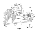
- the rear fastener 16 substantially identical to the half-fasteners 14a, 14b, comprises a double fitting 56 secured to a rear end of the spar 18 of the sub-wing box 12.
- This fitting 56 extends in a plane vertical oriented in the transverse direction Y, namely in a YZ plane, almost in the extension of a rear vertical partition 58 of the sub-wing box 12.
- the fitting 56 has a symmetry with respect to the vertical plane passing through the longitudinal axis 5 of the engine 2.
- This fitting 56 is pierced with two through holes 60 (only one being visible on the figure 3 ), oriented along the longitudinal direction X of the aircraft.
- Two triangular shackles 62 and 64 are respectively arranged on either side of this bracket 56, also in YZ planes.
- the front shackle 62 and the rear shackle 64 together form a pair of triangular shackles 66
- the shackles 62,64 are parallel to each other.
- the pair of triangular shackles 66 could here also be achieved using double shackles, without departing from the scope of the invention.
- the front shackle 62 is arranged so that it is one of its bases 62a which is mounted on the fitting 56, this base 62a being oriented substantially in the transverse direction Y In this way, it can then be understood that the shackle 62 is placed so that it extends vertically upwards along the Z direction from its base 62a to an opposite vertex 62b to this base 62a.
- a through-hole 68 is formed, oriented in the longitudinal direction X.
- the rear shackle 64 is arranged in a manner identical to that of the shackle before 62, namely that it is one of its bases 64a which is mounted on the fitting 56, and that this base 64a is oriented substantially in the transverse direction Y. Therefore, here too, it is practiced a through hole 70 oriented in the longitudinal direction X, close to each of the two vertices (not referenced) associated with this base 64a.
- the rear attachment 16 then has two lateral axes 72 and 74 oriented in the longitudinal direction X, and arranged in the same horizontal plane XY.
- the lateral axis 72 preferably double as shown in FIG. figure 3 , passes successively through one of the two through holes 68 of the front triangular shackle 62, one of the two through holes 60 made in the fitting 56, as well as one of the two through holes 70 of the rear triangular shackle 64.
- the lateral axis 74 preferably also double, successively passes through the other of the two through holes 68 of the front triangular shackle 62, the other of the two through holes 60 made in the fitting 56, and the other two through holes 70 of the rear triangular shackle 64.
- the rear attachment 16 is provided with another fitting 76 oriented generally in a vertical plane YZ and extending upwards by a horizontal plate 78, this plate 78 being integral with the horizontal intermediate spar of the wing 4. Consequently, the fitting 76 passes through a lower surface coating 22 of the wing 4.
- this bracket 76 is pierced with a single through hole 80, oriented along the longitudinal direction X of the aircraft.
- the front shackle 62 has a through hole 82 oriented in the longitudinal direction X, this hole 82 being formed near the top 62b opposite the aforementioned base 62a.
- the rear shackle 64 has a through hole 84 oriented in the longitudinal direction X, this hole 84 being formed near a vertex 64b opposite the base 64a indicated above.
- an upper axis 86 disposed above the lateral axes 72, 74 and preferably being double as shown in FIG. figure 3 , can then ensure the connection between the pair of shackles 66 and the fitting 76, successively passing through the through hole 82 of the front triangular shackle 62, the through hole 80 of the fitting 76, and the through hole 84 of the triangular shackle back 64.
- the longitudinal forces are transmitted by the front attachment 14.
- the transverse forces are transmitted by the rear attachment 16, while the forces in the vertical direction are simultaneously transmitted by the 14 and the rear attachment 16.
- the longitudinal forces pass directly through the ribs 44 and 54 of the wing structure 4, these ribs 44 and 54 being located generally towards the rear relative to the half-fasteners 14a, 14b.
- each half-fastener 14a, 14b is designed to take up and pass the forces according to the X and Z directions, and not in the Y direction.
- the rear attachment 16 is designed to take and pass the forces along the Y and Z directions, and not in the X direction.
- the moment along the longitudinal axis is taken up in the vertical direction by the two half-fasteners 14a, 14b of the front fastener 14, and the moment along the transverse axis is also taken up in the vertical direction by the assembly formed by the front and rear fasteners 14. Finally, the moment along the vertical axis is taken up in the longitudinal direction by the two half-fasteners 14a, 14b of the front fastener 14.
- an attachment device 100 is shown according to a second preferred embodiment of the present invention.
- This device 100 is substantially identical to the device 1 according to the first embodiment described above. Therefore, the elements bearing the same reference numerals correspond to identical or similar elements.
- the bases 30a and 32a of the two half-fasteners 14a, 14b of the front fastener 14 are connected to the fittings 44 and 54 of the wing 4, and the opposing vertices 30b and 32b are connected to the fittings 24 integral with the rigid structure 8.
- the bases 62a and 64a of the rear attachment 16 are connected to the fitting 76 integral with the flange 4, and the opposing apices 62b and 64b are connected to the fitting 56 integral with the rigid structure 8.
Landscapes
- Engineering & Computer Science (AREA)
- Aviation & Aerospace Engineering (AREA)
- Connection Of Plates (AREA)
- Vehicle Body Suspensions (AREA)
- Load-Engaging Elements For Cranes (AREA)
- Retarders (AREA)
- Ultra Sonic Daignosis Equipment (AREA)
- Catching Or Destruction (AREA)
Claims (10)
- Aufhängungsvorrichtung (1,100), die ein Triebwerk (2) mit einem Tragwerk (4) eines Luftfahrzeugs verbindet, wobei die Vorrichtung eine starre Struktur (8) sowie zwischen die starre Struktur (8) und das Tragwerk (4) eingefügte Aufhängungsmittel (10) aufweist, und die Aufhängungsmittel (10) ein vorderes Befestigungselement (14) sowie ein hinteres Befestigungselement (16), das mindestens einen dreieckigen Schäkel (62,64) aufweist, welcher in einer in einer Transversalrichtung (Y) des Luftfahrzeugs ausgerichteten Vertikalebene angeordnet ist, umfassen, wobei das vordere Befestigungselement (14) aus zwei Befestigungselementhälften (14a,14b) gebildet ist, welche jeweils auf der einen und der anderen Seite einer vertikalen, durch die Longitudinalachse (5) des Triebwerks (2) hindurchgehenden Ebene angeordnet sind,
dadurch gekennzeichnet, dass
jede Befestigungselementhälfte (14a,14b) mindestens einen dreieckigen Schäkel (30,32) aufweist, der in einer in einer Longitudinalrichtung (X) des Luftfahrzeugs ausgerichteten Vertikalebene angeordnet ist, und dass die Aufhängungsmittel (10) ausschließlich von dem vorderen Befestigungselement (14) und dem hinteren Befestigungselement (16) gebildet sind. - Aufhängungsvorrichtung (1,100) eines Triebwerks (2) nach Anspruch 1, dadurch gekennzeichnet, dass jede der zwei Befestigungselementhälften (14a,14b) so ausgestaltet ist, dass sie Kräfte aufnehmen kann, die in der Longitudinalrichtung (X) und der Vertikalrichtung (Z) des Luftfahrzeugs ausgeübt werden, und dass das hintere Befestigungselement (16) so ausgestaltet ist, dass es in der Transversalrichtung (Y) und der Vertikalrichtung (Z) ausgeübte Kräfte aufnehmen kann.
- Aufhängungsvorrichtung (1,100) eines Triebwerks (2) nach Anspruch 1 oder Anspruch 2, dadurch gekennzeichnet, dass das hintere Befestigungselement (16) ein Paar dreieckiger Schäkel (66) aufweist, die in Vertikalebenen angeordnet sind, die in der Transversalrichtung (Y) des Luftfahrzeugs ausgerichtet sind, und dass das vordere Befestigungselement (14) auf beiden Seiten der durch die Longitudinalachse (5) des Triebwerks (2) hindurchgehenden Vertikalebene ein Paar dreieckiger Schäkel (34) aufweist, welche in Vertikalebenen angeordnet sind, die in der Longitudinalrichtung (X) des Luftfahrzeugs ausgerichtet sind.
- Aufhängungsvorrichtung (1,100) eines Triebwerks (2) nach Anspruch 3, dadurch gekennzeichnet, dass das Paar dreieckiger Schäkel (66) des hinteren Befestigungselements (16) mit der starren Struktur (8) und dem Tragwerk (4) des Luftfahrzeugs über Achsen (72,74,86) verbunden ist, die in der Longitudinalrichtung (X) dieses Luftfahrzeugs ausgerichtet sind.
- Aufhängungsvorrichtung (1,100) eines Triebwerks (2) nach Anspruch 3 oder Anspruch 4, dadurch gekennzeichnet, dass jedes der zwei Paare dreieckiger Schäkel (34) des vorderen Befestigungselements (14) mit der starren Struktur (8) und dem Tragwerk (4) des Luftfahrzeugs über Achsen (40,42,52) verbunden ist, die in der Transversalrichtung (Y) des Luftfahrzeugs ausgerichtet sind.
- Aufhängungsvorrichtung (1,100) eines Triebwerks (2) nach einem der Ansprüche 3 bis 5, dadurch gekennzeichnet, dass das hintere Befestigungselement (16) außerdem ein mit der starren Struktur (8) fest verbundenes bzw. einstückiges Beschlagteil (56) aufweist, das mit dem Paar dreieckiger Schäkel (66) über mindestens eine, in der Longitudinalrichtung (X) dieses Luftfahrzeugs ausgerichtete Achse (70,72) verbunden ist, und dass das hintere Befestigungselement (16) ebenfalls ein mit dem Tragwerk (4) einstückiges bzw. fest verbundenes Beschlagteil (76) aufweist, das mit dem Paar dreieckiger Schäkel (66) über mindestens eine in der Longitudinalrichtung (X) dieses Luftfahrzeugs ausgerichtete Achse (86) verbunden ist.
- Aufhängungsvorrichtung (1,100) eines Triebwerks (2) nach einem der Ansprüche 3 bis 6, dadurch gekennzeichnet, dass das vordere Befestigungselement (14) außerdem zwei mit der starren Struktur (8) fest verbundene bzw. einstückige Beschlagteile (24) aufweist, und jedes Beschlagteil (24) mit einem der zwei Paare dreieckiger Schäkel (34) über mindestens eine in der Transversalrichtung (Y) dieses Luftfahrzeugs ausgerichtete Achse (40,42) verbunden ist, und dass das vordere Befestigungselement (14) auch zwei mit dem Tragwerk (4) fest verbundene bzw. einstückige Beschlagteile (44,54) aufweist, wobei jedes Beschlagteil (44,54) mit einem der zwei Paare dreieckiger Schäkel (34) mit mindestens einer in der Transversalrichtung (Y) dieses Luftfahrzeugs ausgerichteten Achse (52) verbunden ist.
- Aufhängungsvorrichtung (1,100) eines Triebwerks (2) nach einem der vorangehenden Ansprüche, dadurch gekennzeichnet, dass jeder dreieckige Schäkel (30,32,62,64) mit der starren Struktur (8) und dem Tragwerk (4) des Luftfahrzeugs mittels dreier Achsen (40,42,52,72,74,86) verbunden ist, die ihn jeweils in Nähe seiner drei Scheitel (30b,32b,62b,64b) durchsetzen.
- Aufhängungsvorrichtung (1) eines Triebwerks (2) nach einem der vorangehenden Ansprüche, dadurch gekennzeichnet, dass mindestens ein dreieckiger Schäkel (30,32,62,64) mit der starren Struktur (8) über eine seiner Basen (30a,32a,62a,64a) und mit dem Tragwerk (4) über den dieser Basis gegenüberliegenden Scheitel (30b,32b,62b,64b) verbunden ist.
- Aufhängungsvorrichtung (100) eines Triebwerks gemäß einem der Ansprüche 1 bis 8, dadurch gekennzeichnet, dass mindestens ein dreieckiger Schäkel (30,32,62,64) mit der starren Struktur (8) über einen seiner Scheitel (30b,32b,62b,64b) und mit dem Tragwerk (4) über die diesem Scheitel gegenüberliegende Basis (30a,32a,62a,64a) verbunden ist.
Applications Claiming Priority (2)
| Application Number | Priority Date | Filing Date | Title |
|---|---|---|---|
| FR0350906A FR2862610B1 (fr) | 2003-11-25 | 2003-11-25 | Dispositif d'accrochage reliant un moteur et une voilure d'aeronef |
| FR0350906 | 2003-11-25 |
Publications (2)
| Publication Number | Publication Date |
|---|---|
| EP1535837A1 EP1535837A1 (de) | 2005-06-01 |
| EP1535837B1 true EP1535837B1 (de) | 2008-07-16 |
Family
ID=34451745
Family Applications (1)
| Application Number | Title | Priority Date | Filing Date |
|---|---|---|---|
| EP04106018A Expired - Lifetime EP1535837B1 (de) | 2003-11-25 | 2004-11-23 | Vorrichtung für die Aufhängung eines Triebwerks an einem Flugzeugflügel |
Country Status (6)
| Country | Link |
|---|---|
| US (1) | US7121504B2 (de) |
| EP (1) | EP1535837B1 (de) |
| AT (1) | ATE401242T1 (de) |
| CA (1) | CA2486500C (de) |
| DE (1) | DE602004015048D1 (de) |
| FR (1) | FR2862610B1 (de) |
Families Citing this family (24)
| Publication number | Priority date | Publication date | Assignee | Title |
|---|---|---|---|---|
| FR2862611B1 (fr) * | 2003-11-25 | 2007-03-09 | Airbus France | Dispositif d'accrochage d'un moteur sous une voilure d'aeronef |
| FR2862944B1 (fr) * | 2003-12-01 | 2006-02-24 | Airbus France | Dispositif d'accrochage d'un turbopropulseur sous une voilure d'aeronef |
| FR2889163B1 (fr) * | 2005-07-29 | 2007-09-07 | Airbus France Sas | Ensemble pour aeronef comprenant un element de voilure ainsi qu'un mat d'accrochage |
| RU2304548C1 (ru) * | 2005-12-23 | 2007-08-20 | Закрытое акционерное общество "Гражданские самолеты Сухого" | Подвес двигателя к стреловидному крылу |
| FR2915178B1 (fr) * | 2007-04-23 | 2009-07-10 | Airbus France Sa | Attache d'un caisson de mat sur une voilure, pincant un panneau lateral du caisson |
| GB0722772D0 (en) * | 2007-11-21 | 2008-01-02 | Airbus Uk Ltd | Aircraft engine pylon attachment |
| US8342444B2 (en) * | 2008-12-16 | 2013-01-01 | The Boeing Company | Fail safe extended torque box strut-to-wing mount |
| FR2950860B1 (fr) * | 2009-10-01 | 2011-12-09 | Airbus Operations Sas | Dispositif d'accrochage d'un moteur a un mat d'aeronef |
| FR2958265B1 (fr) * | 2010-04-02 | 2012-03-23 | Airbus Operations Sas | Systeme d'axe pour ensemble de liaison d'un mat-reacteur sous une voilure d'aeronef |
| FR2958263B1 (fr) * | 2010-04-02 | 2012-03-23 | Airbus Operations Sas | Systeme d'axe pour ensemble de liaison d'un mat-reacteur sous une voilure d'aeronef |
| FR2958267B1 (fr) * | 2010-04-02 | 2012-03-23 | Airbus Operations Sas | Systeme d'axe pour ensemble de liaison d'un mat-reacteur sous une voilure d'aeronef |
| FR2958262B1 (fr) * | 2010-04-02 | 2012-03-23 | Airbus Operations Sas | Systeme d'axe pour ensemble de liaison d'un mat-reacteur sous une voilure d'aeronef |
| FR2958264B1 (fr) * | 2010-04-02 | 2012-03-23 | Airbus Operations Sas | Systeme d'axe pour ensemble de liaison d'un mat-reacteur sous une voilure d'aeronef |
| FR2958266B1 (fr) * | 2010-04-02 | 2012-03-23 | Airbus Operations Sas | Systeme d'axe pour ensemble de liaison d'un mat-reacteur sous une voilure d'aeronef |
| JP6266775B2 (ja) | 2013-07-26 | 2018-01-24 | エムアールエイ・システムズ・エルエルシー | 航空機エンジンパイロン |
| EP3071481B1 (de) | 2013-11-18 | 2020-01-08 | LORD Corporation | Befestigungssysteme und verfahren für turboprop-triebwerk |
| US9238511B2 (en) | 2014-03-04 | 2016-01-19 | Mra Systems, Inc. | Engine pylon structure |
| FR3065441B1 (fr) * | 2017-04-19 | 2019-07-05 | Airbus Operations | Ensemble pour aeronef comprenant une structure primaire de mat d'accrochage fixee a un caisson de voilure a l'aide d'une liaison boulonnee |
| FR3080096B1 (fr) * | 2018-04-11 | 2020-03-13 | Airbus Operations | Attache-moteur d'aeronef comprenant des elements de fixation inclines, aeronef comprenant ladite attache-moteur et procede de fixation d'un moteur a un mat d'aeronef utilisant ladite attache-moteur |
| FR3098193B1 (fr) * | 2019-07-03 | 2022-02-11 | Airbus Operations Sas | Aéronef comprenant une attache voilure arrière présentant au moins un pion solidaire d’une structure primaire d’un mât |
| GB2586476A (en) | 2019-08-20 | 2021-02-24 | Airbus Operations Ltd | Aircraft wing-pylon connection |
| FR3120603A1 (fr) * | 2021-03-11 | 2022-09-16 | Airbus Operations (S.A.S.) | Mât d’aéronef comprenant une structure primaire tubulaire intégrant au moins une canalisation à double peau et aéronef comportant au moins un tel mât |
| US12415610B2 (en) * | 2022-05-13 | 2025-09-16 | The Boeing Company | Strut assembly and method for coupling an engine to a wing of an aircraft |
| EP4729415A1 (de) | 2024-10-16 | 2026-04-22 | Airbus Operations (S.A.S.) | Flugzeug mit mindestens einem tragflächenbefestigungssystem zur optimalen übertragung von schubkräften |
Family Cites Families (3)
| Publication number | Priority date | Publication date | Assignee | Title |
|---|---|---|---|---|
| US3042349A (en) * | 1959-11-13 | 1962-07-03 | Gen Electric | Removable aircraft engine mounting arrangement |
| FR2738034B1 (fr) | 1995-08-23 | 1997-09-19 | Snecma | Dispositif de suspension d'un turbopropulseur |
| FR2836672B1 (fr) * | 2002-03-04 | 2004-06-04 | Airbus France | Mat d'accrochage d'un moteur sous une voilure d'aeronef |
-
2003
- 2003-11-25 FR FR0350906A patent/FR2862610B1/fr not_active Expired - Fee Related
-
2004
- 2004-11-23 CA CA2486500A patent/CA2486500C/fr not_active Expired - Fee Related
- 2004-11-23 AT AT04106018T patent/ATE401242T1/de not_active IP Right Cessation
- 2004-11-23 US US10/994,483 patent/US7121504B2/en not_active Expired - Lifetime
- 2004-11-23 EP EP04106018A patent/EP1535837B1/de not_active Expired - Lifetime
- 2004-11-23 DE DE602004015048T patent/DE602004015048D1/de not_active Expired - Lifetime
Also Published As
| Publication number | Publication date |
|---|---|
| EP1535837A1 (de) | 2005-06-01 |
| CA2486500C (fr) | 2013-01-08 |
| US7121504B2 (en) | 2006-10-17 |
| ATE401242T1 (de) | 2008-08-15 |
| CA2486500A1 (fr) | 2005-05-25 |
| FR2862610B1 (fr) | 2007-03-23 |
| US20050151008A1 (en) | 2005-07-14 |
| FR2862610A1 (fr) | 2005-05-27 |
| DE602004015048D1 (de) | 2008-08-28 |
Similar Documents
| Publication | Publication Date | Title |
|---|---|---|
| EP1535838B1 (de) | Aufhängung eines Triebwerks unter einer Flugzeugtragfläche | |
| EP1535837B1 (de) | Vorrichtung für die Aufhängung eines Triebwerks an einem Flugzeugflügel | |
| EP1535839B1 (de) | Aufhängevorrichtung eines Triebweks unter einem Fluzeugflügel | |
| EP1910167B1 (de) | Anordnung für ein flugzeug mit einem flügelsystemelement und einem befestigungsmast | |
| EP1480876B1 (de) | Aufhängung eines triebwerks unter einer flugzeugtragfläche | |
| EP2137072B1 (de) | Vorrichtung zur befestigung eines flugzeugtriebwerks und flugzeug mit mindestens einer derartigen vorrichtung | |
| EP1538081B1 (de) | Aufhängung eines Triebwerks unter einer Flugzeugflügel | |
| FR2917713A1 (fr) | Dispositif d'accrochage de moteur d'aeronef et aeronef comportant au moins un tel dispositif. | |
| FR2903666A1 (fr) | Ensemble moteur pour aeronef comprenant un capotage aerodynamique de jonction monte sur deux elements distincts | |
| FR2903383A1 (fr) | Dispositif d'accrochage d'un moteur d'aeronef comportant deux bielles de reprise de poussee a double liaison mecanique arriere | |
| EP3505448B1 (de) | Einheit für ein luftfahrzeug, die eine primärstruktur eines aufhängungsmasts umfasst, die an einem flügelkasten mithilfe von anschlüssen reduzierten volumens in der vorderkantenzone befestigt ist | |
| EP1773660B1 (de) | Flugzeugmotoreinheit | |
| FR2964364A1 (fr) | Mat d'accrochage de turboreacteur pour aeronef comprenant des attaches voilure avant alignees | |
| FR2891244A1 (fr) | Mat d'accrochage de moteur pour aeronef | |
| FR2916736A1 (fr) | Dispositif d'accrochage d'un turbopropulseur d'aeronef comprenant des moyens de fixation hydrauliques. | |
| FR2891251A1 (fr) | Mat d'accrochage de moteur pour aeronef | |
| EP1773659B1 (de) | Flugzeugmotoranordnung | |
| FR3065442A1 (fr) | Ensemble moteur pour aeronef comprenant une attache moteur avant integree au caisson du mat d'accrochage | |
| FR2891247A1 (fr) | Ensemble pour aeronef comprenant un element de voilure ainsi qu'un mat d'accrochage | |
| FR2905932A1 (fr) | Agencement pour attache de dispositif d'accrochage d'un moteur d'aeronef | |
| EP3437999A1 (de) | Leichte primärstruktur für aufhängemast eines triebwerks eines luftfahrzeugs | |
| FR2887522A1 (fr) | Ensemble pour aeronef comprenant un element de voilure ainsi qu'un mat d'accrochage |
Legal Events
| Date | Code | Title | Description |
|---|---|---|---|
| PUAI | Public reference made under article 153(3) epc to a published international application that has entered the european phase |
Free format text: ORIGINAL CODE: 0009012 |
|
| AK | Designated contracting states |
Kind code of ref document: A1 Designated state(s): AT BE BG CH CY CZ DE DK EE ES FI FR GB GR HU IE IS IT LI LU MC NL PL PT RO SE SI SK TR |
|
| AX | Request for extension of the european patent |
Extension state: AL HR LT LV MK YU |
|
| RIN1 | Information on inventor provided before grant (corrected) |
Inventor name: MACHADO, STEPHANE Inventor name: DEL BLANCO, ANTHONY Inventor name: MARTIN, YVON Inventor name: CASSAGNE, JEROEME Inventor name: CHAMBREUIL, ARNAUD |
|
| 17P | Request for examination filed |
Effective date: 20050715 |
|
| AKX | Designation fees paid |
Designated state(s): AT BE BG CH CY CZ DE DK EE ES FI FR GB GR HU IE IS IT LI LU MC NL PL PT RO SE SI SK TR |
|
| GRAP | Despatch of communication of intention to grant a patent |
Free format text: ORIGINAL CODE: EPIDOSNIGR1 |
|
| RIN1 | Information on inventor provided before grant (corrected) |
Inventor name: DEL BLANCO, ANTHONY Inventor name: MACHADO, STEPHANE Inventor name: CASSAGNE, JEROME Inventor name: CHAMBREUIL, ARNAUD Inventor name: MARTIN, YVON |
|
| RTI1 | Title (correction) |
Free format text: ENGINE SUSPENSION ATTACHMENT DEVICE OF AN ENGINE TO AN AIRCRAFT WING |
|
| GRAS | Grant fee paid |
Free format text: ORIGINAL CODE: EPIDOSNIGR3 |
|
| GRAA | (expected) grant |
Free format text: ORIGINAL CODE: 0009210 |
|
| AK | Designated contracting states |
Kind code of ref document: B1 Designated state(s): AT BE BG CH CY CZ DE DK EE ES FI FR GB GR HU IE IS IT LI LU MC NL PL PT RO SE SI SK TR |
|
| REG | Reference to a national code |
Ref country code: GB Ref legal event code: FG4D Free format text: NOT ENGLISH |
|
| REG | Reference to a national code |
Ref country code: CH Ref legal event code: EP |
|
| REF | Corresponds to: |
Ref document number: 602004015048 Country of ref document: DE Date of ref document: 20080828 Kind code of ref document: P |
|
| REG | Reference to a national code |
Ref country code: IE Ref legal event code: FG4D Free format text: LANGUAGE OF EP DOCUMENT: FRENCH |
|
| REG | Reference to a national code |
Ref country code: SE Ref legal event code: TRGR |
|
| NLV1 | Nl: lapsed or annulled due to failure to fulfill the requirements of art. 29p and 29m of the patents act | ||
| PG25 | Lapsed in a contracting state [announced via postgrant information from national office to epo] |
Ref country code: ES Free format text: LAPSE BECAUSE OF FAILURE TO SUBMIT A TRANSLATION OF THE DESCRIPTION OR TO PAY THE FEE WITHIN THE PRESCRIBED TIME-LIMIT Effective date: 20081027 Ref country code: PT Free format text: LAPSE BECAUSE OF FAILURE TO SUBMIT A TRANSLATION OF THE DESCRIPTION OR TO PAY THE FEE WITHIN THE PRESCRIBED TIME-LIMIT Effective date: 20081216 Ref country code: IS Free format text: LAPSE BECAUSE OF FAILURE TO SUBMIT A TRANSLATION OF THE DESCRIPTION OR TO PAY THE FEE WITHIN THE PRESCRIBED TIME-LIMIT Effective date: 20081116 Ref country code: NL Free format text: LAPSE BECAUSE OF FAILURE TO SUBMIT A TRANSLATION OF THE DESCRIPTION OR TO PAY THE FEE WITHIN THE PRESCRIBED TIME-LIMIT Effective date: 20080716 |
|
| PG25 | Lapsed in a contracting state [announced via postgrant information from national office to epo] |
Ref country code: SI Free format text: LAPSE BECAUSE OF FAILURE TO SUBMIT A TRANSLATION OF THE DESCRIPTION OR TO PAY THE FEE WITHIN THE PRESCRIBED TIME-LIMIT Effective date: 20080716 Ref country code: FI Free format text: LAPSE BECAUSE OF FAILURE TO SUBMIT A TRANSLATION OF THE DESCRIPTION OR TO PAY THE FEE WITHIN THE PRESCRIBED TIME-LIMIT Effective date: 20080716 Ref country code: AT Free format text: LAPSE BECAUSE OF FAILURE TO SUBMIT A TRANSLATION OF THE DESCRIPTION OR TO PAY THE FEE WITHIN THE PRESCRIBED TIME-LIMIT Effective date: 20080716 Ref country code: BG Free format text: LAPSE BECAUSE OF FAILURE TO SUBMIT A TRANSLATION OF THE DESCRIPTION OR TO PAY THE FEE WITHIN THE PRESCRIBED TIME-LIMIT Effective date: 20081016 |
|
| REG | Reference to a national code |
Ref country code: IE Ref legal event code: FD4D |
|
| PG25 | Lapsed in a contracting state [announced via postgrant information from national office to epo] |
Ref country code: DK Free format text: LAPSE BECAUSE OF FAILURE TO SUBMIT A TRANSLATION OF THE DESCRIPTION OR TO PAY THE FEE WITHIN THE PRESCRIBED TIME-LIMIT Effective date: 20080716 Ref country code: EE Free format text: LAPSE BECAUSE OF FAILURE TO SUBMIT A TRANSLATION OF THE DESCRIPTION OR TO PAY THE FEE WITHIN THE PRESCRIBED TIME-LIMIT Effective date: 20080716 Ref country code: IE Free format text: LAPSE BECAUSE OF FAILURE TO SUBMIT A TRANSLATION OF THE DESCRIPTION OR TO PAY THE FEE WITHIN THE PRESCRIBED TIME-LIMIT Effective date: 20080716 |
|
| PLBE | No opposition filed within time limit |
Free format text: ORIGINAL CODE: 0009261 |
|
| STAA | Information on the status of an ep patent application or granted ep patent |
Free format text: STATUS: NO OPPOSITION FILED WITHIN TIME LIMIT |
|
| PG25 | Lapsed in a contracting state [announced via postgrant information from national office to epo] |
Ref country code: RO Free format text: LAPSE BECAUSE OF FAILURE TO SUBMIT A TRANSLATION OF THE DESCRIPTION OR TO PAY THE FEE WITHIN THE PRESCRIBED TIME-LIMIT Effective date: 20080716 Ref country code: CZ Free format text: LAPSE BECAUSE OF FAILURE TO SUBMIT A TRANSLATION OF THE DESCRIPTION OR TO PAY THE FEE WITHIN THE PRESCRIBED TIME-LIMIT Effective date: 20080716 Ref country code: SK Free format text: LAPSE BECAUSE OF FAILURE TO SUBMIT A TRANSLATION OF THE DESCRIPTION OR TO PAY THE FEE WITHIN THE PRESCRIBED TIME-LIMIT Effective date: 20080716 |
|
| BERE | Be: lapsed |
Owner name: AIRBUS FRANCE Effective date: 20081130 |
|
| 26N | No opposition filed |
Effective date: 20090417 |
|
| PG25 | Lapsed in a contracting state [announced via postgrant information from national office to epo] |
Ref country code: MC Free format text: LAPSE BECAUSE OF NON-PAYMENT OF DUE FEES Effective date: 20081130 |
|
| REG | Reference to a national code |
Ref country code: CH Ref legal event code: PL |
|
| PG25 | Lapsed in a contracting state [announced via postgrant information from national office to epo] |
Ref country code: BE Free format text: LAPSE BECAUSE OF NON-PAYMENT OF DUE FEES Effective date: 20081130 |
|
| PG25 | Lapsed in a contracting state [announced via postgrant information from national office to epo] |
Ref country code: LI Free format text: LAPSE BECAUSE OF NON-PAYMENT OF DUE FEES Effective date: 20081130 Ref country code: CH Free format text: LAPSE BECAUSE OF NON-PAYMENT OF DUE FEES Effective date: 20081130 |
|
| PG25 | Lapsed in a contracting state [announced via postgrant information from national office to epo] |
Ref country code: PL Free format text: LAPSE BECAUSE OF FAILURE TO SUBMIT A TRANSLATION OF THE DESCRIPTION OR TO PAY THE FEE WITHIN THE PRESCRIBED TIME-LIMIT Effective date: 20080716 |
|
| PG25 | Lapsed in a contracting state [announced via postgrant information from national office to epo] |
Ref country code: CY Free format text: LAPSE BECAUSE OF FAILURE TO SUBMIT A TRANSLATION OF THE DESCRIPTION OR TO PAY THE FEE WITHIN THE PRESCRIBED TIME-LIMIT Effective date: 20080716 Ref country code: HU Free format text: LAPSE BECAUSE OF FAILURE TO SUBMIT A TRANSLATION OF THE DESCRIPTION OR TO PAY THE FEE WITHIN THE PRESCRIBED TIME-LIMIT Effective date: 20090117 Ref country code: LU Free format text: LAPSE BECAUSE OF NON-PAYMENT OF DUE FEES Effective date: 20081123 |
|
| PG25 | Lapsed in a contracting state [announced via postgrant information from national office to epo] |
Ref country code: TR Free format text: LAPSE BECAUSE OF FAILURE TO SUBMIT A TRANSLATION OF THE DESCRIPTION OR TO PAY THE FEE WITHIN THE PRESCRIBED TIME-LIMIT Effective date: 20080716 |
|
| PG25 | Lapsed in a contracting state [announced via postgrant information from national office to epo] |
Ref country code: GR Free format text: LAPSE BECAUSE OF FAILURE TO SUBMIT A TRANSLATION OF THE DESCRIPTION OR TO PAY THE FEE WITHIN THE PRESCRIBED TIME-LIMIT Effective date: 20081017 |
|
| REG | Reference to a national code |
Ref country code: GB Ref legal event code: 732E Free format text: REGISTERED BETWEEN 20110721 AND 20110727 |
|
| REG | Reference to a national code |
Ref country code: FR Ref legal event code: CD Owner name: AIRBUS HOLDING, FR Effective date: 20110916 Ref country code: FR Ref legal event code: CA Effective date: 20110916 Ref country code: FR Ref legal event code: TP Owner name: AIRBUS HOLDING, FR Effective date: 20110913 Ref country code: FR Ref legal event code: CJ Effective date: 20110916 |
|
| REG | Reference to a national code |
Ref country code: DE Ref legal event code: R082 Ref document number: 602004015048 Country of ref document: DE Representative=s name: HENKEL, BREUER & PARTNER, DE |
|
| REG | Reference to a national code |
Ref country code: DE Ref legal event code: R081 Ref document number: 602004015048 Country of ref document: DE Owner name: AIRBUS OPERATIONS SAS, FR Free format text: FORMER OWNER: AIRBUS FRANCE, TOULOUSE, FR Effective date: 20120326 Ref country code: DE Ref legal event code: R082 Ref document number: 602004015048 Country of ref document: DE Representative=s name: PATENTANWAELTE HENKEL, BREUER & PARTNER, DE Effective date: 20120326 |
|
| PGFP | Annual fee paid to national office [announced via postgrant information from national office to epo] |
Ref country code: SE Payment date: 20121120 Year of fee payment: 9 |
|
| REG | Reference to a national code |
Ref country code: SE Ref legal event code: EUG |
|
| PG25 | Lapsed in a contracting state [announced via postgrant information from national office to epo] |
Ref country code: SE Free format text: LAPSE BECAUSE OF NON-PAYMENT OF DUE FEES Effective date: 20131124 |
|
| REG | Reference to a national code |
Ref country code: FR Ref legal event code: PLFP Year of fee payment: 12 |
|
| REG | Reference to a national code |
Ref country code: FR Ref legal event code: PLFP Year of fee payment: 13 |
|
| REG | Reference to a national code |
Ref country code: FR Ref legal event code: PLFP Year of fee payment: 14 |
|
| PGFP | Annual fee paid to national office [announced via postgrant information from national office to epo] |
Ref country code: DE Payment date: 20191121 Year of fee payment: 16 |
|
| PGFP | Annual fee paid to national office [announced via postgrant information from national office to epo] |
Ref country code: IT Payment date: 20191128 Year of fee payment: 16 |
|
| PGFP | Annual fee paid to national office [announced via postgrant information from national office to epo] |
Ref country code: GB Payment date: 20191120 Year of fee payment: 16 |
|
| REG | Reference to a national code |
Ref country code: DE Ref legal event code: R119 Ref document number: 602004015048 Country of ref document: DE |
|
| GBPC | Gb: european patent ceased through non-payment of renewal fee |
Effective date: 20201123 |
|
| PG25 | Lapsed in a contracting state [announced via postgrant information from national office to epo] |
Ref country code: IT Free format text: LAPSE BECAUSE OF NON-PAYMENT OF DUE FEES Effective date: 20201123 |
|
| PG25 | Lapsed in a contracting state [announced via postgrant information from national office to epo] |
Ref country code: DE Free format text: LAPSE BECAUSE OF NON-PAYMENT OF DUE FEES Effective date: 20210601 Ref country code: GB Free format text: LAPSE BECAUSE OF NON-PAYMENT OF DUE FEES Effective date: 20201123 |
|
| PGFP | Annual fee paid to national office [announced via postgrant information from national office to epo] |
Ref country code: FR Payment date: 20231120 Year of fee payment: 20 |