EP1535837B1 - Engine suspension attachment device of an engine to an aircraft wing - Google Patents
Engine suspension attachment device of an engine to an aircraft wing Download PDFInfo
- Publication number
- EP1535837B1 EP1535837B1 EP04106018A EP04106018A EP1535837B1 EP 1535837 B1 EP1535837 B1 EP 1535837B1 EP 04106018 A EP04106018 A EP 04106018A EP 04106018 A EP04106018 A EP 04106018A EP 1535837 B1 EP1535837 B1 EP 1535837B1
- Authority
- EP
- European Patent Office
- Prior art keywords
- aircraft
- wing
- engine
- attachment
- triangular
- Prior art date
- Legal status (The legal status is an assumption and is not a legal conclusion. Google has not performed a legal analysis and makes no representation as to the accuracy of the status listed.)
- Active
Links
- 239000000725 suspension Substances 0.000 title description 4
- 230000008878 coupling Effects 0.000 abstract description 7
- 238000010168 coupling process Methods 0.000 abstract description 7
- 238000005859 coupling reaction Methods 0.000 abstract description 7
- 230000005540 biological transmission Effects 0.000 description 2
- 230000003068 static effect Effects 0.000 description 2
- 230000008859 change Effects 0.000 description 1
- 239000011248 coating agent Substances 0.000 description 1
- 238000000576 coating method Methods 0.000 description 1
- 239000000470 constituent Substances 0.000 description 1
- 238000012217 deletion Methods 0.000 description 1
- 230000037430 deletion Effects 0.000 description 1
- 238000012423 maintenance Methods 0.000 description 1
- 238000012986 modification Methods 0.000 description 1
- 230000004048 modification Effects 0.000 description 1
- 238000005192 partition Methods 0.000 description 1
- 239000003380 propellant Substances 0.000 description 1
- 230000009467 reduction Effects 0.000 description 1
- 238000005204 segregation Methods 0.000 description 1
Images


Classifications
-
- B—PERFORMING OPERATIONS; TRANSPORTING
- B64—AIRCRAFT; AVIATION; COSMONAUTICS
- B64D—EQUIPMENT FOR FITTING IN OR TO AIRCRAFT; FLIGHT SUITS; PARACHUTES; ARRANGEMENTS OR MOUNTING OF POWER PLANTS OR PROPULSION TRANSMISSIONS IN AIRCRAFT
- B64D27/00—Arrangement or mounting of power plant in aircraft; Aircraft characterised thereby
- B64D27/02—Aircraft characterised by the type or position of power plant
- B64D27/10—Aircraft characterised by the type or position of power plant of gas-turbine type
- B64D27/12—Aircraft characterised by the type or position of power plant of gas-turbine type within or attached to wing
-
- B64D27/40—
Abstract
Description
La présente invention se rapporte à un dispositif apte à assurer la liaison entre un moteur et une voilure d'aéronef, ce dispositif comprenant une structure rigide et des moyens d'accrochage interposés entre cette structure rigide et la voilure. En particulier, l'invention se rapporte à un dispositif apte à assurer la suspension d'un moteur sous une voilure d'aéronef, ce dispositif comprenant une structure rigide et des moyens d'accrochage de cette structure rigide sous la voilure.The present invention relates to a device adapted to provide the connection between a motor and an aircraft wing, this device comprising a rigid structure and attachment means interposed between this rigid structure and the wing. In particular, the invention relates to a device adapted to ensure the suspension of an engine under an aircraft wing, this device comprising a rigid structure and means for hooking this rigid structure under the wing.
Un tel dispositif peut être utilisé sur tout type d'aéronef comportant des moteurs suspendus à sa voilure ou montés au-dessus de celle-ci, tels que des turboréacteurs ou des turbopropulseurs.Such a device can be used on any type of aircraft comprising engines suspended at its wing or mounted above it, such as turbojets or turboprops.
Sur les aéronefs existants, les moteurs sont suspendus en dessous de la voilure par des dispositifs d'accrochage complexes, également appelés « EMS » (de l'anglais « Engine Mounting Structure »). Dans le cas des turboréacteurs, les dispositifs d'accrochage habituellement employés présentent une structure rigide du type caisson, également appelée « mât », c'est-à-dire formée par l'assemblage de longerons inférieurs et supérieurs raccordés entre-eux par une pluralité de nervures transversales. D'autre part, les dispositifs d'accrochage de turbopropulseurs sont quant à eux généralement constitués d'un caisson sous-aile arrière, prolongé par une structure en treillis, vers l'avant dans la direction longitudinale du turbopropulseur.On existing aircraft, engines are suspended below the wing by complex attachment devices, also called "EMS" (the English "Engine Mounting Structure"). In the case of turbojets, the attachment devices usually employed have a rigid structure of the box type, also called "mast", that is to say formed by the assembly of lower and upper beams connected together. by a plurality of transverse ribs. On the other hand, the turboprop coupling devices are generally consist of a sub-wing box rear, extended by a lattice structure, forwards in the longitudinal direction of the turboprop.
De façon connue, ces dispositifs sont notamment conçus pour permettre la transmission à la voilure des efforts statiques et dynamiques engendrés par les moteurs, tels que le poids, la poussée, ou encore les différents efforts dynamiques.In known manner, these devices are especially designed to allow the transmission to the wing of the static and dynamic forces generated by the engines, such as weight, thrust, or the different dynamic forces.
A ce titre, dans les dispositifs d'accrochage connus de l'art antérieur,comme dans le document
Pour ce faire, l'attache avant comprend deux groupes de manilles respectivement placés verticalement de chaque côté de la structure rigide. Chaque groupe de manilles relie une ferrure à double tête solidaire des longerons supérieurs de la structure rigide du dispositif, à une ferrure à double tête solidaire d'un longeron avant de la voilure. Les liaisons entre les groupes de manilles et les ferrures sont assurées par des axes orientés selon une direction transversale par rapport à l'aéronef, c'est-à-dire selon une direction orthogonale à la fois à la verticale et à l'axe longitudinal de cet aéronef.To do this, the front attachment comprises two groups of shackles respectively placed vertically on each side of the rigid structure. Each group of shackles connects a double-head fitting secured to the upper longitudinal members of the rigid structure of the device, to a dual-head fitting integral with a front spar of the wing. The links between the groups of shackles and the fittings are provided by axes oriented in a direction transverse to the aircraft, that is to say in a direction orthogonal to both the vertical and the longitudinal axis of this aircraft.
L'attache arrière comporte deux paires de manilles triangulaires placées dans des plans verticaux orientés selon la direction transversale de l'aéronef. Ces deux paires de manilles triangulaires relient une ferrure double solidaire du longeron supérieur arrière de la structure rigide, à une ferrure solidaire d'un longeron intermédiaire de la voilure. Les liaisons entre les deux paires de manilles et les ferrures sont alors ici assurées par des axes orientés selon la direction longitudinale de l'aéronef.The rear attachment has two pairs of triangular shackles placed in vertical planes oriented in the transverse direction of the aircraft. These two pairs of triangular shackles connect a double fitting integral with the rear upper spar of the rigid structure, to a bracket integral with an intermediate spar of the wing. The links between the two pairs of shackles and the fittings are here ensured by axes oriented along the longitudinal direction of the aircraft.
L'attache intermédiaire destinée à reprendre les efforts de poussée, également appelée attache « spigot », est de façon générale matérialisée par une rotule d'axe vertical fixée dans le longeron supérieur arrière de la structure rigide, entre l'attache avant et l'attache arrière. Cette attache spigot est un pion de cisaillement fixé sous la voilure de l'aéronef, de façon à faire saillie verticalement dans la rotule susmentionnée.The intermediate fastener intended to take up the thrust forces, also known as the "spigot" fastener, is generally embodied by a ball of vertical axis fixed in the rear upper spar of the rigid structure, between the front fastener and the rear attachment. This spigot attachment is a shear pin fixed under the wing of the aircraft, so as to protrude vertically in the aforementioned ball joint.
Dans cet agencement classique et isostatique de l'art antérieur, les efforts longitudinaux (poussée, inverseurs) sont transmis par l'attache intermédiaire. Les efforts transversaux se répartissent entre cette même attache intermédiaire et l'attache arrière, tandis que les efforts selon la direction verticale passent simultanément par l'attache avant et l'attache arrière.In this conventional and isostatic arrangement of the prior art, the longitudinal forces (thrust, reversers) are transmitted by the intermediate fastener. The transverse forces are distributed between the same intermediate attachment and the rear attachment, while the efforts in the vertical direction pass simultaneously through the front attachment and the rear attachment.
Par ailleurs, le moment selon l'axe longitudinal est repris par l'attache avant, et le moment selon l'axe transversal est repris dans la direction verticale par l'ensemble formé par les attaches avant et arrière. Enfin, le moment selon l'axe vertical est repris dans la direction transversale par l'ensemble formé par l'attache intermédiaire et l'attache arrière.Furthermore, the moment along the longitudinal axis is taken up by the front attachment, and the moment along the transverse axis is taken up in the vertical direction by the assembly formed by the front and rear fasteners. Finally, the moment along the vertical axis is taken in the transverse direction by the assembly formed by the intermediate attachment and the rear attachment.
Si la solution qui vient d'être présentée permet de transmettre de façon satisfaisante les efforts statiques et dynamiques engendrés par le moteur dans toutes les conditions de vol, elle présente néanmoins des inconvénients non-négligeables.If the solution that has just been presented makes it possible to satisfactorily transmit the static and dynamic forces generated by the engine in all flight conditions, it nevertheless has non-negligible disadvantages.
Effectivement, il est indiqué que dans la mesure où la fonction principale de l'attache intermédiaire est de reprendre les efforts de poussée, celle-ci présente ainsi nécessairement un encombrement important ainsi qu'une masse relativement élevée. Naturellement, cela conduit inévitablement à une augmentation sensible de la masse globale du dispositif d'accrochage.Indeed, it is indicated that insofar as the main function of the intermediate fastener is to resume thrust forces, it necessarily has a large footprint and a relatively high mass. Naturally, this inevitably leads to a significant increase in the overall mass of the attachment device.
D'autre part, il est noté que la plaque de fixation solidaire du pion de cisaillement, requise pour assurer l'assemblage de ce dernier sous la voilure de l'aéronef, est une pièce de conception complexe et difficile à définir. Ceci s'explique bien évidemment en raison de la nécessité de faire coopérer cette plaque de fixation avec les éléments constitutifs de la structure de la voilure, c'est-à-dire principalement des longerons et des nervures.On the other hand, it is noted that the fastening plate integral with the shear pin, required to ensure the assembly of the latter under the wing of the aircraft, is a piece of complex design and difficult to define. This is obviously due to the need to cooperate this fixing plate with the components of the structure of the wing, that is to say, mainly longitudinal members and ribs.
L'invention a donc pour but de proposer un dispositif d'accrochage reliant un moteur et une voilure d'aéronef, ce dispositif remédiant au moins partiellement aux inconvénients mentionnés ci-dessus relatifs aux réalisations de l'art antérieur.The invention therefore aims to provide a coupling device connecting a motor and an aircraft wing, this device at least partially overcomes the disadvantages mentioned above relating to the embodiments of the prior art.
Plus précisément, le but de l'invention est de présenter un dispositif d'accrochage reliant un moteur et une voilure d'aéronef, comprenant notamment des moyens d'accrochage interposés entre cette structure rigide et la voilure, et dont la conception de ces moyens est sensiblement simplifiée par rapport à celle rencontrée antérieurement.More specifically, the object of the invention is to present a hooking device connecting a motor and an aircraft wing, comprising in particular attachment means interposed between this rigid structure and the wing, and the design of these means. is significantly simplified compared to that previously encountered.
Pour ce faire, l'invention a pour objet un dispositif d'accrochage reliant un moteur et une voilure d'aéronef, le dispositif comportant une structure rigide et des moyens d'accrochage interposés entre cette structure rigide et la voilure, les moyens d'accrochage comportant une attache avant ainsi qu'une attache arrière comprenant au moins une manille triangulaire placée dans un plan vertical orienté selon une direction transversale de l'aéronef, cette attache avant étant constituée de deux demi-attaches disposées respectivement de part et d'autre d'un plan vertical passant par un axe longitudinal du moteur. Selon l'invention, chaque demi-attache comprend au moins une manille triangulaire placée dans un plan vertical orienté selon une direction longitudinale de cet aéronef et les moyens d'accrochage sont exclusivement constitués par les attaches avant et arrière susmentionnées.To do this, the invention relates to a coupling device connecting a motor and an aircraft wing, the device comprising a rigid structure and attachment means interposed between this rigid structure and the wing, the means of fastening comprising a front attachment and a rear attachment comprising at least one triangular shackle placed in a vertical plane oriented in a transverse direction of the aircraft, this front attachment consisting of two half-fasteners respectively arranged on either side a vertical plane passing through a longitudinal axis of the engine. According to the invention, each half-attachment comprises at least one triangular shackle placed in a vertical plane oriented in a longitudinal direction of this aircraft and the attachment means are exclusively constituted by the aforementioned front and rear fasteners.
Avantageusement, la conception des moyens d'accrochage du dispositif selon l'invention est largement simplifiée par rapport à celle rencontrée dans les dispositifs d'accrochage de l'art antérieur, principalement en raison du fait qu'il n'est plus requis d'attache intermédiaire du type attache spigot.Advantageously, the design of the attachment means of the device according to the invention is largely simplified with respect to that encountered in the attachment devices of the prior art, mainly due to the fact that it is no longer required to intermediate attachment of the spigot attachment type.
Effectivement, dans cet agencement isostatique de la présente invention, les efforts longitudinaux sont transmis par chacune des demi-attaches de l'attache avant, les efforts transversaux sont transmis par l'attache arrière, et les efforts selon la direction verticale passent simultanément par les deux demi-attaches avant et l'attache arrière comprenant chacune au moins une manille triangulaire.Indeed, in this isostatic arrangement of the present invention, the longitudinal forces are transmitted by each of the half-fasteners of the front attachment, the transverse forces are transmitted by the rear attachment, and the forces in the vertical direction simultaneously pass through the two front half-fasteners and the rear attachment each comprising at least one triangular shackle.
Ainsi, la suppression de cette attache intermédiaire du type spigot engendre inéluctablement une diminution considérable de la masse et de l'encombrement relatifs aux moyens d'accrochage, et par conséquent une baisse non-négligeable de la masse globale et du coût du dispositif d'accrochage.Thus, the deletion of this spigot-type intermediate fastener inevitably leads to a considerable reduction in the mass and bulk relative to the fastening means, and consequently to a non-negligible decrease in the overall mass and the cost of the device. hanging.
De préférence, l'attache arrière comporte une paire de manilles triangulaires placées dans des plans verticaux orientés selon la direction transversale de l'aéronef, et l'attache avant comprend, de part et d'autre du plan vertical passant par l'axe longitudinal du moteur, une paire de manilles triangulaires placées dans des plans verticaux orientés selon la direction longitudinale de l'aéronef. Bien entendu, le fait de prévoir des paires de manilles permet d'obtenir des caractéristiques de résistance mécanique supérieures à celles obtenues avec des solutions mettant en oeuvre des manilles uniques.Preferably, the rear attachment comprises a pair of triangular shackles placed in vertical planes oriented in the transverse direction of the aircraft, and the front attachment comprises, on either side of the vertical plane passing through the longitudinal axis. of the engine, a pair of triangular shackles placed in vertical planes oriented in the longitudinal direction of the aircraft. Of course, the fact of providing pairs of shackles provides mechanical strength characteristics greater than those obtained with solutions employing single shackles.
On peut alors faire en sorte que la paire de manilles triangulaires de l'attache arrière soit raccordée à la structure rigide et à la voilure de l'aéronef par l'intermédiaire d'axes orientés selon la direction longitudinale de cet aéronef. De la même façon, on peut aussi prévoir que chacune des deux paires de manilles triangulaires de l'attache avant est raccordée à la structure rigide et à la voilure de l'aéronef par l'intermédiaire d'axes orientés selon la direction transversale de cet aéronef.It is then possible to arrange for the pair of triangular shackles of the rear attachment to be connected to the rigid structure and to the wing of the aircraft by means of axes oriented in the longitudinal direction of this aircraft. Of the same way, one can also provide that each of the two pairs of triangular shackles of the front attachment is connected to the rigid structure and the wing of the aircraft by means of axes oriented in the transverse direction of the aircraft.
De manière préférentielle, l'attache arrière comporte en outre une ferrure solidaire de la structure rigide, reliée à la paire de manilles triangulaires par l'intermédiaire d'au moins un axe orienté selon la direction longitudinale de cet aéronef, et l'attache arrière comporte également une ferrure solidaire de la voilure, reliée à la paire de manilles triangulaires par l'intermédiaire d'au moins un axe orienté selon cette même direction longitudinale.Preferably, the rear attachment further comprises a fitting integral with the rigid structure, connected to the pair of triangular shackles via at least one axis oriented in the longitudinal direction of this aircraft, and the rear attachment. also comprises a fixed fitting of the wing, connected to the pair of triangular shackles via at least one axis oriented along the same longitudinal direction.
De manière analogue, l'attache avant comporte de préférence deux ferrures solidaires de la structure rigide, chaque ferrure étant reliée à l'une des deux paires de manilles triangulaires par l'intermédiaire d'au moins un axe orienté selon la direction transversale de cet aéronef, et l'attache avant comporte également deux ferrures solidaires de la voilure, chaque ferrure étant reliée à l'une des deux paires de manilles triangulaires par l'intermédiaire d'au moins un axe orienté selon la direction transversale de cet aéronef.Similarly, the front attachment preferably comprises two integral fittings of the rigid structure, each fitting being connected to one of the two pairs of triangular shackles via at least one axis oriented in the transverse direction of this aircraft, and the front attachment also comprises two integral fittings of the wing, each fitting being connected to one of the two pairs of triangular shackles via at least one axis oriented in the transverse direction of this aircraft.
En outre, pour les attaches avant et arrière, chaque manille triangulaire est raccordée à la structure rigide et à la voilure de l'aéronef à l'aide de trois axes la traversant, de préférence perpendiculairement, respectivement à proximité de ses trois sommets.In addition, for the front and rear fasteners, each triangular shackle is connected to the rigid structure and to the wing of the aircraft using three axes passing through it, preferably perpendicularly, respectively close to its three vertices.
Selon un premier mode de réalisation préféré de la présente invention, au moins une manille triangulaire est raccordée à la structure rigide par l'une de ses bases, et à la voilure par le sommet opposé à cette même base. En d'autres termes, au moins une manille triangulaire est agencée de sorte qu'elle s'étende verticalement vers le haut, de l'une de ses bases vers le sommet opposé à cette base.According to a first preferred embodiment of the present invention, at least one triangular shackle is connected to the rigid structure by one of its bases, and to the wing by the opposite vertex to this same base. In other words, at least one triangular shackle is arranged so that it extends vertically upwards, from one of its bases to the apex opposite to this base.
Selon un second mode de réalisation préféré de la présente invention, au moins une manille triangulaire est raccordée à la structure rigide par l'un de ses sommets, et à la voilure par la base opposée à ce même sommet. Ici aussi, cela veut dire qu'au moins une manille triangulaire est agencée de sorte qu'elle s'étende verticalement vers le bas, de l'une de ses bases vers le sommet opposé à cette base.According to a second preferred embodiment of the present invention, at least one triangular shackle is connected to the rigid structure by one of its vertices, and to the wing by the base opposite to this same vertex. Here too, this means that at least one triangular shackle is arranged so that it extends vertically downwards, from one of its bases to the apex opposite to this base.
D'autres avantages et caractéristiques de l'invention apparaîtront dans la description détaillée non limitative ci-dessous.Other advantages and features of the invention will become apparent in the detailed non-limiting description below.
Cette description sera faite au regard des dessins annexés parmi lesquels ;
- la
figure 1 représente une vue en perspective d'un dispositif d'accrochage reliant un moteur et une voilure d'aéronef, selon un premier mode de réalisation préféré de la présente invention ; - la
figure 2 représente une vue agrandie et éclatée en perspective d'une partie de l'attache avant du dispositif d'accrochage de lafigure 1 ; - la
figure 3 représente une vue agrandie et éclatée en perspective de l'attache arrière du dispositif d'accrochage de lafigure 1 ; et - la
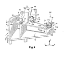
figure 4 représente une vue partielle en perspective d'un dispositif d'accrochage reliant un moteur et une voilure d'aéronef, selon un second mode de réalisation préféré de la présente invention.
- the
figure 1 is a perspective view of a coupling device connecting a motor and an aircraft wing, according to a first preferred embodiment of the present invention; - the
figure 2 represents an enlarged and exploded view in perspective of a part of the front attachment of the attachment device of thefigure 1 ; - the
figure 3 represents an enlarged and exploded view in perspective of the rear attachment of the attachment device of thefigure 1 ; and - the
figure 4 is a partial perspective view of a coupling device connecting a motor and an aircraft wing, according to a second preferred embodiment of the present invention.
En référence à la
Dans toute la description qui va suivre, par convention, on appelle X la direction parallèle à un axe longitudinal 5 du moteur 2, Y la direction orientée transversalement par rapport à l'aéronef, et Z la direction verticale, ces trois directions étant orthogonales entre-elles. Ainsi, il est à comprendre que les directions X, Y et Z correspondant respectivement à des directions longitudinale, transversale et de hauteur, à la fois pour l'aéronef et pour le moteur 2.Throughout the following description, by convention, X is the direction parallel to a
Il est précisé que l'axe longitudinal 5 du moteur 2 est à comprendre comme étant l'axe longitudinal du carter moteur, et non l'axe longitudinal de son hélice propulsive 7.It is specified that the
D'autre part, les termes « avant » et « arrière » sont à considérer par rapport à une direction d'avancement de l'aéronef rencontrée suite à la poussée exercée par les moteurs 2, cette direction étant représentée schématiquement par la flèche 6.On the other hand, the terms "front" and "rear" are to be considered in relation to a direction of advancement of the aircraft encountered following the thrust exerted by the
Sur la
De la même manière, la structure rigide 8 étant similaire à celles rencontrées dans les dispositifs de l'art antérieur, et présentant de toute façon une conception spécifique et différente en fonction de la nature du moteur qu'elle doit suspendre, elle ne sera par conséquent pas davantage décrite.In the same way, the
En revanche, les moyens d'accrochage 10, situés globalement vers l'arrière de la structure rigide 8, et plus précisément au niveau d'un caisson sous-aile 12 dans le cas représenté d'une structure rigide d'un turbopropulseur, sont spécifiques à la présente invention, et vont donc être présentés de façon détaillée ci-dessous.On the other hand, the attachment means 10, located generally towards the rear of the
De façon générale, les moyens d'attache 10 sont constitués d'une attache avant 14, ainsi que d'une attache arrière 16. Comme cela sera exposé en détails ci-dessous, l'attache avant 14 relie un longeron supérieur 18 du caisson sous-aile 12 de la structure rigide 8, à un longeron vertical avant 20 faisant partie intégrante de la structure de l'aile 4 et s'étendant sensiblement selon une direction principale longitudinale (non représentée) de cette même aile 4.In general, the attachment means 10 consist of a
D'autre part, l'attache arrière 16 relie une extrémité arrière du longeron supérieur 18 du caisson sous-aile 12, à un longeron horizontal intermédiaire (non représenté) faisant partie intégrante de la structure de l'aile 4 et s'étendant également sensiblement selon la direction principale longitudinale de cette même aile 4.On the other hand, the
Comme on peut l'apercevoir sur la
En référence plus spécifiquement à la
Deux manilles triangulaires 30 et 32, de préférence identiques et prenant grossièrement la forme d'un triangle équilatéral, sont respectivement agencées de part et d'autre de cette ferrure 24, également dans des plans XZ. Ainsi, la manille extérieure 30 et la manille intérieure 32 forment ensemble une paire de manilles triangulaires 34, dont les manilles 30,32 sont parallèles entre-elles. A ce titre, il est précisé que la paire de manilles triangulaires 34 pourrait également être réalisée à l'aide de manilles doubles, sans sortir du cadre de l'invention. Dans un tel cas, la paire de manilles 34 comporterait alors quatre manilles identiques réparties en deux ensembles de deux manilles triangulaires superposées, respectivement agencés de chaque côté de la ferrure 24.Two
Dans ce premier mode de réalisation préféré de la présente invention, la manille extérieure 30 est agencée de sorte que c'est l'une de ses bases 30a qui est montée sur la ferrure 24, cette base 30a étant orientée sensiblement selon la direction longitudinale X. De cette manière, on peut alors comprendre que la manille 30 est placée de sorte qu'elle s'étende verticalement vers le haut selon la direction Z, de sa base 30a, vers un sommet opposé 30b à cette base 30a.In this first preferred embodiment of the present invention, the
Ainsi, à proximité de chacun des deux sommets (non référencés) associés à cette base 30a, il est réalisé un trou traversant 36, orienté selon la direction transversale Y. De la même manière, la manille intérieure 32 est agencée de façon identique à celle de la manille extérieure 30, à savoir que c'est l'une de ses bases 32a qui est montée sur la ferrure 24, et que cette base 32a est orientée sensiblement selon la direction longitudinale X. Par conséquent, ici aussi, il est pratiqué un trou traversant 38 orienté selon la direction transversale Y, à proximité de chacun des deux sommets (non référencés) associés à cette base 32a.Thus, near each of the two vertices (not referenced) associated with this
Pour assurer la liaison entre la paire de manilles 34 et la ferrure 24, la demi-attache 14a comporte alors deux axes 40 et 42 orientés selon la direction transversale Y, et disposés dans un même plan horizontal XY. En effet, l'axe avant 40, de préférence double comme représenté sur la
Par ailleurs, la demi-attache 14a est pourvue d'une autre ferrure 44 orientée dans un plan vertical XZ et prenant la forme d'une nervure de la structure de l'aile 4, cette nervure 44 étant solidaire du longeron 20 comme cela est clairement visible sur la
Pour assurer la fixation de la paire de manilles triangulaires 34 sur cette ferrure 44, la manille extérieure 30 dispose d'un trou traversant 48 orienté selon la direction transversale Y, ce trou 48 étant pratiqué à proximité du sommet 30b opposé à la base 30a susmentionnée. De manière analogue, la manille intérieure 32 dispose d'un trou traversant 50 orienté selon la direction transversale Y, ce trou 50 étant pratiqué à proximité d'un sommet 32b opposé à la base 32a indiquée précédemment.To secure the pair of
Avec un tel agencement, un axe supérieur 52 orienté selon la direction transversale Y, disposé au-dessus des axes 40 et 42 et étant de préférence double comme représenté sur la
Comme cela a été mentionné ci-dessus, la demi-attache 14b ne va pas être davantage décrite, dans la mesure où seule la longueur selon la direction X de sa ferrure 54 interposée entre le longeron 20 et la paire de manilles triangulaires (non référencée), diffère par rapport à la longueur selon la direction X de la ferrure 44 de la demi-attache 14a. Bien entendu, cela s'explique par le positionnement du longeron 20 de l'aile 4, qui se trouve dans un plan vertical incliné par rapport à un plan YZ.As mentioned above, the half-
En référence à présent à la
Cette ferrure 56 est percée de deux trous traversants 60 (un seul étant visible sur la
Deux manilles triangulaires 62 et 64, de préférence identiques et prenant grossièrement la forme d'un triangle équilatéral, sont respectivement agencées de part et d'autre de cette ferrure 56, également dans des plans YZ. Ainsi, la manille avant 62 et la manille arrière 64 forment ensemble une paire de manilles triangulaires 66, dont les manilles 62,64 sont parallèles entre-elles. A ce titre, il est précisé que la paire de manilles triangulaires 66 pourrait ici aussi être réalisée à l'aide de manilles doubles, sans sortir du cadre de l'invention.Two
Dans ce premier mode de réalisation préféré de la présente invention, la manille avant 62 est agencée de sorte que c'est l'une de ses bases 62a qui est montée sur la ferrure 56, cette base 62a étant orientée sensiblement selon la direction transversale Y. De cette manière, on peut alors comprendre que la manille 62 est placée de sorte qu'elle s'étende verticalement vers le haut selon la direction Z, de sa base 62a, vers un sommet opposé 62b à cette base 62a.In this first preferred embodiment of the present invention, the
Ainsi, à proximité de chacun des deux sommets (non référencés) associés à cette base 62a, il est réalisé un trou traversant 68, orienté selon la direction longitudinale X. De la même manière, la manille arrière 64 est agencée de façon identique à celle de la manille avant 62, à savoir que c'est l'une de ses bases 64a qui est montée sur la ferrure 56, et que cette base 64a est orientée sensiblement selon la direction transversale Y. Par conséquent, ici aussi, il est pratiqué un trou traversant 70 orienté selon la direction longitudinale X, à proximité de chacun des deux sommets (non référencés) associés à cette base 64a.Thus, near each of the two vertices (not referenced) associated with this
Pour assurer la liaison entre la paire de manilles 66 et la ferrure 56, l'attache arrière 16 comporte alors deux axes latéraux 72 et 74 orientés selon la direction longitudinale X, et disposés dans un même plan horizontal XY. En effet, l'axe latéral 72, de préférence double comme représenté sur la
Par ailleurs, l'attache arrière 16 est pourvue d'une autre ferrure 76 orientée globalement dans un plan vertical YZ et se prolongeant vers le haut par une plaque horizontale 78, cette plaque 78 étant solidaire du longeron intermédiaire horizontal de l'aile 4. Par conséquent, la ferrure 76 traverse un revêtement d'intrados 22 de l'aile 4.Furthermore, the
Dans une partie inférieure, cette ferrure 76 est percée d'un trou unique traversant 80, orienté selon la direction longitudinale X de l'aéronef.In a lower part, this
Pour assurer la fixation de la paire de manilles triangulaires 66 sur cette ferrure 76, la manille avant 62 dispose d'un trou traversant 82 orienté selon la direction longitudinale X, ce trou 82 étant pratiqué à proximité du sommet 62b opposé à la base 62a susmentionnée. De manière analogue, la manille arrière 64 dispose d'un trou traversant 84 orienté selon la direction longitudinale X, ce trou 84 étant pratiqué à proximité d'un sommet 64b opposé à la base 64a indiquée précédemment.To secure the pair of
Avec un tel agencement, un axe supérieur 86, disposé au-dessus des axes latéraux 72,74 et étant de préférence double comme représenté sur la
Dans cet agencement isostatique de la présente invention, les efforts longitudinaux (poussée, inverseurs) sont transmis par l'attache avant 14. Les efforts transversaux sont transmis par l'attache arrière 16, tandis que les efforts selon la direction verticale passent simultanément par l'attache avant 14 et l'attache arrière 16. Il est noté qu'avec une telle configuration, les efforts longitudinaux transitent directement par les nervures 44 et 54 de la structure de l'aile 4, ces nervures 44 et 54 étant situées globalement vers l'arrière par rapport aux demi-attaches 14a,14b. De plus, il est donc à comprendre que chaque demi-attache 14a, 14b est conçue de façon à reprendre et faire passer les efforts selon les directions X et Z, et non selon la direction Y. Parallèlement, l'attache arrière 16 est conçue de façon à reprendre et faire passer les efforts selon les directions Y et Z, et non selon la direction X.In this isostatic arrangement of the present invention, the longitudinal forces (thrust, inverters) are transmitted by the
Par ailleurs, le moment selon l'axe longitudinal est repris dans la direction verticale par les deux demi-attaches 14a,14b de l'attache avant 14, et le moment selon l'axe transversal est repris également dans la direction verticale par l'ensemble formé par les attaches avant 14 et arrière 16. Enfin, le moment selon l'axe vertical est repris dans la direction longitudinale par les deux demi-attaches 14a,14b de l'attache avant 14.Furthermore, the moment along the longitudinal axis is taken up in the vertical direction by the two half-
En référence à la
Ainsi, on peut voir sur cette
Effectivement, si l'ensemble des manilles triangulaires 30,32,62,64 du dispositif 1 étaient situées de sorte qu'elles s'étendent verticalement vers le haut, de l'une de leurs bases vers le sommet opposé à cette base, ces mêmes manilles triangulaires du dispositif 100 s'étendent ici également verticalement, mais de l'une de leurs bases vers le sommet opposé à cette base en allant vers le bas. En d'autres termes, les manilles triangulaires des paires de manilles 34 et 66 ont été pivotées de 180° respectivement selon la direction transversale Y et la direction longitudinale X, par rapport à leurs positions occupées dans le premier mode de réalisation préféré.Indeed, if the set of
Par conséquent, comme cela est clairement visible sur la
D'autre part, les bases 62a et 64a de l'attache arrière 16 sont reliées à la ferrure 76 solidaire de l'aile 4, et les sommets opposés 62b et 64b sont reliés à la ferrure 56 solidaire de la structure rigide 8.On the other hand, the
Bien entendu, diverses modifications peuvent être apportées par l'homme du métier aux dispositifs d'accrochage 1 et 100 qui viennent d'être décrits, uniquement à titre d'exemples non limitatifs.Of course, various modifications may be made by those skilled in the art to the
Claims (10)
- Hanging device (1,100) connecting an engine (2) to a aircraft wing (4), said device comprising a rigid structure (8) and hanging equipment (10) interposed between said rigid structure (8) and the wing (4), said hanging equipment (10) comprising a forward attachment (14) and a rear attachment (16) including at least one triangular shackle (62,64) placed in a vertical plane aligned along a transverse direction (Y) of the aircraft, said forward attachment 14 being constituted of two half-attachements (14a, 14b) arranged respectively on one side and the other of a vertical plane passing through a longitudinal axis (5) of the engine (2), characterised by the fact that each half-attachment (14a, 14b) comprises at least one triangular shackle (30, 32) placed in a vertical plane aligned along a longitudinal direction (X) of the aircraft, and so that said hanging equipment (10) is made up exclusively of the aforementioned forward (14) and rear (16) attachments.
- Hanging device (1, 100) for an engine (2) as claimed in claim 1 characterized by each of two half-attachements (14a, 14b) being designed so as to take up forces along the longitudinal direction (X) and along a vertical direction (Z) of said aircraft, and by said rear attachement (16) being designed so as to take up forces along the transverse direction (Y) and along the vertical direction (Z).
- Hanging device (1, 100) for an engine (2) as claimed in claim 1 characterised by the fact that the rear attachment (16) is made up of a pair of triangular shackles (66) placed in vertical planes aligned along the transverse direction (Y) of the aircraft, arid so that the forward attachment (14) is made up, on one side and the other of the vertical plane passing through the longitudinal axis (5) of the engine (2), of a pair of triangular shackles (34) placed in vertical planes aligned along the longitudinal direction (X) of the aircraft.
- Hanging device (1,100) for an engine (2) as claimed in claim 3, characterised by the fact that the aforementioned pair of triangular shackles (66) on the rear attachment (16) are connected to the rigid structure (8) and to the wing (4) of the aircraft using pins (72, 74, 86) aligned along the longitudinal direction (X) of the aircraft.
- Hanging device (1,100) for an engine (2) as claimed in claim 3 or in claim 4, characterised by the fact that each of the two pairs of triangular shackles (34) on the forward attachment(14) is connected to the rigid structure (8) and to the wing (4) of the aircraft using pins (40, 42, 52) aligned along the transverse direction (Y) of the aircraft.
- Hanging device (1,100) for an engine (2) as claimed in any of claims 3 to 5, characterised by the fact that said rear attachment (16) is furthermore comprising a bracket (56) integral with the rigid structure (8), connected to the aforementioned pair of shackles (66) by at last one pin (70, 72) aligned in the longitudinal direction (X) of the aircraft, and by the fact that the aforementioned rear attachment (16) is also comprising a bracket (76) integral with the wing (4), connected to the aforementioned pair of triangular shackles (66) by at least one pin (86) aligned in the longitudinal direction (X) of this aircraft.
- Hanging device (1,100) for an engine (2) as claimed in any of claims 3 to 6, characterised by the fact that the aforementioned forward attachment (14) is furthermore comprising two brackets (24) integral with the rigid structure (8), with each bracket (24) connected to the aforementioned pair of triangular shackles (34) by at last one pin (40,42) aligned in the transverse direction (Y) of the aircraft, and by the fact that the aforementioned forward attachment (14) is also comprising two brackets (44,54) integral with the wing (4), with each bracket (44,54) being connected to one the two pairs of triangular shackles (34) by at least one pin (52) aligned in the transverse direction (Y) of this aircraft.
- Hanging device (1,100) for an engine (2) as claimed in any of the previous claims, characterised by the fact that each pair of triangular shackles (30,32,62,64) is connected to the rigid structure (8) and to the wing (4) of the aircraft using three pins (40,42,52,72,74,86) passing through it, close, respectively, to each of its three apices (30b, 32b, 62b, 64b) .
- Hanging device (1) for an engine (2) as claimed in any of the previous claims, characterised by the fact that at least one triangular shackle (30,32,62,64) is connected to the rigid structure (8) by one of its bases (30a,32a,62a,64a), and to the wing (4) by the apex (30b,32b,62b,64b) opposite this base.
- Hanging device (100) for an engine as claimed in any of the previous claims 1 to 8, characterised by the fact that at least one triangular shackle (30,32,62,64) is connected to the rigid structure (8) by one of its apices (30b,32b,62b,64b), and to the wing (4) by the base (30a, 32a, 62a, 64a) opposite this apex.
Applications Claiming Priority (2)
| Application Number | Priority Date | Filing Date | Title |
|---|---|---|---|
| FR0350906 | 2003-11-25 | ||
| FR0350906A FR2862610B1 (en) | 2003-11-25 | 2003-11-25 | ATTACHING DEVICE CONNECTING AN ENGINE AND AN AIRCRAFT SAIL |
Publications (2)
| Publication Number | Publication Date |
|---|---|
| EP1535837A1 EP1535837A1 (en) | 2005-06-01 |
| EP1535837B1 true EP1535837B1 (en) | 2008-07-16 |
Family
ID=34451745
Family Applications (1)
| Application Number | Title | Priority Date | Filing Date |
|---|---|---|---|
| EP04106018A Active EP1535837B1 (en) | 2003-11-25 | 2004-11-23 | Engine suspension attachment device of an engine to an aircraft wing |
Country Status (6)
| Country | Link |
|---|---|
| US (1) | US7121504B2 (en) |
| EP (1) | EP1535837B1 (en) |
| AT (1) | ATE401242T1 (en) |
| CA (1) | CA2486500C (en) |
| DE (1) | DE602004015048D1 (en) |
| FR (1) | FR2862610B1 (en) |
Families Citing this family (21)
| Publication number | Priority date | Publication date | Assignee | Title |
|---|---|---|---|---|
| FR2862611B1 (en) * | 2003-11-25 | 2007-03-09 | Airbus France | DEVICE FOR ATTACHING AN ENGINE UNDER AN AIRCRAFT SAIL |
| FR2862944B1 (en) * | 2003-12-01 | 2006-02-24 | Airbus France | DEVICE FOR ATTACHING A TURBOPROPULSER UNDER AN AIRCRAFT VESSEL |
| FR2889163B1 (en) * | 2005-07-29 | 2007-09-07 | Airbus France Sas | AIRCRAFT ASSEMBLY COMPRISING A SAILING ELEMENT AND A HITCHING MAT |
| FR2915178B1 (en) * | 2007-04-23 | 2009-07-10 | Airbus France Sa | ATTACHMENT OF A MAT BOX ON A SAIL, PINCING A SIDE PANEL OF THE HOUSING |
| GB0722772D0 (en) * | 2007-11-21 | 2008-01-02 | Airbus Uk Ltd | Aircraft engine pylon attachment |
| US8342444B2 (en) * | 2008-12-16 | 2013-01-01 | The Boeing Company | Fail safe extended torque box strut-to-wing mount |
| FR2950860B1 (en) * | 2009-10-01 | 2011-12-09 | Airbus Operations Sas | DEVICE FOR CONNECTING AN ENGINE TO AN AIRCRAFT MAT |
| FR2958267B1 (en) * | 2010-04-02 | 2012-03-23 | Airbus Operations Sas | AXIS SYSTEM FOR LINK ASSEMBLY OF MAT-REACTOR UNDER AN AIRCRAFT VESSEL |
| FR2958262B1 (en) * | 2010-04-02 | 2012-03-23 | Airbus Operations Sas | AXIS SYSTEM FOR LINK ASSEMBLY OF MAT-REACTOR UNDER AN AIRCRAFT VESSEL |
| FR2958263B1 (en) * | 2010-04-02 | 2012-03-23 | Airbus Operations Sas | AXIS SYSTEM FOR LINK ASSEMBLY OF MAT-REACTOR UNDER AN AIRCRAFT VESSEL |
| FR2958264B1 (en) * | 2010-04-02 | 2012-03-23 | Airbus Operations Sas | AXIS SYSTEM FOR LINK ASSEMBLY OF MAT-REACTOR UNDER AN AIRCRAFT VESSEL |
| FR2958265B1 (en) * | 2010-04-02 | 2012-03-23 | Airbus Operations Sas | AXIS SYSTEM FOR LINK ASSEMBLY OF MAT-REACTOR UNDER AN AIRCRAFT VESSEL |
| FR2958266B1 (en) * | 2010-04-02 | 2012-03-23 | Airbus Operations Sas | AXIS SYSTEM FOR LINK ASSEMBLY OF MAT-REACTOR UNDER AN AIRCRAFT VESSEL |
| EP3024729B1 (en) | 2013-07-26 | 2022-04-27 | MRA Systems, LLC | Aircraft engine pylon |
| EP3071481B1 (en) | 2013-11-18 | 2020-01-08 | LORD Corporation | Turboprop engine attachment systems and methods |
| US9238511B2 (en) | 2014-03-04 | 2016-01-19 | Mra Systems, Inc. | Engine pylon structure |
| FR3065441B1 (en) * | 2017-04-19 | 2019-07-05 | Airbus Operations | AIRCRAFT ASSEMBLY COMPRISING A PRIMARY STRUCTURE OF A COUPLING MAT FIXED TO A SAILBOX USING A BOLT CONNECTION |
| FR3080096B1 (en) * | 2018-04-11 | 2020-03-13 | Airbus Operations | AIRCRAFT ENGINE MOUNT COMPRISING INCLINED FASTENERS, AIRCRAFT COMPRISING SAID ENGINE MOUNT AND METHOD FOR ATTACHING AN ENGINE TO AN AIRCRAFT MAT USING SAID ENGINE MOUNT |
| FR3098193B1 (en) * | 2019-07-03 | 2022-02-11 | Airbus Operations Sas | Aircraft comprising a rear wing attachment having at least one pin secured to a primary structure of a mast |
| GB2586476A (en) * | 2019-08-20 | 2021-02-24 | Airbus Operations Ltd | Aircraft wing-pylon connection |
| FR3120603A1 (en) * | 2021-03-11 | 2022-09-16 | Airbus Operations (S.A.S.) | Aircraft mast comprising a tubular primary structure incorporating at least one double-skin pipe and aircraft comprising at least one such mast |
Family Cites Families (3)
| Publication number | Priority date | Publication date | Assignee | Title |
|---|---|---|---|---|
| US3042349A (en) * | 1959-11-13 | 1962-07-03 | Gen Electric | Removable aircraft engine mounting arrangement |
| FR2738034B1 (en) | 1995-08-23 | 1997-09-19 | Snecma | DEVICE FOR SUSPENDING A TURBOPROPELLER |
| FR2836672B1 (en) * | 2002-03-04 | 2004-06-04 | Airbus France | MATCH FOR HANGING AN ENGINE UNDER AN AIRCRAFT |
-
2003
- 2003-11-25 FR FR0350906A patent/FR2862610B1/en not_active Expired - Fee Related
-
2004
- 2004-11-23 AT AT04106018T patent/ATE401242T1/en not_active IP Right Cessation
- 2004-11-23 US US10/994,483 patent/US7121504B2/en active Active
- 2004-11-23 CA CA2486500A patent/CA2486500C/en not_active Expired - Fee Related
- 2004-11-23 EP EP04106018A patent/EP1535837B1/en active Active
- 2004-11-23 DE DE602004015048T patent/DE602004015048D1/en active Active
Also Published As
| Publication number | Publication date |
|---|---|
| EP1535837A1 (en) | 2005-06-01 |
| FR2862610B1 (en) | 2007-03-23 |
| CA2486500A1 (en) | 2005-05-25 |
| ATE401242T1 (en) | 2008-08-15 |
| US7121504B2 (en) | 2006-10-17 |
| FR2862610A1 (en) | 2005-05-27 |
| CA2486500C (en) | 2013-01-08 |
| US20050151008A1 (en) | 2005-07-14 |
| DE602004015048D1 (en) | 2008-08-28 |
Similar Documents
| Publication | Publication Date | Title |
|---|---|---|
| EP1535838B1 (en) | Suspension device for an engine unter an aircraft wing | |
| EP1535837B1 (en) | Engine suspension attachment device of an engine to an aircraft wing | |
| EP1910167B1 (en) | Assembly for aircraft comprising a wing system element as well as an attachment mast | |
| EP1773660B1 (en) | Aircraft engine unit | |
| CA2697380C (en) | Cradle for holding a fan coil mounted on the attachment pylon and on the nacelle air intake | |
| EP2137072B1 (en) | Device for attaching an aircraft engine and aircraft comprising at least one such device | |
| FR2903383A1 (en) | Aircraft`s jet engine locking device, has mechanical connection with clearance between rear end of rods and support fitting integrated to box, where connection is placed in rear end mounted on rudder bar of thrust reacting device | |
| FR2891244A1 (en) | ENGINE ATTACHING MAT FOR AN AIRCRAFT | |
| EP2170704A1 (en) | Device for coupling an aircraft engine and method for mounting an aircraft engine by means of such a device | |
| FR2903666A1 (en) | AIRCRAFT ENGINE ASSEMBLY COMPRISING AERODYNAMIC JOINT COVERAGE MOUNTED ON TWO SEPARATE ELEMENTS | |
| CA2839336A1 (en) | Structure for mounting a turbine engine | |
| EP1480876B1 (en) | Engine pylon suspension attachment of an engine under an aircraft wing section | |
| FR2964364A1 (en) | AIRCRAFT TURBOJET ENGINEERING MACHINE COMPRISING FRONT VANE FRONT FASTENERS | |
| EP1538081B1 (en) | Suspension device for an engine under an aircraft wing | |
| FR2916736A1 (en) | APPARATUS FOR HANDLING AN AIRCRAFT TURBOPROPULSER COMPRISING HYDRAULIC FASTENING MEANS. | |
| FR2891247A1 (en) | Aircraft assembly, has engine mounting structure with rigid structure forming shell with rear closing element, and rigid structure mounted on wing element so that wing element is supported against front longeron | |
| FR2905932A1 (en) | ARRANGEMENT FOR ATTACHING DEVICE FOR ATTACHING AN AIRCRAFT ENGINE | |
| EP1535839B1 (en) | Underwing aircraft engine mounting structure | |
| EP3505448B1 (en) | Assembly for aircraft comprising a mounting strut primary structure attached to a wing box by compact fasteners in the leading edge area | |
| FR2887522A1 (en) | Aircraft shipset, has turboshaft engine fixing mast with units to fix box forming rigid structure under box forming aerofoil unit, where fixing units have fastener with insert fitting placed inside structure and box forming aerofoil unit | |
| FR3065442A1 (en) | AIRCRAFT ENGINE ASSEMBLY COMPRISING A FRONT ENGINE ATTACHMENT INTEGRATED WITH THE BOX OF THE ATTACHING MAT | |
| EP3437999A1 (en) | Light primary structure for aircraft engine mounting strut |
Legal Events
| Date | Code | Title | Description |
|---|---|---|---|
| PUAI | Public reference made under article 153(3) epc to a published international application that has entered the european phase |
Free format text: ORIGINAL CODE: 0009012 |
|
| AK | Designated contracting states |
Kind code of ref document: A1 Designated state(s): AT BE BG CH CY CZ DE DK EE ES FI FR GB GR HU IE IS IT LI LU MC NL PL PT RO SE SI SK TR |
|
| AX | Request for extension of the european patent |
Extension state: AL HR LT LV MK YU |
|
| RIN1 | Information on inventor provided before grant (corrected) |
Inventor name: MACHADO, STEPHANE Inventor name: DEL BLANCO, ANTHONY Inventor name: MARTIN, YVON Inventor name: CASSAGNE, JEROEME Inventor name: CHAMBREUIL, ARNAUD |
|
| 17P | Request for examination filed |
Effective date: 20050715 |
|
| AKX | Designation fees paid |
Designated state(s): AT BE BG CH CY CZ DE DK EE ES FI FR GB GR HU IE IS IT LI LU MC NL PL PT RO SE SI SK TR |
|
| GRAP | Despatch of communication of intention to grant a patent |
Free format text: ORIGINAL CODE: EPIDOSNIGR1 |
|
| RIN1 | Information on inventor provided before grant (corrected) |
Inventor name: DEL BLANCO, ANTHONY Inventor name: MACHADO, STEPHANE Inventor name: CASSAGNE, JEROME Inventor name: CHAMBREUIL, ARNAUD Inventor name: MARTIN, YVON |
|
| RTI1 | Title (correction) |
Free format text: ENGINE SUSPENSION ATTACHMENT DEVICE OF AN ENGINE TO AN AIRCRAFT WING |
|
| GRAS | Grant fee paid |
Free format text: ORIGINAL CODE: EPIDOSNIGR3 |
|
| GRAA | (expected) grant |
Free format text: ORIGINAL CODE: 0009210 |
|
| AK | Designated contracting states |
Kind code of ref document: B1 Designated state(s): AT BE BG CH CY CZ DE DK EE ES FI FR GB GR HU IE IS IT LI LU MC NL PL PT RO SE SI SK TR |
|
| REG | Reference to a national code |
Ref country code: GB Ref legal event code: FG4D Free format text: NOT ENGLISH |
|
| REG | Reference to a national code |
Ref country code: CH Ref legal event code: EP |
|
| REF | Corresponds to: |
Ref document number: 602004015048 Country of ref document: DE Date of ref document: 20080828 Kind code of ref document: P |
|
| REG | Reference to a national code |
Ref country code: IE Ref legal event code: FG4D Free format text: LANGUAGE OF EP DOCUMENT: FRENCH |
|
| REG | Reference to a national code |
Ref country code: SE Ref legal event code: TRGR |
|
| NLV1 | Nl: lapsed or annulled due to failure to fulfill the requirements of art. 29p and 29m of the patents act | ||
| PG25 | Lapsed in a contracting state [announced via postgrant information from national office to epo] |
Ref country code: ES Free format text: LAPSE BECAUSE OF FAILURE TO SUBMIT A TRANSLATION OF THE DESCRIPTION OR TO PAY THE FEE WITHIN THE PRESCRIBED TIME-LIMIT Effective date: 20081027 Ref country code: PT Free format text: LAPSE BECAUSE OF FAILURE TO SUBMIT A TRANSLATION OF THE DESCRIPTION OR TO PAY THE FEE WITHIN THE PRESCRIBED TIME-LIMIT Effective date: 20081216 Ref country code: IS Free format text: LAPSE BECAUSE OF FAILURE TO SUBMIT A TRANSLATION OF THE DESCRIPTION OR TO PAY THE FEE WITHIN THE PRESCRIBED TIME-LIMIT Effective date: 20081116 Ref country code: NL Free format text: LAPSE BECAUSE OF FAILURE TO SUBMIT A TRANSLATION OF THE DESCRIPTION OR TO PAY THE FEE WITHIN THE PRESCRIBED TIME-LIMIT Effective date: 20080716 |
|
| PG25 | Lapsed in a contracting state [announced via postgrant information from national office to epo] |
Ref country code: SI Free format text: LAPSE BECAUSE OF FAILURE TO SUBMIT A TRANSLATION OF THE DESCRIPTION OR TO PAY THE FEE WITHIN THE PRESCRIBED TIME-LIMIT Effective date: 20080716 Ref country code: FI Free format text: LAPSE BECAUSE OF FAILURE TO SUBMIT A TRANSLATION OF THE DESCRIPTION OR TO PAY THE FEE WITHIN THE PRESCRIBED TIME-LIMIT Effective date: 20080716 Ref country code: AT Free format text: LAPSE BECAUSE OF FAILURE TO SUBMIT A TRANSLATION OF THE DESCRIPTION OR TO PAY THE FEE WITHIN THE PRESCRIBED TIME-LIMIT Effective date: 20080716 Ref country code: BG Free format text: LAPSE BECAUSE OF FAILURE TO SUBMIT A TRANSLATION OF THE DESCRIPTION OR TO PAY THE FEE WITHIN THE PRESCRIBED TIME-LIMIT Effective date: 20081016 |
|
| REG | Reference to a national code |
Ref country code: IE Ref legal event code: FD4D |
|
| PG25 | Lapsed in a contracting state [announced via postgrant information from national office to epo] |
Ref country code: DK Free format text: LAPSE BECAUSE OF FAILURE TO SUBMIT A TRANSLATION OF THE DESCRIPTION OR TO PAY THE FEE WITHIN THE PRESCRIBED TIME-LIMIT Effective date: 20080716 Ref country code: EE Free format text: LAPSE BECAUSE OF FAILURE TO SUBMIT A TRANSLATION OF THE DESCRIPTION OR TO PAY THE FEE WITHIN THE PRESCRIBED TIME-LIMIT Effective date: 20080716 Ref country code: IE Free format text: LAPSE BECAUSE OF FAILURE TO SUBMIT A TRANSLATION OF THE DESCRIPTION OR TO PAY THE FEE WITHIN THE PRESCRIBED TIME-LIMIT Effective date: 20080716 |
|
| PLBE | No opposition filed within time limit |
Free format text: ORIGINAL CODE: 0009261 |
|
| STAA | Information on the status of an ep patent application or granted ep patent |
Free format text: STATUS: NO OPPOSITION FILED WITHIN TIME LIMIT |
|
| PG25 | Lapsed in a contracting state [announced via postgrant information from national office to epo] |
Ref country code: RO Free format text: LAPSE BECAUSE OF FAILURE TO SUBMIT A TRANSLATION OF THE DESCRIPTION OR TO PAY THE FEE WITHIN THE PRESCRIBED TIME-LIMIT Effective date: 20080716 Ref country code: CZ Free format text: LAPSE BECAUSE OF FAILURE TO SUBMIT A TRANSLATION OF THE DESCRIPTION OR TO PAY THE FEE WITHIN THE PRESCRIBED TIME-LIMIT Effective date: 20080716 Ref country code: SK Free format text: LAPSE BECAUSE OF FAILURE TO SUBMIT A TRANSLATION OF THE DESCRIPTION OR TO PAY THE FEE WITHIN THE PRESCRIBED TIME-LIMIT Effective date: 20080716 |
|
| BERE | Be: lapsed |
Owner name: AIRBUS FRANCE Effective date: 20081130 |
|
| 26N | No opposition filed |
Effective date: 20090417 |
|
| PG25 | Lapsed in a contracting state [announced via postgrant information from national office to epo] |
Ref country code: MC Free format text: LAPSE BECAUSE OF NON-PAYMENT OF DUE FEES Effective date: 20081130 |
|
| REG | Reference to a national code |
Ref country code: CH Ref legal event code: PL |
|
| PG25 | Lapsed in a contracting state [announced via postgrant information from national office to epo] |
Ref country code: BE Free format text: LAPSE BECAUSE OF NON-PAYMENT OF DUE FEES Effective date: 20081130 |
|
| PG25 | Lapsed in a contracting state [announced via postgrant information from national office to epo] |
Ref country code: LI Free format text: LAPSE BECAUSE OF NON-PAYMENT OF DUE FEES Effective date: 20081130 Ref country code: CH Free format text: LAPSE BECAUSE OF NON-PAYMENT OF DUE FEES Effective date: 20081130 |
|
| PG25 | Lapsed in a contracting state [announced via postgrant information from national office to epo] |
Ref country code: PL Free format text: LAPSE BECAUSE OF FAILURE TO SUBMIT A TRANSLATION OF THE DESCRIPTION OR TO PAY THE FEE WITHIN THE PRESCRIBED TIME-LIMIT Effective date: 20080716 |
|
| PG25 | Lapsed in a contracting state [announced via postgrant information from national office to epo] |
Ref country code: CY Free format text: LAPSE BECAUSE OF FAILURE TO SUBMIT A TRANSLATION OF THE DESCRIPTION OR TO PAY THE FEE WITHIN THE PRESCRIBED TIME-LIMIT Effective date: 20080716 Ref country code: HU Free format text: LAPSE BECAUSE OF FAILURE TO SUBMIT A TRANSLATION OF THE DESCRIPTION OR TO PAY THE FEE WITHIN THE PRESCRIBED TIME-LIMIT Effective date: 20090117 Ref country code: LU Free format text: LAPSE BECAUSE OF NON-PAYMENT OF DUE FEES Effective date: 20081123 |
|
| PG25 | Lapsed in a contracting state [announced via postgrant information from national office to epo] |
Ref country code: TR Free format text: LAPSE BECAUSE OF FAILURE TO SUBMIT A TRANSLATION OF THE DESCRIPTION OR TO PAY THE FEE WITHIN THE PRESCRIBED TIME-LIMIT Effective date: 20080716 |
|
| PG25 | Lapsed in a contracting state [announced via postgrant information from national office to epo] |
Ref country code: GR Free format text: LAPSE BECAUSE OF FAILURE TO SUBMIT A TRANSLATION OF THE DESCRIPTION OR TO PAY THE FEE WITHIN THE PRESCRIBED TIME-LIMIT Effective date: 20081017 |
|
| REG | Reference to a national code |
Ref country code: GB Ref legal event code: 732E Free format text: REGISTERED BETWEEN 20110721 AND 20110727 |
|
| REG | Reference to a national code |
Ref country code: FR Ref legal event code: CD Owner name: AIRBUS HOLDING, FR Effective date: 20110916 Ref country code: FR Ref legal event code: CA Effective date: 20110916 Ref country code: FR Ref legal event code: TP Owner name: AIRBUS HOLDING, FR Effective date: 20110913 Ref country code: FR Ref legal event code: CJ Effective date: 20110916 |
|
| REG | Reference to a national code |
Ref country code: DE Ref legal event code: R082 Ref document number: 602004015048 Country of ref document: DE Representative=s name: HENKEL, BREUER & PARTNER, DE |
|
| REG | Reference to a national code |
Ref country code: DE Ref legal event code: R081 Ref document number: 602004015048 Country of ref document: DE Owner name: AIRBUS OPERATIONS SAS, FR Free format text: FORMER OWNER: AIRBUS FRANCE, TOULOUSE, FR Effective date: 20120326 Ref country code: DE Ref legal event code: R082 Ref document number: 602004015048 Country of ref document: DE Representative=s name: PATENTANWAELTE HENKEL, BREUER & PARTNER, DE Effective date: 20120326 |
|
| PGFP | Annual fee paid to national office [announced via postgrant information from national office to epo] |
Ref country code: SE Payment date: 20121120 Year of fee payment: 9 |
|
| REG | Reference to a national code |
Ref country code: SE Ref legal event code: EUG |
|
| PG25 | Lapsed in a contracting state [announced via postgrant information from national office to epo] |
Ref country code: SE Free format text: LAPSE BECAUSE OF NON-PAYMENT OF DUE FEES Effective date: 20131124 |
|
| REG | Reference to a national code |
Ref country code: FR Ref legal event code: PLFP Year of fee payment: 12 |
|
| REG | Reference to a national code |
Ref country code: FR Ref legal event code: PLFP Year of fee payment: 13 |
|
| REG | Reference to a national code |
Ref country code: FR Ref legal event code: PLFP Year of fee payment: 14 |
|
| PGFP | Annual fee paid to national office [announced via postgrant information from national office to epo] |
Ref country code: DE Payment date: 20191121 Year of fee payment: 16 |
|
| PGFP | Annual fee paid to national office [announced via postgrant information from national office to epo] |
Ref country code: IT Payment date: 20191128 Year of fee payment: 16 |
|
| PGFP | Annual fee paid to national office [announced via postgrant information from national office to epo] |
Ref country code: GB Payment date: 20191120 Year of fee payment: 16 |
|
| REG | Reference to a national code |
Ref country code: DE Ref legal event code: R119 Ref document number: 602004015048 Country of ref document: DE |
|
| GBPC | Gb: european patent ceased through non-payment of renewal fee |
Effective date: 20201123 |
|
| PG25 | Lapsed in a contracting state [announced via postgrant information from national office to epo] |
Ref country code: IT Free format text: LAPSE BECAUSE OF NON-PAYMENT OF DUE FEES Effective date: 20201123 |
|
| PG25 | Lapsed in a contracting state [announced via postgrant information from national office to epo] |
Ref country code: DE Free format text: LAPSE BECAUSE OF NON-PAYMENT OF DUE FEES Effective date: 20210601 Ref country code: GB Free format text: LAPSE BECAUSE OF NON-PAYMENT OF DUE FEES Effective date: 20201123 |
|
| PGFP | Annual fee paid to national office [announced via postgrant information from national office to epo] |
Ref country code: FR Payment date: 20231120 Year of fee payment: 20 |