EP1535677A1 - Press tool - Google Patents
Press tool Download PDFInfo
- Publication number
- EP1535677A1 EP1535677A1 EP03405848A EP03405848A EP1535677A1 EP 1535677 A1 EP1535677 A1 EP 1535677A1 EP 03405848 A EP03405848 A EP 03405848A EP 03405848 A EP03405848 A EP 03405848A EP 1535677 A1 EP1535677 A1 EP 1535677A1
- Authority
- EP
- European Patent Office
- Prior art keywords
- pressing
- press
- tool
- pressing jaw
- closed
- Prior art date
- Legal status (The legal status is an assumption and is not a legal conclusion. Google has not performed a legal analysis and makes no representation as to the accuracy of the status listed.)
- Granted
Links
Images


Classifications
-
- B—PERFORMING OPERATIONS; TRANSPORTING
- B25—HAND TOOLS; PORTABLE POWER-DRIVEN TOOLS; MANIPULATORS
- B25B—TOOLS OR BENCH DEVICES NOT OTHERWISE PROVIDED FOR, FOR FASTENING, CONNECTING, DISENGAGING OR HOLDING
- B25B27/00—Hand tools, specially adapted for fitting together or separating parts or objects whether or not involving some deformation, not otherwise provided for
- B25B27/02—Hand tools, specially adapted for fitting together or separating parts or objects whether or not involving some deformation, not otherwise provided for for connecting objects by press fit or detaching same
- B25B27/10—Hand tools, specially adapted for fitting together or separating parts or objects whether or not involving some deformation, not otherwise provided for for connecting objects by press fit or detaching same inserting fittings into hoses
-
- B—PERFORMING OPERATIONS; TRANSPORTING
- B21—MECHANICAL METAL-WORKING WITHOUT ESSENTIALLY REMOVING MATERIAL; PUNCHING METAL
- B21D—WORKING OR PROCESSING OF SHEET METAL OR METAL TUBES, RODS OR PROFILES WITHOUT ESSENTIALLY REMOVING MATERIAL; PUNCHING METAL
- B21D39/00—Application of procedures in order to connect objects or parts, e.g. coating with sheet metal otherwise than by plating; Tube expanders
- B21D39/04—Application of procedures in order to connect objects or parts, e.g. coating with sheet metal otherwise than by plating; Tube expanders of tubes with tubes; of tubes with rods
- B21D39/048—Application of procedures in order to connect objects or parts, e.g. coating with sheet metal otherwise than by plating; Tube expanders of tubes with tubes; of tubes with rods using presses for radially crimping tubular elements
Definitions
- the invention relates to a pressing tool, in particular for pressing of pipe ends, with at least two pressing jaw elements, which form an opening gap with opposite ends, the is essentially closed after pressing.
- Pressing tools of the type mentioned have long been known and especially for pressing pipe ends in the sanitary area used. For example, by plastic compression Water pipes are connected with fittings. The pressing jaws when pressing by hand or with a hydraulic Drive closed. During the pressing process, the opening gap closed between the free ends of the pressing jaw elements.
- the pressed pipe end is thereby out of round, which has different disadvantages. For example can by the non-circular cross-section of the compressed pipe the Sealing effect should not be optimal.
- a pressing tool would be desirable, with the one most perfect centric and ensures round compression at different pipe cross sections is.
- a pressing tool of the type mentioned is, for example EP 1 036 608 A of the applicant.
- the pressing tool is designed here as a press loop, the three pressing jaw elements which are hinged together are.
- This press loop is around the pipe end to be pressed placed and provisionally closed with a strap.
- a hydraulic drive which on the two outer Pressing jaw elements is applied, the press loop is closed.
- a similar pressing tool is from the EP 0 671 984 A has become known.
- a pressing tool which also is designed as a press loop. This has press inserts on, which are kept floating in the press jaws and which are moved during the pressing in the circumferential direction. At the Pressing first come the free ends of the press inserts to the plant, while at the other ends a movement gap remains. This should make it possible to pipes with nominal diameters over 50 to press.
- this pressing tool is constructive comparatively complex and consists of many individual parts.
- the invention is based on the object, a pressing tool of called type to create the above-mentioned difficulties avoids and inexpensive to produce with ease of use is.
- the task is in a generic pressing tool characterized solved that at least one pressing jaw element a support means has, when applied pressing tool and in not yet compressed state on the outside of the object to be pressed bears radially supporting and together during pressing is moved with the pressing jaw elements in the circumferential direction.
- pressing tool according to the invention When pressing tool according to the invention is to be pressed Object before the pressing process and during the pressing process supported or guided in the opening gap by said support element, so that the object can not move radially. In order to it is ensured that in the opening gap no bulge or protrude. Thus, a centric and round Pressing guaranteed. It has surprisingly been found that with the invention, the force required for pressing force or the energy consumption is much smaller than before. The Pressing can thus be used in particular with a pressing tool Hand drive easier and faster.
- the support element is attached directly to the pressing jaw element and can as a simple finger-shaped extension of this pressing jaw element be educated. Additional elements and in particular Press inserts and means for moving these press inserts are avoided.
- the inventive pressing tool is not much more expensive to manufacture than previous ones Pressing tools or press slings.
- the support means is fixed connected to the pressing jaw member and preferably on this formed.
- a pressing jaw element is a support element as an extension and the opposite with this cooperating Pressing jaw member has a recess, in which the Extension can enter when closing the pressing tool.
- the proppant or the extension in cross-section U-shaped is U-shaped.
- the pressing tool 1 shown in FIG. 1 is a so-called Press sling, the middle pressing jaw element 2 and two having outer pressing jaw elements 3 and 4.
- the pressing jaw element 2 is with two hinge joints 5 with the other Pressing jaw elements 3 and 4 hingedly connected.
- a bracket 11 is pivotally mounted, with which the Pressing tool 1 according to Figure 2 are closed provisionally can.
- the disclosure is also hereby referred to EP 1 036 608 A of Applicant referenced, in which in particular the function of this Ironing 11 is disclosed.
- the pressing jaw elements 2, 3 and 4 each have an inner side 20, 21 and 22, respectively, which form the pressing surfaces and the with closed pressing tool in cross-section a round and form closed pressing surface.
- the insides 20, 21 and 22 may have protruding ribs extending in the circumferential direction extend and during the pressing process in the outside of the bury the object to be pressed.
- the press tool 1 shown is, as mentioned, in particular a Pressing loop. In principle, such a press loop also have more than three pressing jaw elements.
- the inventive Press tool is not limited to a press sling, but can for example be designed as pressing tongs be, which has only two pressing jaw elements and is closed by hand or motor.
- the one to be pressed The subject matter is preferably a tube 14 and in particular a pipe of sanitary engineering, basically can with the inventive pressing tool but also other objects be pressed.
- This support part 8 is part of the Pressing jaw element 3 and in particular integrally formed on this. In principle, this support member 8 could also be otherwise be firmly connected to the pressing jaw element 3.
- the support part 8 is formed according to Figure 6 U-shaped and has two parallel to each other side wall 10 and one of these bridge-like connecting wall 26. This wall 26 has projecting ribs 18, and is corresponding in the circumferential direction the inside 20 bent in a circle, as the figure 1 recognize leaves.
- the ribs 18 correspond to ribs 27 of the pressing jaw elements 2, 3 and 4 and each form a continuation of this.
- the pressing jaw element 4 has at its free end 7 a recess 9, which are formed corresponding to the support part 8 is and which receives this support member 8 in the closed state. If the pressing tool 1 according to FIG. 3 is applied to a tube 14, but not yet closed, the support member 8 engages preferably slightly into the recess 8 a. In the area of Opening gap 19 is thus the pipe to be pressed 14 at his Outside supported by the support member 8 and can during pressing do not dodge radially. If now the pressing tool 1 is closed, Thus, the support member 8 is pushed into the recess 9. The wall 26 slides on the outside 28 along the pipe 14 to be pressed. The thickness of the wall 26 is comparatively small and is for example 1 to 3 mm.
- the tube 14 is in particular a plastically deformable water pipe with a core layer 14b Aluminum and two layers 14a and 14c bonded thereto made of plastic.
Abstract
Description
Die Erfindung betrifft ein Presswerkzeug, insbesondere zum Verpressen von Rohrenden, mit wenigstens zwei Pressbackenelementen, die mit gegenüberliegenden Enden einen Öffnungsspalt bilden, der nach dem Verpressen im Wesentlichen geschlossen ist.The invention relates to a pressing tool, in particular for pressing of pipe ends, with at least two pressing jaw elements, which form an opening gap with opposite ends, the is essentially closed after pressing.
Presswerkzeuge der genannten Art sind seit langem bekannt und werden insbesondere zum Verpressen von Rohrenden im Sanitärbereich verwendet. Beispielsweise können durch plastisches Verpressen Wasserrohre mit Fittings verbunden werden. Die Pressbacken werden beim Verpressen von Hand oder mit einem hydraulischen Antrieb geschlossen. Beim Pressvorgang wird der Öffnungsspalt zwischen den freien Enden der Pressbackenelemente geschlossen. In der Praxis hat sich nun gezeigt, dass sich beim Verpressen am Rohrende im Bereich des Öffnungsspaltes Aufstauchungen oder Wulste bilden können. Das verpresste Rohrende ist dadurch unrund, was verschiedene Nachteile hat. Beispielsweise kann durch den unrunden Querschnitt des verpressten Rohres die Dichtwirkung nicht optimal sein. Wünschbar wäre somit ein Presswerkzeug, mit dem eine möglichst vollkommende zentrische und runde Verpressung bei unterschiedlichen Rohrquerschnitten gewährleistet ist. Pressing tools of the type mentioned have long been known and especially for pressing pipe ends in the sanitary area used. For example, by plastic compression Water pipes are connected with fittings. The pressing jaws when pressing by hand or with a hydraulic Drive closed. During the pressing process, the opening gap closed between the free ends of the pressing jaw elements. In practice, it has now been shown that at Pressing at the end of the pipe in the area of the opening gap or bulges can form. The pressed pipe end is thereby out of round, which has different disadvantages. For example can by the non-circular cross-section of the compressed pipe the Sealing effect should not be optimal. Thus, a pressing tool would be desirable, with the one most perfect centric and ensures round compression at different pipe cross sections is.
Ein Presswerkzeug der genannten Gattung ist beispielsweise aus
der EP 1 036 608 A des Anmelders bekannt geworden. Das Presswerkzeug
ist hier als Pressschlinge ausgebildet, die drei Pressbackenelemente
aufweist, welche gelenkig miteinander verbunden
sind. Diese Pressschlinge wird um das zu verpressende Rohrende
gelegt und mit einem Bügel provisorisch geschlossen. Mittels eines
hydraulischen Antriebes, welcher an die beiden äusseren
Pressbackenelemente angelegt wird, wird die Pressschlinge geschlossen.
Ein ähnliches Presswerkzeug ist aus der
EP 0 671 984 A bekannt geworden.A pressing tool of the type mentioned is, for
In der EP 1 208 949 A ist ein Presswerkzeug offenbart, das ebenfalls
als Pressschlinge ausgebildet ist. Diese weist Presseinsätze
auf, die schwimmend in den Pressbacken gehalten sind und
die beim Verpressen in Kreisumfangsrichtung bewegt werden. Beim
Pressvorgang kommen zunächst die freien Enden der Presseinsätze
zur Anlage, während an den anderen Enden ein Bewegungsspalt verbleibt.
Dadurch soll es möglich sein, Rohre mit Nennweiten
über 50 zu verpressen. Dieses Presswerkzeug ist jedoch konstruktiv
vergleichsweise aufwändig und besteht aus vielen Einzelteilen.In
Der Erfindung liegt die Aufgabe zugrunde, ein Presswerkzeug der genannten Art zu schaffen, das die oben genannten Schwierigkeiten vermeidet und bei einfacher Handhabung kostengünstig herstellbar ist.The invention is based on the object, a pressing tool of called type to create the above-mentioned difficulties avoids and inexpensive to produce with ease of use is.
Die Aufgabe ist bei einem gattungsgemässen Presswerkzeug dadurch gelöst, dass wenigstens ein Pressbackenelement ein Stützmittel aufweist, das bei angelegtem Presswerkzeug und im noch nicht verpressten Zustand an der Aussenseite des zu verpressenden Gegenstandes radial stützend anliegt und beim Verpressen gemeinsam mit dem Pressbackenelemente in Umfangsrichtung verschoben wird. The task is in a generic pressing tool characterized solved that at least one pressing jaw element a support means has, when applied pressing tool and in not yet compressed state on the outside of the object to be pressed bears radially supporting and together during pressing is moved with the pressing jaw elements in the circumferential direction.
Beim erfindungsgemässen Presswerkzeug wird der zu verpressende Gegenstand vor dem Pressvorgang und während des Pressvorganges im Öffnungsspalt vom genannten Stützelement gestützt bzw. geführt, sodass der Gegenstand radial nicht ausweichen kann. Damit ist sichergestellt, dass sich im Öffnungsspalt keine Ausbuchtung oder Ausstülpung bilden kann. Somit ist eine zentrische und runde Verpressung gewährleistet. Es hat sich überraschend gezeigt, dass mit der Erfindung die zum Verpressen erforderliche Kraft bzw. der Energieaufwand wesentlich kleiner ist als bisher. Das Verpressen kann somit insbesondere bei einem Presswerkzeug mit Handantrieb einfacher und schneller erfolgen.When pressing tool according to the invention is to be pressed Object before the pressing process and during the pressing process supported or guided in the opening gap by said support element, so that the object can not move radially. In order to it is ensured that in the opening gap no bulge or protrude. Thus, a centric and round Pressing guaranteed. It has surprisingly been found that with the invention, the force required for pressing force or the energy consumption is much smaller than before. The Pressing can thus be used in particular with a pressing tool Hand drive easier and faster.
Das Stützelement ist direkt am Pressbackenelement befestigt und kann als einfacher fingerförmiger Fortsatz dieses Pressbackenelementes ausgebildet sein. Zusätzliche Elemente und insbesondere Presseinsätze sowie Mittel zum Verschieben dieser Presseinsätze werden dadurch vermieden. Das erfindungsgemässe Presswerkzeug ist in der Herstellung nicht wesentlich teurer als bisherige Presswerkzeuge oder Pressschlingen.The support element is attached directly to the pressing jaw element and can as a simple finger-shaped extension of this pressing jaw element be educated. Additional elements and in particular Press inserts and means for moving these press inserts are avoided. The inventive pressing tool is not much more expensive to manufacture than previous ones Pressing tools or press slings.
Nach einer Weiterbildung der Erfindung ist das Stützmittel fest mit dem Pressbackenelement verbunden und vorzugsweise an diesem angeformt. Eine besonders einfache und praktikable Ausführung ergibt sich dann, wenn ein Pressbackenelement ein Stützelement als Fortsatz und das mit diesem zusammenarbeitende gegenüberliegende Pressbackenelement eine Ausnehmung aufweist, in welche der Fortsatz beim Schliessen des Presswerkzeuges einfahren kann.According to a development of the invention, the support means is fixed connected to the pressing jaw member and preferably on this formed. A particularly simple and practical design arises when a pressing jaw element is a support element as an extension and the opposite with this cooperating Pressing jaw member has a recess, in which the Extension can enter when closing the pressing tool.
Nach einer Weiterbildung der Erfindung ist das Stützmittel bzw. der Fortsatz im Querschnitt U-förmig. According to a development of the invention, the proppant or the extension in cross-section U-shaped.
Weitere vorteilhafte Merkmale ergeben sich aus den abhängigen Patentansprüchen, der nachfolgenden Beschreibung sowie der Zeichnung.Further advantageous features emerge from the dependent Claims, the following description and the Drawing.
Ein Ausführungsbeispiel der Erfindung wird nachfolgend anhand der Zeichnung näher erläutert. Es zeigen:
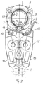
Figur 1- eine teilweise geschnittene Ansicht eines erfindungsgemässen Presswerkzeuges in geöffnetem Zustand,
Figur 2- eine Ansicht eines erfindungsgemässen Presswerkzeuges, das um ein zu verpressendes Rohrende gelegt ist,
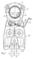
Figur 3- eine Ansicht eines erfindungsgemässen Presswerkzeuges, das um ein zu verpressendes Rohrende gelegt ist sowie ein Antrieb zum Schliessen des Presswerkzeuges,
Figur 4- eine Ansicht gemäss
Figur 2, jedoch mit geschlossenem Presswerkzeug und somit nach der Durchführung der Verpressung, Figur 5- eine Ansicht gemäss
Figur 3, jedoch nach dem Pressvorgang und Figur 6- ein Schnitt entlang der Linie VI-VI der
Figur 5.
- FIG. 1
- a partially sectioned view of an inventive pressing tool in the open state,
- FIG. 2
- a view of a novel pressing tool, which is placed around a pipe end to be pressed,
- FIG. 3
- a view of an inventive pressing tool, which is placed around a pipe end to be pressed and a drive for closing the pressing tool,
- FIG. 4
- a view according to Figure 2, but with a closed pressing tool and thus after the implementation of the compression,
- FIG. 5
- a view according to Figure 3, but after the pressing process and
- FIG. 6
- a section along the line VI-VI of Figure 5.
Das in Figur 1 gezeigte Presswerkzeug 1 ist eine sogenannte
Pressschlinge, die ein mittleres Pressbackenelement 2 sowie zwei
äussere Pressbackenelemente 3 und 4 aufweist. Das Pressbackenelement
2 ist mit zwei Scharniergelenken 5 mit den anderen
Pressbackenelementen 3 und 4 gelenkig verbunden. Am Pressbackenelement
3 ist ein Bügel 11 schwenkbar gelagert, mit dem das
Presswerkzeug 1 gemäss Figur 2 provisorisch geschlossen werden
kann. Zur Offenbarung wird hier auch auf die EP 1 036 608 A des
Anmelders verwiesen, in welcher insbesondere die Funktion dieses
Bügels 11 offenbart ist. The
Die Pressbackenelemente 2, 3 und 4 weisen jeweils eine Innenseite
20, 21 bzw. 22 auf, welche die Pressflächen bilden und die
bei geschlossenem Presswerkzeug im Querschnitt eine runde und
geschlossene Pressfläche bilden. Die Innenseiten 20, 21 und 22
können vorstehende Rippen aufweisen, die sich in Umfangsrichtung
erstrecken und die sich beim Pressvorgang in die Aussenseite des
zu verpressenden Gegenstandes eingraben. Durch entsprechende
plastische Verformung kann damit beispielsweise das in Figur 2
angedeutete Wasserrohr 14 mit einem Pressfitting 13 verbunden
werden.The
Das gezeigte Presswerkzeug 1 ist wie erwähnt insbesondere eine
Pressschlinge. Grundsätzlich kann eine solche Pressschlinge auch
mehr als drei Pressbackenelemente aufweisen. Das erfindungsgemässe
Presswerkzeug ist aber nicht auf eine Pressschlinge beschränkt,
sondern kann beispielsweise auch als Presszange ausgebildet
werden, welche lediglich zwei Pressbackenelemente aufweist
und von Hand oder motorisch geschlossen wird. Der zu verpressende
Gegenstand ist vorzugsweise ein Rohr 14 und insbesondere
ein Rohr der Sanitärtechnik, grundsätzlich können mit dem
erfindungsgemässen Presswerkzeug aber auch andere Gegenstände
verpresst werden.The
Ist das Presswerkzeug 1 gemäss Figur 1 um das Rohr 14 gelegt und
mit dem Bügel 11 provisorisch verbunden, so wird die in Figur 3
gezeigte Schliesszange 15 an Nocken 16 der Pressbackenelemente 3
und 4 angelegt und diese wird mit einem hier nicht gezeigten
hydraulischen Antrieb geschlossen, indem Rollen 17 zwischen zwei
Hebeln 13 der Schliesszange hineingeschoben werden. Die
Schliesszange 15 und der genannte hydraulische Antrieb sind handelsübliche
Geräte und dem Fachmann gut bekannt. Vor dem Pressvorgang
besteht zwischen einer Anschlagfläche 24 des Pressbackenelementes
4 und einer Anschlagfläche 25 des Pressbackenelementes
3 ein Öffnungsspalt 19. Dieser Öffnungsspalt 19 wird beim
Verpressen geschlossen, sodass schliesslich die Anschlagflächen
24 und 25 aneinander anliegen. Dieser Öffnungsspalt 19 ist
vor dem Verpressen und während des Pressvorganges von einem
Stützteil 8 überbrückt, der am freien Ende 6 des Pressbackenelementes
3 angeordnet ist. Dieser Stützteil 8 ist ein Teil des
Pressbackenelementes 3 und insbesondere an diesem angeformt.
Grundsätzlich könnte dieser Stützteil 8 auch auf andere Weise
mit dem Pressbackenelement 3 fest verbunden sein. Der Stützteil
8 ist gemäss Figur 6 U-förmig ausgebildet und weist zwei
parallel zueinander verlaufende Seitenwandung 10 und eine diese
brückenartig verbindende Wandung 26 auf. Diese Wandung 26 weist
vorspringende Rippen 18 auf, und ist in Umfangsrichtung entsprechend
der Innenseite 20 kreisförmig gebogen, wie die Figur 1 erkennen
lässt. Die Rippen 18 entsprechen Rippen 27 der Pressbackenelemente
2, 3 und 4 und bilden jeweils eine Fortsetzung von
diesen.Is the
Das Pressbackenelement 4 weist an seinem freien Ende 7 eine Ausnehmung
9 auf, die korrespondierend zum Stützteil 8 ausgebildet
ist und welche im geschlossenen Zustand dieses Stützteil 8 aufnimmt.
Ist das Presswerkzeug 1 gemäss Figur 3 an ein Rohr 14 angelegt,
jedoch noch nicht geschlossen, so greift der Stützteil 8
vorzugsweise geringfügig in die Ausnehmung 8 ein. Im Bereich des
Öffnungsspaltes 19 ist somit das zu verpressende Rohr 14 an seiner
Aussenseite vom Stützteil 8 gestützt und kann beim Verpressen
radial nicht ausweichen. Wird nun das Presswerkzeug 1 geschlossen,
so wird der Stützteil 8 in die Ausnehmung 9 hineingeschoben.
Die Wandung 26 gleitet hierbei an der Aussenseite 28
des zu verpressenden Rohres 14 entlang. Die Dicke der Wandung 26
ist vergleichsweise klein und beträgt beispielsweise 1 bis 3 mm. The
Ist das Presswerkzeug 1 gemäss den Figuren 4 und 5 geschlossen,
so ist das Rohr 14 zentrisch und rund verpresst und fest mit dem
Pressfitting 13 verbunden. Es ist somit keine Verpressung möglich,
bei welcher das Rohr 14 radial ausgebuchtet und sich ein
Wulst gebildet hat, der zwischen den Anschlagflächen 24 und 25
verpresst ist. Bei der Verwendung des erfindungsgemässen Presswerkzeuges
ist somit gewährleistet, dass der Querschnitt des
Rohres 14 kreisrund ist. Entsprechend ist die Innenseite 29 des
Rohres 14 im Querschnitt rund und eingelegte und hier nicht gezeigte
Dichtungsringe können optimal das Rohr 14 gegenüber dem
Pressfitting 13 abdichten. Das Rohr 14 ist insbesondere ein
plastisch verformbares Wasserrohr mit einer Kernschicht 14b aus
Aluminium und zwei mit dieser verbundenen Schichten 14a und 14c
aus Kunststoff.If the
Versuche haben nun überraschend gezeigt, dass bei der Verwendung
des erfindungsgemässen Presswerkzeuges 1 der Kraftaufwand beim
Verpressen wesentlich kleiner ist als bei einem vergleichsweisen
Presswerkzeug. Der Grund dürfte darin liegen, dass beim genannten
runden Verpressen weniger Energie für die plastische Verformung
im Bereich des Öffnungsspaltes 19 aufgewendet werden muss.
Eine exakte runde Verpressung ohne Ausbuchtungen ist offenbar
mit kleinerem Energie- bzw. Kraftaufwand möglich. Experiments have now surprisingly shown that in use
of the inventive
- 1.1.
- Presswerkzeugpress tool
- 2.Second
- PressbackenelementPress jaw element
- 3.Third
- PressbackenelementPress jaw element
- 4.4th
- PressbackenelementPress jaw element
- 5.5th
- Gelenkjoint
- 6.6th
- EndeThe End
- 7.7th
- EndeThe End
- 8.8th.
- Stützteilsupporting part
- 9.9th
- Ausnehmungrecess
- 10.10th
- SeitenwandSide wall
- 11.11th
- Bügelhanger
- 12.12th
- Leitungmanagement
- 13.13th
- PressfittingPress fitting
- 14.14th
- Rohrpipe
- 15.15th
- SchliesszangeSchliesszange
- 16.16th
- Nockencam
- 17.17th
- Rollenroll
- 18.18th
- Rippenribs
- 19.19th
- Öffnungsspaltopening gap
- 20.20th
- Innenseiteinside
- 21.21st
- Innenseiteinside
- 22.22nd
- Innenseiteinside
- 23.23rd
- Hebellever
- 24.24th
- Anschlagflächestop surface
- 25.25th
- Anschlagflächestop surface
- 26.26th
- Wandungwall
- 27.27th
- Rippenribs
- 28.28th
- Aussenseiteoutside
- 29.29th
- Innenseiteinside
Claims (4)
Priority Applications (3)
| Application Number | Priority Date | Filing Date | Title |
|---|---|---|---|
| AT03405848T ATE372840T1 (en) | 2003-11-27 | 2003-11-27 | PRESS TOOL |
| EP03405848A EP1535677B1 (en) | 2003-11-27 | 2003-11-27 | Press tool |
| DE50308188T DE50308188D1 (en) | 2003-11-27 | 2003-11-27 | press tool |
Applications Claiming Priority (1)
| Application Number | Priority Date | Filing Date | Title |
|---|---|---|---|
| EP03405848A EP1535677B1 (en) | 2003-11-27 | 2003-11-27 | Press tool |
Publications (2)
| Publication Number | Publication Date |
|---|---|
| EP1535677A1 true EP1535677A1 (en) | 2005-06-01 |
| EP1535677B1 EP1535677B1 (en) | 2007-09-12 |
Family
ID=34443148
Family Applications (1)
| Application Number | Title | Priority Date | Filing Date |
|---|---|---|---|
| EP03405848A Expired - Lifetime EP1535677B1 (en) | 2003-11-27 | 2003-11-27 | Press tool |
Country Status (3)
| Country | Link |
|---|---|
| EP (1) | EP1535677B1 (en) |
| AT (1) | ATE372840T1 (en) |
| DE (1) | DE50308188D1 (en) |
Cited By (4)
| Publication number | Priority date | Publication date | Assignee | Title |
|---|---|---|---|---|
| DE202009009456U1 (en) * | 2009-07-15 | 2010-11-25 | Novopress Gmbh Pressen Und Presswerkzeuge & Co. Kommanditgesellschaft | Pressing tool for connecting in particular tubular workpieces |
| EP2272629A1 (en) * | 2009-07-08 | 2011-01-12 | Novopress GmbH Pressen und Presswerkzeuge & Co. KG | Press tool and method for pressing in particular tubular workpieces |
| CN103889659A (en) * | 2011-08-19 | 2014-06-25 | 古斯塔夫.克劳克有限责任公司 | Pressing device |
| DE202013007496U1 (en) * | 2013-08-21 | 2014-11-28 | Novopress Gmbh Pressen Und Presswerkzeuge & Co. Kg | Pressing sling for connecting in particular tubular workpieces |
Families Citing this family (2)
| Publication number | Priority date | Publication date | Assignee | Title |
|---|---|---|---|---|
| EP3338908B1 (en) * | 2016-12-21 | 2019-11-20 | Von Arx AG | Press ring with elongated holes |
| DE202020102724U1 (en) * | 2020-05-14 | 2021-08-17 | Novopress Gmbh Pressen Und Presswerkzeuge & Co. Kommanditgesellschaft | Drive unit |
Citations (3)
| Publication number | Priority date | Publication date | Assignee | Title |
|---|---|---|---|---|
| US6044681A (en) * | 1997-03-11 | 2000-04-04 | Gustav Klauke Gmbh | Pressing tool |
| EP1036608A1 (en) * | 1999-03-17 | 2000-09-20 | Geberit Technik Ag | Latch on a press tool |
| EP1208949A2 (en) * | 2000-10-19 | 2002-05-29 | Gustav Klauke GmbH | Crimp pressing tool |
-
2003
- 2003-11-27 AT AT03405848T patent/ATE372840T1/en active
- 2003-11-27 DE DE50308188T patent/DE50308188D1/en not_active Expired - Lifetime
- 2003-11-27 EP EP03405848A patent/EP1535677B1/en not_active Expired - Lifetime
Patent Citations (3)
| Publication number | Priority date | Publication date | Assignee | Title |
|---|---|---|---|---|
| US6044681A (en) * | 1997-03-11 | 2000-04-04 | Gustav Klauke Gmbh | Pressing tool |
| EP1036608A1 (en) * | 1999-03-17 | 2000-09-20 | Geberit Technik Ag | Latch on a press tool |
| EP1208949A2 (en) * | 2000-10-19 | 2002-05-29 | Gustav Klauke GmbH | Crimp pressing tool |
Cited By (5)
| Publication number | Priority date | Publication date | Assignee | Title |
|---|---|---|---|---|
| EP2272629A1 (en) * | 2009-07-08 | 2011-01-12 | Novopress GmbH Pressen und Presswerkzeuge & Co. KG | Press tool and method for pressing in particular tubular workpieces |
| DE202009009456U1 (en) * | 2009-07-15 | 2010-11-25 | Novopress Gmbh Pressen Und Presswerkzeuge & Co. Kommanditgesellschaft | Pressing tool for connecting in particular tubular workpieces |
| CN103889659A (en) * | 2011-08-19 | 2014-06-25 | 古斯塔夫.克劳克有限责任公司 | Pressing device |
| CN103889659B (en) * | 2011-08-19 | 2016-06-01 | 古斯塔夫.克劳克有限责任公司 | Chain type pressing device, for the method for pressing workpiece and the subassembly of press member |
| DE202013007496U1 (en) * | 2013-08-21 | 2014-11-28 | Novopress Gmbh Pressen Und Presswerkzeuge & Co. Kg | Pressing sling for connecting in particular tubular workpieces |
Also Published As
| Publication number | Publication date |
|---|---|
| EP1535677B1 (en) | 2007-09-12 |
| ATE372840T1 (en) | 2007-09-15 |
| DE50308188D1 (en) | 2007-10-25 |
Similar Documents
| Publication | Publication Date | Title |
|---|---|---|
| DE102009032113B4 (en) | Pressing tool and method for pressing in particular tubular workpieces | |
| DE4240427C1 (en) | Press tool | |
| EP0671985A1 (en) | Pressing tool. | |
| DE2525313C2 (en) | Pipe socket | |
| DE1475131B1 (en) | Dowel designed as a spacer for lightweight panels | |
| DE2908935C2 (en) | Pipe connection with two parts pushed into one another | |
| DE3226868A1 (en) | PERMANENTLY TIGHT THREADED PIPE CONNECTION | |
| WO2002075199A1 (en) | Hose clamp and closing tool | |
| DE1652872B1 (en) | CONNECTION BETWEEN A CYLINDRICAL TUBE AND A CONNECTING PART PUSHED ON THIS | |
| DE102007051354A1 (en) | Flat metal band profile manufacturing method, involves bending region of flat metal band arranged adjacent to groove upward before and/or during engagement of rolls, which are engaged into bending region of bent upward region in metal band | |
| EP1535677B1 (en) | Press tool | |
| DE3328913A1 (en) | Device for fastening a pipe in a bore | |
| DE3718619C2 (en) | ||
| EP1793155B1 (en) | Pipe clamp, in particular tapping pipe clip | |
| DE202007007827U1 (en) | Clamp fitting for a pipe | |
| EP2791566B1 (en) | Method for producing a pipe connection by means of press fitting, and pressing tool | |
| DE19803536A1 (en) | Press tool | |
| DE3422040A1 (en) | Reverse forming process for the production of double-walled cylindrical workpieces and a forming tool for this purpose | |
| DE2332241B2 (en) | Pipe connection | |
| EP1649948B1 (en) | Pressing tool | |
| DE3617529C2 (en) | ||
| DE2513982B2 (en) | PIPE SEAL | |
| DE1806665B2 (en) | METHOD AND DEVICE FOR FASTENING METAL SLEEVES TO RIBBED REINFORCEMENT BARS AND BUTT JOINTS MADE BY THE METHOD | |
| DE102014112754A1 (en) | Upsetting process and compression device | |
| DE10202790A1 (en) | Pipe coupling Press |
Legal Events
| Date | Code | Title | Description |
|---|---|---|---|
| PUAI | Public reference made under article 153(3) epc to a published international application that has entered the european phase |
Free format text: ORIGINAL CODE: 0009012 |
|
| AK | Designated contracting states |
Kind code of ref document: A1 Designated state(s): AT BE BG CH CY CZ DE DK EE ES FI FR GB GR HU IE IT LI LU MC NL PT RO SE SI SK TR |
|
| AX | Request for extension of the european patent |
Extension state: AL LT LV MK |
|
| 17P | Request for examination filed |
Effective date: 20050614 |
|
| AKX | Designation fees paid |
Designated state(s): AT BE BG CH CY CZ DE DK EE ES FI FR GB GR HU IE IT LI LU MC NL PT RO SE SI SK TR |
|
| 17Q | First examination report despatched |
Effective date: 20061108 |
|
| GRAP | Despatch of communication of intention to grant a patent |
Free format text: ORIGINAL CODE: EPIDOSNIGR1 |
|
| GRAS | Grant fee paid |
Free format text: ORIGINAL CODE: EPIDOSNIGR3 |
|
| GRAA | (expected) grant |
Free format text: ORIGINAL CODE: 0009210 |
|
| AK | Designated contracting states |
Kind code of ref document: B1 Designated state(s): AT BE BG CH CY CZ DE DK EE ES FI FR GB GR HU IE IT LI LU MC NL PT RO SE SI SK TR |
|
| REG | Reference to a national code |
Ref country code: GB Ref legal event code: FG4D Free format text: NOT ENGLISH |
|
| REG | Reference to a national code |
Ref country code: CH Ref legal event code: EP Ref country code: CH Ref legal event code: NV Representative=s name: ISLER & PEDRAZZINI AG Ref country code: CH Ref legal event code: PCAR Free format text: ISLER & PEDRAZZINI AG;POSTFACH 1772;8027 ZUERICH (CH) |
|
| REF | Corresponds to: |
Ref document number: 50308188 Country of ref document: DE Date of ref document: 20071025 Kind code of ref document: P |
|
| REG | Reference to a national code |
Ref country code: IE Ref legal event code: FG4D Free format text: LANGUAGE OF EP DOCUMENT: GERMAN |
|
| PG25 | Lapsed in a contracting state [announced via postgrant information from national office to epo] |
Ref country code: FI Free format text: LAPSE BECAUSE OF FAILURE TO SUBMIT A TRANSLATION OF THE DESCRIPTION OR TO PAY THE FEE WITHIN THE PRESCRIBED TIME-LIMIT Effective date: 20070912 |
|
| NLV1 | Nl: lapsed or annulled due to failure to fulfill the requirements of art. 29p and 29m of the patents act | ||
| GBV | Gb: ep patent (uk) treated as always having been void in accordance with gb section 77(7)/1977 [no translation filed] | ||
| PG25 | Lapsed in a contracting state [announced via postgrant information from national office to epo] |
Ref country code: ES Free format text: LAPSE BECAUSE OF FAILURE TO SUBMIT A TRANSLATION OF THE DESCRIPTION OR TO PAY THE FEE WITHIN THE PRESCRIBED TIME-LIMIT Effective date: 20071223 Ref country code: NL Free format text: LAPSE BECAUSE OF FAILURE TO SUBMIT A TRANSLATION OF THE DESCRIPTION OR TO PAY THE FEE WITHIN THE PRESCRIBED TIME-LIMIT Effective date: 20070912 Ref country code: GR Free format text: LAPSE BECAUSE OF FAILURE TO SUBMIT A TRANSLATION OF THE DESCRIPTION OR TO PAY THE FEE WITHIN THE PRESCRIBED TIME-LIMIT Effective date: 20071213 |
|
| REG | Reference to a national code |
Ref country code: IE Ref legal event code: FD4D |
|
| PG25 | Lapsed in a contracting state [announced via postgrant information from national office to epo] |
Ref country code: GB Free format text: LAPSE BECAUSE OF FAILURE TO SUBMIT A TRANSLATION OF THE DESCRIPTION OR TO PAY THE FEE WITHIN THE PRESCRIBED TIME-LIMIT Effective date: 20070912 Ref country code: PT Free format text: LAPSE BECAUSE OF FAILURE TO SUBMIT A TRANSLATION OF THE DESCRIPTION OR TO PAY THE FEE WITHIN THE PRESCRIBED TIME-LIMIT Effective date: 20080212 Ref country code: SK Free format text: LAPSE BECAUSE OF FAILURE TO SUBMIT A TRANSLATION OF THE DESCRIPTION OR TO PAY THE FEE WITHIN THE PRESCRIBED TIME-LIMIT Effective date: 20070912 Ref country code: CZ Free format text: LAPSE BECAUSE OF FAILURE TO SUBMIT A TRANSLATION OF THE DESCRIPTION OR TO PAY THE FEE WITHIN THE PRESCRIBED TIME-LIMIT Effective date: 20070912 |
|
| BERE | Be: lapsed |
Owner name: GEBERIT TECHNIK A.G. Effective date: 20071130 |
|
| PG25 | Lapsed in a contracting state [announced via postgrant information from national office to epo] |
Ref country code: RO Free format text: LAPSE BECAUSE OF FAILURE TO SUBMIT A TRANSLATION OF THE DESCRIPTION OR TO PAY THE FEE WITHIN THE PRESCRIBED TIME-LIMIT Effective date: 20070912 Ref country code: SE Free format text: LAPSE BECAUSE OF FAILURE TO SUBMIT A TRANSLATION OF THE DESCRIPTION OR TO PAY THE FEE WITHIN THE PRESCRIBED TIME-LIMIT Effective date: 20071212 Ref country code: MC Free format text: LAPSE BECAUSE OF NON-PAYMENT OF DUE FEES Effective date: 20071130 |
|
| PLBE | No opposition filed within time limit |
Free format text: ORIGINAL CODE: 0009261 |
|
| STAA | Information on the status of an ep patent application or granted ep patent |
Free format text: STATUS: NO OPPOSITION FILED WITHIN TIME LIMIT |
|
| PG25 | Lapsed in a contracting state [announced via postgrant information from national office to epo] |
Ref country code: DK Free format text: LAPSE BECAUSE OF FAILURE TO SUBMIT A TRANSLATION OF THE DESCRIPTION OR TO PAY THE FEE WITHIN THE PRESCRIBED TIME-LIMIT Effective date: 20070912 |
|
| 26N | No opposition filed |
Effective date: 20080613 |
|
| PG25 | Lapsed in a contracting state [announced via postgrant information from national office to epo] |
Ref country code: BE Free format text: LAPSE BECAUSE OF NON-PAYMENT OF DUE FEES Effective date: 20071130 |
|
| PG25 | Lapsed in a contracting state [announced via postgrant information from national office to epo] |
Ref country code: IE Free format text: LAPSE BECAUSE OF FAILURE TO SUBMIT A TRANSLATION OF THE DESCRIPTION OR TO PAY THE FEE WITHIN THE PRESCRIBED TIME-LIMIT Effective date: 20070912 |
|
| PG25 | Lapsed in a contracting state [announced via postgrant information from national office to epo] |
Ref country code: EE Free format text: LAPSE BECAUSE OF FAILURE TO SUBMIT A TRANSLATION OF THE DESCRIPTION OR TO PAY THE FEE WITHIN THE PRESCRIBED TIME-LIMIT Effective date: 20070912 |
|
| PG25 | Lapsed in a contracting state [announced via postgrant information from national office to epo] |
Ref country code: FR Free format text: LAPSE BECAUSE OF NON-PAYMENT OF DUE FEES Effective date: 20071130 |
|
| PG25 | Lapsed in a contracting state [announced via postgrant information from national office to epo] |
Ref country code: SI Free format text: LAPSE BECAUSE OF FAILURE TO SUBMIT A TRANSLATION OF THE DESCRIPTION OR TO PAY THE FEE WITHIN THE PRESCRIBED TIME-LIMIT Effective date: 20070912 |
|
| PG25 | Lapsed in a contracting state [announced via postgrant information from national office to epo] |
Ref country code: CY Free format text: LAPSE BECAUSE OF FAILURE TO SUBMIT A TRANSLATION OF THE DESCRIPTION OR TO PAY THE FEE WITHIN THE PRESCRIBED TIME-LIMIT Effective date: 20070912 |
|
| PG25 | Lapsed in a contracting state [announced via postgrant information from national office to epo] |
Ref country code: BG Free format text: LAPSE BECAUSE OF FAILURE TO SUBMIT A TRANSLATION OF THE DESCRIPTION OR TO PAY THE FEE WITHIN THE PRESCRIBED TIME-LIMIT Effective date: 20071212 Ref country code: LU Free format text: LAPSE BECAUSE OF NON-PAYMENT OF DUE FEES Effective date: 20071127 |
|
| PG25 | Lapsed in a contracting state [announced via postgrant information from national office to epo] |
Ref country code: HU Free format text: LAPSE BECAUSE OF FAILURE TO SUBMIT A TRANSLATION OF THE DESCRIPTION OR TO PAY THE FEE WITHIN THE PRESCRIBED TIME-LIMIT Effective date: 20080313 Ref country code: TR Free format text: LAPSE BECAUSE OF FAILURE TO SUBMIT A TRANSLATION OF THE DESCRIPTION OR TO PAY THE FEE WITHIN THE PRESCRIBED TIME-LIMIT Effective date: 20070912 |
|
| REG | Reference to a national code |
Ref country code: CH Ref legal event code: PUE Owner name: GEBERIT INTERNATIONAL AG Free format text: GEBERIT TECHNIK AG#SCHACHENSTRASSE 77#8645 JONA (CH) -TRANSFER TO- GEBERIT INTERNATIONAL AG#SCHACHENSTRASSE 77#8645 JONA (CH) |
|
| PGFP | Annual fee paid to national office [announced via postgrant information from national office to epo] |
Ref country code: AT Payment date: 20101112 Year of fee payment: 8 |
|
| PGFP | Annual fee paid to national office [announced via postgrant information from national office to epo] |
Ref country code: IT Payment date: 20101127 Year of fee payment: 8 |
|
| PGFP | Annual fee paid to national office [announced via postgrant information from national office to epo] |
Ref country code: CH Payment date: 20111130 Year of fee payment: 9 |
|
| REG | Reference to a national code |
Ref country code: CH Ref legal event code: PL |
|
| REG | Reference to a national code |
Ref country code: AT Ref legal event code: MM01 Ref document number: 372840 Country of ref document: AT Kind code of ref document: T Effective date: 20121127 |
|
| PG25 | Lapsed in a contracting state [announced via postgrant information from national office to epo] |
Ref country code: CH Free format text: LAPSE BECAUSE OF NON-PAYMENT OF DUE FEES Effective date: 20121130 Ref country code: LI Free format text: LAPSE BECAUSE OF NON-PAYMENT OF DUE FEES Effective date: 20121130 Ref country code: AT Free format text: LAPSE BECAUSE OF NON-PAYMENT OF DUE FEES Effective date: 20121127 |
|
| PG25 | Lapsed in a contracting state [announced via postgrant information from national office to epo] |
Ref country code: IT Free format text: LAPSE BECAUSE OF NON-PAYMENT OF DUE FEES Effective date: 20121127 |
|
| REG | Reference to a national code |
Ref country code: DE Ref legal event code: R082 Ref document number: 50308188 Country of ref document: DE Representative=s name: HOEGER, STELLRECHT & PARTNER PATENTANWAELTE, DE Ref country code: DE Ref legal event code: R082 Ref document number: 50308188 Country of ref document: DE Representative=s name: HOEGER, STELLRECHT & PARTNER PATENTANWAELTE MB, DE |
|
| REG | Reference to a national code |
Ref country code: DE Ref legal event code: R082 Ref document number: 50308188 Country of ref document: DE Representative=s name: HOEGER, STELLRECHT & PARTNER PATENTANWAELTE MB, DE |
|
| PGFP | Annual fee paid to national office [announced via postgrant information from national office to epo] |
Ref country code: DE Payment date: 20151119 Year of fee payment: 13 |
|
| REG | Reference to a national code |
Ref country code: DE Ref legal event code: R119 Ref document number: 50308188 Country of ref document: DE |
|
| PG25 | Lapsed in a contracting state [announced via postgrant information from national office to epo] |
Ref country code: DE Free format text: LAPSE BECAUSE OF NON-PAYMENT OF DUE FEES Effective date: 20170601 |