EP1535534A2 - Device for manufacturing brushes and method applied thereby - Google Patents
Device for manufacturing brushes and method applied thereby Download PDFInfo
- Publication number
- EP1535534A2 EP1535534A2 EP04078053A EP04078053A EP1535534A2 EP 1535534 A2 EP1535534 A2 EP 1535534A2 EP 04078053 A EP04078053 A EP 04078053A EP 04078053 A EP04078053 A EP 04078053A EP 1535534 A2 EP1535534 A2 EP 1535534A2
- Authority
- EP
- European Patent Office
- Prior art keywords
- fibers
- mentioned
- bundle
- housing
- supply duct
- Prior art date
- Legal status (The legal status is an assumption and is not a legal conclusion. Google has not performed a legal analysis and makes no representation as to the accuracy of the status listed.)
- Granted
Links
- 238000004519 manufacturing process Methods 0.000 title claims abstract description 16
- 238000000034 method Methods 0.000 title claims description 10
- 239000000835 fiber Substances 0.000 claims abstract description 66
- 238000000227 grinding Methods 0.000 description 9
Images

Classifications
-
- A—HUMAN NECESSITIES
- A46—BRUSHWARE
- A46D—MANUFACTURE OF BRUSHES
- A46D3/00—Preparing, i.e. Manufacturing brush bodies
- A46D3/08—Parts of brush-making machines
- A46D3/082—Magazines for bristles; Feeding bristles to magazines; Knot picking
Definitions
- the present invention concerns a device for manufacturing brushes.
- this invention concerns a device for manufacturing brushes whereby bundles of fibers which are rounded at their far ends are provided in a brush body.
- This device makes it possible to manufacture brushes whereby the fibers are rounded after the fibers have been provided in the brush body.
- the present invention aims to provide a solution to the above-mentioned and other disadvantages.
- the invention concerns a device for manufacturing brushes, more particularly for inserting fibers in a brush body, which device mainly consists of a filling tool and at least one supply duct, whereby between the supply duct and the filling tool is provided at least one rounding means.
- An advantage of the device according to the invention is that the brushes can be manufactured practically entirely automatically in one and the same device, as a result of which the production cost can be restricted.
- This invention also aims a method for manufacturing a device as described above, whereby fibers are provided in at least one supply duct, which are presented to a filling tool which inserts the fibers in a brush body, and whereby the fibers are presented from each supply duct to a rounding means before being presented to the filling tool.
- the device 1 for manufacturing brushes 2 according to the invention mainly consists of supply ducts 3 for fibers 4, which are each provided with a bundle remover 5, which different bundle removers 5 are in this case placed around a distributing device 6, which distributing device 6 is mounted onto a filling tool 7 in the known manner.
- the supply ducts 3, five in total in this case, are preferably rectilinear and are provided with press-on means 8 on a first far end.
- each supply duct 3 consist of a housing 9, in the shape of a rigid body with a cylindrical opening 10, whereby in the casing of the housing 9 are each time provided two openings 11-12, the first opening 11 of which is provided opposite to the second far end of the above-mentioned supply ducts 3.
- openings 10 of the different bundle removers 5 is each time provided a rotatable cylindrical body 13 whose diameter is practically equal to the inner diameter of the openings 10.
- grooves 14 in the outer edge, five in this case, extending axially over the entire length of the bodies 13, whereby this length is in this case smaller than the length of the fibers 4 to be treated.
- Each of the cylindrical bodies 13 is provided with an independent drive which is not represented in the figures.
- the bundle removers 5 comprise a plate 15 situated opposite to one side of the cylindrical body 13 and which extends at least opposite to the entire outer edge of the cylindrical body 13 with a width which is equal to or larger than the depth of the grooves 14.
- Each of these plates 15 are preferably provided with means, not represented in the figures, which make it possible to axially move the plate 15 concerned in relation to the cylindrical body 13 concerned.
- each cylindrical body 13 is presented a rounding means 16, on a side opposite to the side of the above-mentioned plate 15, whereby each of these rounding means 16 is in this case formed of a grinding wheel 17 which is driven by a shaft 18 and which can be axially moved in relation to the cylindrical body 13 concerned.
- the bundle removers 5 each comprise a guide 19 which is presented to the same side of the cylindrical body 13 as the grinding wheel 17, but on a different place, namely at the height of the second opening 12 in the above-mentioned housing 9.
- These guides 19 are provided with an edge 20 which is oriented slantingly in relation to the radial direction of the above-mentioned cylindrical body 13.
- the distributing device 6, which is known from Belgian patent No 1,013,374, consists of a housing 21 with a cylindrical opening 22 which coincides, there where the bundle removers 5 abut the distributing device 6, with the housing 9 of said bundle removers 5.
- This housing 21 is provided with openings which coincide with the above-mentioned opening 12 of the different housings 9 of the above-mentioned bundle removers 5.
- the housing 21 is provided with an extra opening 23 on the spot where the distributing device 6 is erected against the filling tool 7.
- two cartridges 24-25 are provided in a coaxially rotatable manner in the opening 22, which is provided in the housing 21 of the distributing device 6.
- cartridges 24-25 are made in the shape of identical segments of a circle which are each provided with a drive, which is not represented in the figures.
- the filling tool 7, which is also known from BE 1,013,374, mainly consists of a base 28 which is connected to the housing 21 of the distributing device 6 at the height of the above-mentioned opening 23.
- a bundle remover 29 which can be moved to and fro and which is provided with a recess 30.
- the filling tool 7 comprises means 31 for inserting fibers 4 in a brush body 32 which is presented to the filling tool 7.
- the method for manufacturing brushes 2 which is applied when using this device is simple and as follows.
- fibers 4 which may differ as far as color, size, type and/or the like is concerned, are provided in the different supply ducts 3 of the device 1.
- the cylindrical body 13 of the bundle remover 5 concerned is rotated until a groove 14 is situated opposite to the above-mentioned first opening 11 in the corresponding housing 9, whereby the press-on means 8 push the fibers 4 through said opening 11 in the groove 14.
- the far ends of the fibers 4 are rounded by rotating the grinding wheel 17, and by bringing the fibers 4 into contact with the grinding wheel 17 by axially moving the plate 15 and/or the grinding wheel 17 in relation to the cylindrical body 13.
- the far ends of the fibers 4 are preferably, at first, moved only a little bit out of the cylindrical body 13, such that the far ends of these fibers 4 cannot be pushed far away from each other by the rotating grinding wheel 17.
- the fibers 4 can be pushed further out of the body 13, by axially moving the plate 15 towards the cylindrical body 13, and by moving the grinding wheel 17 away from the cylindrical body 13 practically proportionally, such that the distance between the plate 15 and the grinding wheel 17 remains practically the same, namely a little bit shorter than the length of the fibers 4.
- the fibers 4 are removed out of the bundle remover 5 by rotating the groove 14 concerned with rounded fibers along the above-mentioned guide 19, whereby the fibers 4, which now protrude partly out of the cylindrical body 13, are pushed against the slanting wall 20 of the guide, as represented in figures 6 to 8.
- the fibers 4 which are removed out of the grooves 14 of the bundle removers 5 are put in one of the recesses 26 of the cartridges 24-25, by presenting these recesses 26 in relation to the second opening 12 in the housing 9-21 of the bundle remover 5 concerned, from where the rounded fibers 4 are removed out of one of the grooves 14 at that time.
- This co-operation comprises the presentation of fibers 4 to the recess 30 in the bundle remover 29; presenting the bundle of fibers 4, in the above-mentioned recess 30, to the filling tool 7 which, in the known manner, inserts the bundle of fibers 4 in the brush body 32 which is also presented in front of the filling tool 7.
- Such an embodiment is especially useful when the fibers 4 are inserted as folded in two, whereby the far ends of the fibers 4 both extend outward.
- the present invention is by no means limited to the embodiment given as example and represented in the accompanying drawings; on the contrary, such a device and method can be made according to different variants while still remaining within the scope of the invention.
Landscapes
- Engineering & Computer Science (AREA)
- Manufacturing & Machinery (AREA)
- Brushes (AREA)
Abstract
Description
- The present invention concerns a device for manufacturing brushes.
- More particularly, this invention concerns a device for manufacturing brushes whereby bundles of fibers which are rounded at their far ends are provided in a brush body.
- From Belgian patent No. 1,013,374 in the name of FIRMA G.B. BOUCHERIE N.V., a device for manufacturing brushes is known, whereby fibers are supplied from different fiber loading spaces to a filling tool which inserts the fibers in a brush body on the one hand, and whereby the fibers in the fiber loading spaces are filled up from fiber supply ducts.
- This device makes it possible to manufacture brushes whereby the fibers are rounded after the fibers have been provided in the brush body.
- This is disadvantageous, however, in that when the different fibers in the brush body differ in length, or when fiber bundles are not cut off straight, it turns out to be extremely difficult to round the far ends of the shorter fibers in the brush body without damaging the longer fibers, such that one is limited in forming the fiber profile of the finished brushes.
- In order to remedy this disadvantage, a device for rounding the far ends of the fibers before they are provided in the above-mentioned fiber supply ducts is known.
- The disadvantage of the use of both separate devices is that the fibers are first cut at the desired length, must then be provided in the known device for rounding the fibers and must finally be transferred from this rounding device to the above-mentioned fiber supply ducts.
- The transport of the fibers between the device for rounding the fibers and the above-mentioned fiber supply ducts is done in a predominantly manual manner up to now, which is laborious and time-consuming, with as an additional disadvantage that a worker must stay on the spot all the time to continually fill up the device for manufacturing brushes from the above-mentioned device for rounding the far ends of fibers, as a result of which the labor costs form a relatively important part of the total production costs.
- The present invention aims to provide a solution to the above-mentioned and other disadvantages.
- To this end, the invention concerns a device for manufacturing brushes, more particularly for inserting fibers in a brush body, which device mainly consists of a filling tool and at least one supply duct, whereby between the supply duct and the filling tool is provided at least one rounding means.
- An advantage of the device according to the invention is that the brushes can be manufactured practically entirely automatically in one and the same device, as a result of which the production cost can be restricted.
- This invention also aims a method for manufacturing a device as described above, whereby fibers are provided in at least one supply duct, which are presented to a filling tool which inserts the fibers in a brush body, and whereby the fibers are presented from each supply duct to a rounding means before being presented to the filling tool.
- In order to better explain the characteristics of the invention, the following preferred embodiment of a device for manufacturing brushes and of a method applied thereby is described as an example only without being limitative in any way, with reference to the accompanying drawings, in which:
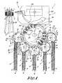
- figure 1 schematically represents a top view of a device according to the invention;
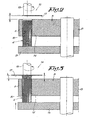
- figure 2 represents a section to a larger scale according to line II-II in figure 1;
- figures 3 and 4 represent the same part of the device as in figure 2, but according to two other positions;
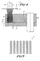
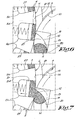
- figures 5 and 6 represent a part which is indicated in figure 1 by F5, F6 respectively, to a larger scale;
- figures 7 and 8 represent the same part as in figure 6, but for successive operational steps.
-
- As represented in figure 1, the device 1 for manufacturing brushes 2 according to the invention mainly consists of
supply ducts 3 forfibers 4, which are each provided with abundle remover 5, whichdifferent bundle removers 5 are in this case placed around a distributingdevice 6, which distributingdevice 6 is mounted onto afilling tool 7 in the known manner. - The
supply ducts 3, five in total in this case, are preferably rectilinear and are provided with press-on means 8 on a first far end. - The
bundle removers 5, on the far end of eachsupply duct 3, each consist of a housing 9, in the shape of a rigid body with acylindrical opening 10, whereby in the casing of the housing 9 are each time provided two openings 11-12, the first opening 11 of which is provided opposite to the second far end of the above-mentionedsupply ducts 3. - In the above-mentioned
openings 10 of thedifferent bundle removers 5 is each time provided a rotatablecylindrical body 13 whose diameter is practically equal to the inner diameter of theopenings 10. - In these
cylindrical bodies 13 are providedgrooves 14 in the outer edge, five in this case, extending axially over the entire length of thebodies 13, whereby this length is in this case smaller than the length of thefibers 4 to be treated. - Each of the
cylindrical bodies 13 is provided with an independent drive which is not represented in the figures. - As is represented in figures 2 to 4, the
bundle removers 5 comprise aplate 15 situated opposite to one side of thecylindrical body 13 and which extends at least opposite to the entire outer edge of thecylindrical body 13 with a width which is equal to or larger than the depth of thegrooves 14. - Each of these
plates 15 are preferably provided with means, not represented in the figures, which make it possible to axially move theplate 15 concerned in relation to thecylindrical body 13 concerned. - To each
cylindrical body 13 is presented arounding means 16, on a side opposite to the side of the above-mentionedplate 15, whereby each of theserounding means 16 is in this case formed of agrinding wheel 17 which is driven by ashaft 18 and which can be axially moved in relation to thecylindrical body 13 concerned. - As represented in figures 1 and 6 to 8, the
bundle removers 5 each comprise aguide 19 which is presented to the same side of thecylindrical body 13 as thegrinding wheel 17, but on a different place, namely at the height of thesecond opening 12 in the above-mentioned housing 9. - These
guides 19 are provided with anedge 20 which is oriented slantingly in relation to the radial direction of the above-mentionedcylindrical body 13. - The distributing
device 6, which is known from Belgian patent No 1,013,374, consists of ahousing 21 with acylindrical opening 22 which coincides, there where thebundle removers 5 abut the distributingdevice 6, with the housing 9 of saidbundle removers 5. - This
housing 21 is provided with openings which coincide with the above-mentionedopening 12 of the different housings 9 of the above-mentionedbundle removers 5. Thehousing 21 is provided with anextra opening 23 on the spot where the distributingdevice 6 is erected against thefilling tool 7. - According to the most preferred embodiment, two cartridges 24-25 are provided in a coaxially rotatable manner in the opening 22, which is provided in the
housing 21 of the distributingdevice 6. - These cartridges 24-25 are made in the shape of identical segments of a circle which are each provided with a drive, which is not represented in the figures.
- In the outer edge of the cartridges 24-25 are provided each time five
recesses 26 in this case, in which are provided press-on means 27 in the shape of pistons excited with springs. - The
filling tool 7, which is also known from BE 1,013,374, mainly consists of abase 28 which is connected to thehousing 21 of the distributingdevice 6 at the height of the above-mentionedopening 23. - In the above-mentioned
base 28 is provided, as is known, abundle remover 29 which can be moved to and fro and which is provided with arecess 30. - Further, the
filling tool 7 comprises means 31 for insertingfibers 4 in a brush body 32 which is presented to thefilling tool 7. - The method for manufacturing brushes 2 which is applied when using this device is simple and as follows.
- As is known,
fibers 4 which may differ as far as color, size, type and/or the like is concerned, are provided in thedifferent supply ducts 3 of the device 1. - These
fibers 4 are pushed to thedifferent bundle removers 5 at the far ends of thesupply ducts 3 by the press-on means 8. - In order to fill one of the
grooves 14 of one of thebundle removers 5 withfibers 4, thecylindrical body 13 of thebundle remover 5 concerned is rotated until agroove 14 is situated opposite to the above-mentionedfirst opening 11 in the corresponding housing 9, whereby the press-on means 8 push thefibers 4 through said opening 11 in thegroove 14. - Once the
groove 14 is filled, it can be presented to the rounding means 16 concerned by rotating thecylindrical body 13. - The far ends of the
fibers 4 are rounded by rotating thegrinding wheel 17, and by bringing thefibers 4 into contact with the grindingwheel 17 by axially moving theplate 15 and/or thegrinding wheel 17 in relation to thecylindrical body 13. - In order to round the
fibers 4, the far ends of thefibers 4 are preferably, at first, moved only a little bit out of thecylindrical body 13, such that the far ends of thesefibers 4 cannot be pushed far away from each other by the rotatinggrinding wheel 17. - Secondly, the
fibers 4 can be pushed further out of thebody 13, by axially moving theplate 15 towards thecylindrical body 13, and by moving thegrinding wheel 17 away from thecylindrical body 13 practically proportionally, such that the distance between theplate 15 and thegrinding wheel 17 remains practically the same, namely a little bit shorter than the length of thefibers 4. - When the far ends of the
fibers 4 are rounded in a shape such as represented, for example, in figure 5, thegrinding wheel 17 and theplate 15 are moved away from each other and thecylindrical body 13 rotates further in the direction of theguide 19 and thesecond opening 12 in the housing 9 of thebundle remover 5 concerned. - The
fibers 4 are removed out of thebundle remover 5 by rotating thegroove 14 concerned with rounded fibers along the above-mentionedguide 19, whereby thefibers 4, which now protrude partly out of thecylindrical body 13, are pushed against theslanting wall 20 of the guide, as represented in figures 6 to 8. - The
fibers 4 which are removed out of thegrooves 14 of thebundle removers 5 are put in one of therecesses 26 of the cartridges 24-25, by presenting theserecesses 26 in relation to thesecond opening 12 in the housing 9-21 of thebundle remover 5 concerned, from where therounded fibers 4 are removed out of one of thegrooves 14 at that time. - In this manner, the
different recesses 26 in one of the cartridges 24-25 are filled withrounded fibers 4, while the other cartridge 24-25 works in conjunction with thebundle remover 29 of thefilling tool 7 in the known manner at that time. - This co-operation comprises the presentation of
fibers 4 to therecess 30 in thebundle remover 29; presenting the bundle offibers 4, in the above-mentionedrecess 30, to thefilling tool 7 which, in the known manner, inserts the bundle offibers 4 in the brush body 32 which is also presented in front of thefilling tool 7. - It should be noted that it is always possible to make the above-mentioned
supply ducts 3 work in conjunction with a singlecommon bundle remover 5, while it is also always possible to provide asingle supply duct 3 and to make thissupply duct 3 co-operate withseveral bundle removers 5. - Naturally, it is also possible, in the described embodiment, to provide a
rounding means 16 in theplate 15, for example exactly opposite to the present rounding means 16, such that both far ends of thefibers 4 are rounded. - Such an embodiment is especially useful when the
fibers 4 are inserted as folded in two, whereby the far ends of thefibers 4 both extend outward.
The present invention is by no means limited to the embodiment given as example and represented in the accompanying drawings; on the contrary, such a device and method can be made according to different variants while still remaining within the scope of the invention.
Claims (12)
- Device for manufacturing brushes, more particularly for inserting fibers in a brush body, which device mainly consists of a filling tool and at least one supply duct, characterized in that between the supply duct (3) and the filling tool (7) is provided at least one rounding means (16).
- Device according to claim 1, characterized in that it is provided with several supply ducts (3) which are each provided with a rounding means (16).
- Device according to any one of claims 1 and 2, characterized in that the rounding means (16) are each situated opposite to a bundle remover (5) which consists of a housing (9) with an opening (10) in which has been provided a body (13) which moves in a fitting manner, which comprises grooves (14) in its outer edge for picking up fibers (4).
- Device according to claim 3, characterized in that the above-mentioned housing (9) comprises an opening (11) which is provided opposite to a far end of one of the supply ducts (3).
- Device according to any one of claims 3 and 4, characterized in that between the different bundle removers (5) and the above-mentioned filling tool (7) is provided a distributing device (6) with at least one cartridge (24-25) provided with at least one recess (26).
- Device according to claim 5, characterized in that the above-mentioned distributing device (6) comprises a housing (21) which forms a whole with the housing (9) of the above-mentioned bundle removers (5), whereby in this housing (9-21), opposite to each of the bundle removers (5), is provided an opening (12).
- Device according to claim 6, characterized in that opposite to each of the above-mentioned openings (12) in the housing (9-21) is provided a guide (19), whereby this guide (19) has an edge (20) which is oriented slantingly in relation to the direction of movement of the moving body (13) of the bundle remover (5) concerned.
- Method for manufacturing brushes, which can be applied according to any one of the preceding claims, whereby fibers are applied in at least one supply duct and are presented to a filling tool which inserts the fibers in a brush body, characterized in that the fibers (4) are presented from each supply duct (3) to a rounding means (16), before presenting them to the filling tool (7).
- Method according to claim 8, characterized in that the fibers (4) of each supply duct (3) are loaded in grooves (14) of a moving body (13), by moving the body (13), such that the groove (14) concerned is presented to the supply duct (3) concerned which is provided with press-on means (8) which push the fibers (4) in the groove (14).
- Method according to claim 9, characterized in that the fibers (4) which are loaded in the above-mentioned groove (14) are presented to the rounding means (16) by moving the cylindrical body (13).
- Method according to any one of claims 9 and 10, characterized in that the fibers (4) are loaded out of each of the above-mentioned grooves (14) in recesses (26), which are provided in cartridges (24-25) of a distributing device (6).
- Method according to claim 11, characterized in that the fibers (4) are removed out the above-mentioned groove (14) by means of a guide (19) which is provided with a slanting edge (20) in order to move the fibers (4) out of the groove (14) concerned in one of the recesses (26) in the above-mentioned cartridges (24-25) of the distributing device (6).
Applications Claiming Priority (2)
| Application Number | Priority Date | Filing Date | Title |
|---|---|---|---|
| BE200300634 | 2003-11-28 | ||
| BE2003/0634A BE1015733A3 (en) | 2003-11-28 | 2003-11-28 | Device for manufacturing brushes AND METHOD APPLIED THEREBY. |
Publications (3)
| Publication Number | Publication Date |
|---|---|
| EP1535534A2 true EP1535534A2 (en) | 2005-06-01 |
| EP1535534A3 EP1535534A3 (en) | 2007-03-28 |
| EP1535534B1 EP1535534B1 (en) | 2010-04-28 |
Family
ID=34437902
Family Applications (1)
| Application Number | Title | Priority Date | Filing Date |
|---|---|---|---|
| EP04078053A Expired - Lifetime EP1535534B1 (en) | 2003-11-28 | 2004-11-08 | Device for manufacturing brushes and method applied thereby |
Country Status (5)
| Country | Link |
|---|---|
| US (1) | US20050116528A1 (en) |
| EP (1) | EP1535534B1 (en) |
| BE (1) | BE1015733A3 (en) |
| DE (1) | DE602004026813D1 (en) |
| ES (1) | ES2344644T3 (en) |
Cited By (8)
| Publication number | Priority date | Publication date | Assignee | Title |
|---|---|---|---|---|
| WO2009049850A3 (en) * | 2007-10-15 | 2009-09-24 | G.B. Boucherie N.V. | Stuffing machine for brooms or brushes |
| EP1803372A3 (en) * | 2005-12-27 | 2010-03-03 | Firma G.B. Boucherie N.V. | Brush tamping machine |
| EP2243394A1 (en) * | 2009-04-21 | 2010-10-27 | M+C Schiffer GmbH | Method for creating a brush bundle and a device for carrying out the method |
| BE1018669A3 (en) * | 2008-04-14 | 2011-06-07 | Zahoransky Ag | MACHINE FOR MAKING BRUSHES. |
| CN104382336A (en) * | 2014-11-15 | 2015-03-04 | 陆光太 | Full-automatic brush making machine |
| EP3138438A1 (en) * | 2015-09-03 | 2017-03-08 | The Procter and Gamble Company | Tuft picker for a tuft picking device of a brush making machine |
| DE102020108452A1 (en) | 2020-03-26 | 2021-09-30 | Gb Boucherie Nv | Bristle processing device |
| WO2024223090A1 (en) * | 2023-04-28 | 2024-10-31 | Zahoransky Ag | Bundle segmenting device and method for segmenting bristle bundles, and bristle product manufacturing machine |
Families Citing this family (10)
| Publication number | Priority date | Publication date | Assignee | Title |
|---|---|---|---|---|
| DE10164336A1 (en) | 2001-12-28 | 2003-07-17 | Trisa Holding Ag Triengen | Toothbrush and method of making such a toothbrush |
| DE10259723A1 (en) | 2002-12-19 | 2004-07-01 | Trisa Holding Ag | Toothbrush and process for making it |
| BE1015591A3 (en) * | 2003-07-03 | 2005-06-07 | Boucherie Nv G B | |
| EP2526815B1 (en) * | 2008-06-07 | 2018-04-18 | Trisa Holding AG | Tooth brush with mixed bristle bundles and method for its manufacture |
| CN102123633B (en) * | 2008-08-20 | 2014-04-02 | 狮王株式会社 | Brush manufacturing method, toothbrush, and bristle bundling device |
| EP3138436A1 (en) | 2015-09-03 | 2017-03-08 | The Procter and Gamble Company | Tuft picking device for a brush making machine |
| MX2018012073A (en) | 2016-04-20 | 2019-05-22 | Trisa Holding Ag | PRODUCT TO BRUSH AND METHOD FOR YOUR PRODUCTION. |
| EP3351142B1 (en) | 2017-01-24 | 2019-10-16 | The Procter and Gamble Company | Tuft picker for a brush making machine |
| EP3351143B1 (en) | 2017-01-24 | 2019-11-06 | The Procter and Gamble Company | Tuft picker for a brush making machine |
| DE102022111906B3 (en) * | 2022-05-12 | 2023-06-15 | Zahoransky Ag | Device for compacting bristle bundles, brushware manufacturing machine and method for compacting bristle bundles |
Citations (1)
| Publication number | Priority date | Publication date | Assignee | Title |
|---|---|---|---|---|
| BE1013374A3 (en) | 2000-04-04 | 2001-12-04 | Boucherie Nv G B | METHOD AND APPARATUS FOR manufacturing brushes. |
Family Cites Families (5)
| Publication number | Priority date | Publication date | Assignee | Title |
|---|---|---|---|---|
| DE4040297C2 (en) * | 1990-12-17 | 2003-08-21 | Zahoransky Anton Gmbh & Co | Brush manufacturing machine |
| GB2287901B (en) * | 1994-03-29 | 1998-05-06 | Boucherie Nv G B | A brush making machine |
| BE1011547A3 (en) * | 1997-11-14 | 1999-10-05 | Boucherie Nv G B | APPARATUS FOR SUPPLYING FIBERS TO A FILLING MACHINE AT A BRUSH MANUFACTURING MACHINE. |
| US6523907B1 (en) * | 2000-02-01 | 2003-02-25 | Moll Industries, Inc. | Apparatus and method for producing brushware by injection molding |
| DE10030811C2 (en) * | 2000-06-23 | 2003-08-14 | Schiffer Fa M & C | Method and device for manufacturing brushes |
-
2003
- 2003-11-28 BE BE2003/0634A patent/BE1015733A3/en not_active IP Right Cessation
-
2004
- 2004-11-08 EP EP04078053A patent/EP1535534B1/en not_active Expired - Lifetime
- 2004-11-08 DE DE602004026813T patent/DE602004026813D1/en not_active Expired - Lifetime
- 2004-11-08 ES ES04078053T patent/ES2344644T3/en not_active Expired - Lifetime
- 2004-11-17 US US10/989,272 patent/US20050116528A1/en not_active Abandoned
Patent Citations (1)
| Publication number | Priority date | Publication date | Assignee | Title |
|---|---|---|---|---|
| BE1013374A3 (en) | 2000-04-04 | 2001-12-04 | Boucherie Nv G B | METHOD AND APPARATUS FOR manufacturing brushes. |
Cited By (13)
| Publication number | Priority date | Publication date | Assignee | Title |
|---|---|---|---|---|
| EP1803372A3 (en) * | 2005-12-27 | 2010-03-03 | Firma G.B. Boucherie N.V. | Brush tamping machine |
| US7866757B2 (en) | 2005-12-27 | 2011-01-11 | Firma G.B. Boucherie N.V. | Brush stuffing machine |
| WO2009049850A3 (en) * | 2007-10-15 | 2009-09-24 | G.B. Boucherie N.V. | Stuffing machine for brooms or brushes |
| BE1018669A3 (en) * | 2008-04-14 | 2011-06-07 | Zahoransky Ag | MACHINE FOR MAKING BRUSHES. |
| EP2243394A1 (en) * | 2009-04-21 | 2010-10-27 | M+C Schiffer GmbH | Method for creating a brush bundle and a device for carrying out the method |
| CN104382336B (en) * | 2014-11-15 | 2016-08-31 | 陆光太 | A kind of full-automatic brush-making machine |
| CN104382336A (en) * | 2014-11-15 | 2015-03-04 | 陆光太 | Full-automatic brush making machine |
| EP3138438A1 (en) * | 2015-09-03 | 2017-03-08 | The Procter and Gamble Company | Tuft picker for a tuft picking device of a brush making machine |
| WO2017040132A1 (en) * | 2015-09-03 | 2017-03-09 | The Procter & Gamble Company | Tuft picker for a tuft picking device of a brush making machine |
| DE102020108452A1 (en) | 2020-03-26 | 2021-09-30 | Gb Boucherie Nv | Bristle processing device |
| WO2021191032A1 (en) | 2020-03-26 | 2021-09-30 | Gb Boucherie Nv | Bristle processing device |
| TWI854114B (en) * | 2020-03-26 | 2024-09-01 | 比利時商Gb保捷利股份有限公司 | Brush processing equipment |
| WO2024223090A1 (en) * | 2023-04-28 | 2024-10-31 | Zahoransky Ag | Bundle segmenting device and method for segmenting bristle bundles, and bristle product manufacturing machine |
Also Published As
| Publication number | Publication date |
|---|---|
| ES2344644T3 (en) | 2010-09-02 |
| DE602004026813D1 (en) | 2010-06-10 |
| BE1015733A3 (en) | 2005-07-05 |
| EP1535534B1 (en) | 2010-04-28 |
| EP1535534A3 (en) | 2007-03-28 |
| US20050116528A1 (en) | 2005-06-02 |
Similar Documents
| Publication | Publication Date | Title |
|---|---|---|
| EP1535534B1 (en) | Device for manufacturing brushes and method applied thereby | |
| US7530157B2 (en) | Method of forming coils of a stator of a rotary electric machine | |
| KR102209191B1 (en) | Method and apparatus for manufacturing rotor or stator of electric machine | |
| EP1528658A1 (en) | Coil forming device and coil forming method | |
| US4445272A (en) | Method and apparatus for stacking rotor blanks on a shaft | |
| CN104068614A (en) | Machine for making brushes | |
| WO2013101704A1 (en) | Crimper system | |
| EP0916283A1 (en) | Device for supplying fibres to a filling instrument in a brush manufacturing machine | |
| US6905176B2 (en) | Method and device for manufacturing brushes | |
| KR20180098298A (en) | APPARATUS AND METHOD FOR INTRODUCING WAVE WINDING OF PRE-MANUFACTURED WAVE-WINDING MATS IN STEROID SHEET METAL PACKET GROUPS | |
| EP1901632B1 (en) | Method for manufacturing brushes | |
| US10398220B2 (en) | Tuft-picking device for a brush-making machine | |
| US6666524B2 (en) | End-rounding devices and methods for end-rounding | |
| EP1561395B1 (en) | Device for manufacturing brushes | |
| AU2020246968B2 (en) | Portable machine for connecting chain links and ammunition | |
| CN223323175U (en) | Device for compacting bristle bundles and bristle product manufacturing machine | |
| DE50102255D1 (en) | Rotary drive for a spinning rotor during its cleaning | |
| CN109338971A (en) | A kind of new-type snowplough | |
| EP1772641A1 (en) | Coupling and method for manufacturing the same | |
| US20020163276A1 (en) | Segmented lamination cores and an apparatus and method of making | |
| US4846531A (en) | Bristle filled sleeve and method of filling and using same | |
| CN110636777B (en) | Brush packing device | |
| CN115606933B (en) | Cleaning brush manufacturing equipment and process based on injection molding waste regeneration technology | |
| US5542749A (en) | Method and apparatus for gathering and forming a tuft of brush bristles | |
| CN214383177U (en) | Spacer sleeve pipe cutting machine based on bamboo raft forming |
Legal Events
| Date | Code | Title | Description |
|---|---|---|---|
| PUAI | Public reference made under article 153(3) epc to a published international application that has entered the european phase |
Free format text: ORIGINAL CODE: 0009012 |
|
| AK | Designated contracting states |
Kind code of ref document: A2 Designated state(s): AT BE BG CH CY CZ DE DK EE ES FI FR GB GR HU IE IS IT LI LU MC NL PL PT RO SE SI SK TR |
|
| AX | Request for extension of the european patent |
Extension state: AL HR LT LV MK YU |
|
| PUAL | Search report despatched |
Free format text: ORIGINAL CODE: 0009013 |
|
| AK | Designated contracting states |
Kind code of ref document: A3 Designated state(s): AT BE BG CH CY CZ DE DK EE ES FI FR GB GR HU IE IS IT LI LU MC NL PL PT RO SE SI SK TR |
|
| AX | Request for extension of the european patent |
Extension state: AL HR LT LV MK YU |
|
| 17P | Request for examination filed |
Effective date: 20070912 |
|
| 17Q | First examination report despatched |
Effective date: 20071024 |
|
| AKX | Designation fees paid |
Designated state(s): BE CH DE ES IE IT LI |
|
| GRAP | Despatch of communication of intention to grant a patent |
Free format text: ORIGINAL CODE: EPIDOSNIGR1 |
|
| GRAS | Grant fee paid |
Free format text: ORIGINAL CODE: EPIDOSNIGR3 |
|
| GRAA | (expected) grant |
Free format text: ORIGINAL CODE: 0009210 |
|
| AK | Designated contracting states |
Kind code of ref document: B1 Designated state(s): BE CH DE ES IE IT LI |
|
| REG | Reference to a national code |
Ref country code: CH Ref legal event code: EP |
|
| REG | Reference to a national code |
Ref country code: IE Ref legal event code: FG4D |
|
| REF | Corresponds to: |
Ref document number: 602004026813 Country of ref document: DE Date of ref document: 20100610 Kind code of ref document: P |
|
| REG | Reference to a national code |
Ref country code: CH Ref legal event code: NV Representative=s name: R. A. EGLI & CO. PATENTANWAELTE |
|
| REG | Reference to a national code |
Ref country code: ES Ref legal event code: FG2A Ref document number: 2344644 Country of ref document: ES Kind code of ref document: T3 |
|
| PLBE | No opposition filed within time limit |
Free format text: ORIGINAL CODE: 0009261 |
|
| STAA | Information on the status of an ep patent application or granted ep patent |
Free format text: STATUS: NO OPPOSITION FILED WITHIN TIME LIMIT |
|
| 26N | No opposition filed |
Effective date: 20110131 |
|
| PG25 | Lapsed in a contracting state [announced via postgrant information from national office to epo] |
Ref country code: IE Free format text: LAPSE BECAUSE OF NON-PAYMENT OF DUE FEES Effective date: 20101108 |
|
| PGFP | Annual fee paid to national office [announced via postgrant information from national office to epo] |
Ref country code: ES Payment date: 20111228 Year of fee payment: 8 |
|
| PGFP | Annual fee paid to national office [announced via postgrant information from national office to epo] |
Ref country code: IT Payment date: 20131107 Year of fee payment: 10 |
|
| REG | Reference to a national code |
Ref country code: ES Ref legal event code: FD2A Effective date: 20140410 |
|
| PG25 | Lapsed in a contracting state [announced via postgrant information from national office to epo] |
Ref country code: ES Free format text: LAPSE BECAUSE OF NON-PAYMENT OF DUE FEES Effective date: 20121109 |
|
| PG25 | Lapsed in a contracting state [announced via postgrant information from national office to epo] |
Ref country code: IT Free format text: LAPSE BECAUSE OF NON-PAYMENT OF DUE FEES Effective date: 20141108 |
|
| PGFP | Annual fee paid to national office [announced via postgrant information from national office to epo] |
Ref country code: FR Payment date: 20181011 Year of fee payment: 18 |
|
| REG | Reference to a national code |
Ref country code: BE Ref legal event code: MM Effective date: 20191130 |
|
| PG25 | Lapsed in a contracting state [announced via postgrant information from national office to epo] |
Ref country code: BE Free format text: LAPSE BECAUSE OF NON-PAYMENT OF DUE FEES Effective date: 20191130 |
|
| PGFP | Annual fee paid to national office [announced via postgrant information from national office to epo] |
Ref country code: CH Payment date: 20211119 Year of fee payment: 18 |
|
| REG | Reference to a national code |
Ref country code: CH Ref legal event code: PL |
|
| PG25 | Lapsed in a contracting state [announced via postgrant information from national office to epo] |
Ref country code: LI Free format text: LAPSE BECAUSE OF NON-PAYMENT OF DUE FEES Effective date: 20221130 Ref country code: CH Free format text: LAPSE BECAUSE OF NON-PAYMENT OF DUE FEES Effective date: 20221130 |
|
| PGFP | Annual fee paid to national office [announced via postgrant information from national office to epo] |
Ref country code: DE Payment date: 20231116 Year of fee payment: 20 |
|
| REG | Reference to a national code |
Ref country code: DE Ref legal event code: R071 Ref document number: 602004026813 Country of ref document: DE |