KR20180098298A - APPARATUS AND METHOD FOR INTRODUCING WAVE WINDING OF PRE-MANUFACTURED WAVE-WINDING MATS IN STEROID SHEET METAL PACKET GROUPS - Google Patents
APPARATUS AND METHOD FOR INTRODUCING WAVE WINDING OF PRE-MANUFACTURED WAVE-WINDING MATS IN STEROID SHEET METAL PACKET GROUPS Download PDFInfo
- Publication number
- KR20180098298A KR20180098298A KR1020187020162A KR20187020162A KR20180098298A KR 20180098298 A KR20180098298 A KR 20180098298A KR 1020187020162 A KR1020187020162 A KR 1020187020162A KR 20187020162 A KR20187020162 A KR 20187020162A KR 20180098298 A KR20180098298 A KR 20180098298A
- Authority
- KR
- South Korea
- Prior art keywords
- rotor
- stator body
- coils
- grooves
- stator
- Prior art date
- Legal status (The legal status is an assumption and is not a legal conclusion. Google has not performed a legal analysis and makes no representation as to the accuracy of the status listed.)
- Ceased
Links
Images
Classifications
-
- H—ELECTRICITY
- H02—GENERATION; CONVERSION OR DISTRIBUTION OF ELECTRIC POWER
- H02K—DYNAMO-ELECTRIC MACHINES
- H02K15/00—Processes or apparatus specially adapted for manufacturing, assembling, maintaining or repairing of dynamo-electric machines
- H02K15/06—Embedding prefabricated windings in the machines
- H02K15/062—Windings in slots; Salient pole windings
- H02K15/065—Windings consisting of complete sections, e.g. coils or waves
- H02K15/066—Windings consisting of complete sections, e.g. coils or waves inserted perpendicularly to the axis of the slots or inter-polar channels
-
- H—ELECTRICITY
- H02—GENERATION; CONVERSION OR DISTRIBUTION OF ELECTRIC POWER
- H02K—DYNAMO-ELECTRIC MACHINES
- H02K1/00—Details of the magnetic circuit
- H02K1/06—Details of the magnetic circuit characterised by the shape, form or construction
- H02K1/12—Stationary parts of the magnetic circuit
- H02K1/16—Stator cores with slots for windings
-
- H—ELECTRICITY
- H02—GENERATION; CONVERSION OR DISTRIBUTION OF ELECTRIC POWER
- H02K—DYNAMO-ELECTRIC MACHINES
- H02K1/00—Details of the magnetic circuit
- H02K1/06—Details of the magnetic circuit characterised by the shape, form or construction
- H02K1/22—Rotating parts of the magnetic circuit
- H02K1/26—Rotor cores with slots for windings
-
- H—ELECTRICITY
- H02—GENERATION; CONVERSION OR DISTRIBUTION OF ELECTRIC POWER
- H02K—DYNAMO-ELECTRIC MACHINES
- H02K15/00—Processes or apparatus specially adapted for manufacturing, assembling, maintaining or repairing of dynamo-electric machines
- H02K15/02—Processes or apparatus specially adapted for manufacturing, assembling, maintaining or repairing of dynamo-electric machines of stator or rotor bodies
- H02K15/021—Magnetic cores
-
- H—ELECTRICITY
- H02—GENERATION; CONVERSION OR DISTRIBUTION OF ELECTRIC POWER
- H02K—DYNAMO-ELECTRIC MACHINES
- H02K15/00—Processes or apparatus specially adapted for manufacturing, assembling, maintaining or repairing of dynamo-electric machines
- H02K15/04—Processes or apparatus specially adapted for manufacturing, assembling, maintaining or repairing of dynamo-electric machines of windings prior to their mounting into the machines
- H02K15/043—Processes or apparatus specially adapted for manufacturing, assembling, maintaining or repairing of dynamo-electric machines of windings prior to their mounting into the machines winding flat conductive wires or sheets
-
- H—ELECTRICITY
- H02—GENERATION; CONVERSION OR DISTRIBUTION OF ELECTRIC POWER
- H02K—DYNAMO-ELECTRIC MACHINES
- H02K3/00—Details of windings
- H02K3/04—Windings characterised by the conductor shape, form or construction, e.g. with bar conductors
- H02K3/12—Windings characterised by the conductor shape, form or construction, e.g. with bar conductors arranged in slots
Landscapes
- Engineering & Computer Science (AREA)
- Power Engineering (AREA)
- Manufacturing & Machinery (AREA)
- Manufacture Of Motors, Generators (AREA)
- Windings For Motors And Generators (AREA)
Abstract
와이어로 이루어진 웨이브 와인딩을 포함하는 와인딩 매트(2)를 로터- 또는 스테이터 바디(4)에 도입하기 위한 장치는 로터- 또는 스테이터 바디(4)를 수용 및 지지하기 위한 수용 장치(5)와 와인딩 매트(2)를 수용 장치(5)에 공급하는 공급 장치(1)를 포함한다. 수용 장치(5)는 도입 장치(50)를 더 포함하고, 상기 도입 장치는 와인딩 매트(2)의 코일들(2a)을 분리하여 상기 코일들을 그루우브(43)의 깊이 방향으로 로터- 또는 스테이터 바디(4)에 도입한다. An apparatus for introducing a winding mat (2) comprising a wave winding of wires into a rotor-or stator body (4) comprises a receiving device (5) for receiving and supporting a rotor- or stator body (4) (1) for feeding the container (2) to the receiving device (5). The receiving device 5 further includes an introducing device 50 which separates the coils 2a of the winding mat 2 and separates the coils into a rotor- Into the body (4).
Description
본 발명은 스테이터 시트 금속 패킷에 와이어 웨이브 와인딩을 포함하는 와인딩 매트를 도입하기 위한 장치 및 스테이터를 제조하기 위한 방법에 관한 것이다. The present invention relates to a device for introducing a winding mat comprising a wire wave winding to a stator sheet metal packet and a method for manufacturing the stator.
와이어 웨이브 와인딩들은 대개 하나 이상의 와이어로 구성되지만, 특히 전적으로, 특징적인 웨이브 형상을 갖는 플랫 와이어(flat wire) 또는 프로파일된 와이어(profiled wire)로만 구성되는 것은 아닌 와인딩이다. 와이어는 본 출원과 관련해서 전류의 전도를 위해 적합한 스트랜드 형의, 와인딩될 수 있는 제품, 특히 금속 또는 금속합금으로 이루어진 제품이다. 이러한 제품은 와인딩 블레이드(winding blade) 주위에 와이어를 교대로 와인딩함으로써, 즉 와이어를 밴딩함으로써 제조된다. 이러한 공정에 의해 와이어 매트 또는 와인딩 매트가 형성되고, 상기 와이어 매트 또는 와인딩 매트는 후속해서 로터- 또는 스테이터 바디에, 특히 로터- 또는 스테이터 시트 금속 패킷에 설치되어야 한다. 이 경우 규정된 개수의 코일이 로터- 또는 스테이터 바디에 있는 각각의 그루우브 내에 배치되어야 한다. 선행기술에 따르면 이는 거의 자동화될 수 없다. 반경방향으로 확장 가능한 도입 장치 주위에 와인딩 매트를 와인딩한 후에, 상기 장치를 로터- 또는 스테이터 바디의 링 내에 배치하고, 반경방향 확장에 의해 링형으로 배치된 와인딩 매트를 로터- 또는 스테이터 바디의 내측 그루우브 내로 가압하는 것은 공개되어 있다. 이를 위해, 확장은 균일하게 이루어지는 것이 보장되어야 하고, 이는 연결된 복수의 코일로 이루어진 와인딩 매트 내의 하나의 코일에 대한 반경방향 가압은 해당하는 코일의 편향 운동뿐만 아니라, 와인딩 매트 전체의 코일들의 이동을 야기할 수 있다는 사실에 기초한다. 설명된 방법은 높은 정밀성을 요구하고, 해당하는 도입 장치들은 기본적으로 와인딩 매트들의 각각의 길이에 대해 새롭게 구성되어야 한다. Wirewave windings are usually composed of more than one wire, but in particular windings that are not solely composed of flat wire or profiled wire having a distinctive wave shape. The wire is a product of a strand-like, windable product, especially a metal or metal alloy, suitable for the conduction of current in the context of the present application. These products are manufactured by alternately winding wires around a winding blade, i. E. By bending the wire. This process forms a wire mat or winding mat and the wire mat or winding mat must subsequently be installed in a rotor- or stator body, in particular a rotor- or stator sheet metal packet. In this case, the specified number of coils must be placed in each groove in the rotor or stator body. According to prior art this can hardly be automated. After winding the winding mat around a radially expandable introducing device, the device is placed in the ring of the rotor-or stator body, and the winding mat arranged in a ring shape by radial expansion is wound on the inner side of the rotor- Pressing into the Uv is open. To this end, it is to be ensured that the expansion is made uniform, because the radial pressurization of one coil in the winding mat comprising a plurality of coils connected causes not only the deflection movement of the corresponding coil but also the movement of the coils throughout the winding mat It is based on the fact that you can do it. The described method requires high precision and the corresponding introduction devices must basically be newly constructed for each length of the winding mat.
본 발명의 과제는, 그루우브에 와인딩 매트들의 도입을 와인딩 매트들의 길이와 무관하게 그리고 신뢰적으로 정밀하게 실시할 수 있는, 로터- 또는 스테이터 바디에 와이어 웨이브 와인딩을 포함하는 와인딩 매트를 도입하기 위한 장치 및 로터- 또는 스테이터를 제조하기 위한 상응하는 방법을 제공하는 것이다. It is an object of the present invention to provide a method for introducing a winding mat comprising a wire-to-wire winding to a rotor-or stator body, which enables the introduction of winding mats to the grooves to be carried out reliably and precisely, And a corresponding method for manufacturing a rotor and / or a stator.
상기 과제는, 로터- 또는 스테이터 바디에 와이어 웨이브 와인딩을 포함하는 와인딩 매트를 도입하기 위한, 청구항 제 1 항의 특징들을 포함하는 장치에 의해 그리고 로터 또는 스테이터를 제조하기 위한, 청구항 제 12 항의 특징들을 포함하는 방법에 의해 해결된다. 바람직한 실시예들은 각각의 독립 청구항에 제시된다. This object is achieved by an apparatus comprising the features of
로터- 또는 스테이터 바디에 와이어 웨이브 와인딩을 포함하는 와인딩 매트를 도입하기 위한 본 발명에 따른 장치는 고정 위치에서 로터- 또는 스테이터 바디를 수용 및 지지하기 위한 수용 장치와 와인딩 매트를 수용 장치에 공급하는 공급 장치를 포함한다. 수용 장치는 도입 장치를 더 포함하고, 상기 도입 장치는 와인딩 매트의 코일들 또는 코일 그룹들을 분리하도록 및 코일들 또는 코일 그룹들을 로터- 또는 스테이터 바디에 대해 그루우브 깊이 방향으로 로터- 또는 스테이터 바디의 그루우브에 그루우브씩 차례로 도입하도록 설계된다. 그루우브 깊이 방향은, 그루우브가 로터- 또는 스테이터 바디 내로 연장되는 방향이다. 이는 반경방향일 수 있지만, 또한 반경방향에 대해 일정한 각도로 배치된 그루우브들이 로터- 또는 스테이터 바디 내에 제공될 수도 있다. 이때 그루우브 깊이 방향은 반경방향에 대해 언급된 각도로 연장되는 방향을 의미한다. A device according to the invention for introducing a winding mat comprising a wire-wave winding to a rotor-or stator body comprises a receiving device for receiving and supporting a rotor-or stator body in a fixed position, and a feeding device Device. The receiving device further comprises an introducing device which is arranged to separate the coils or groups of coils of the winding mat and to cooperate with the coils or groups of coils in the direction of the depth of the grooves relative to the rotor- The grooves are designed to introduce grooves one by one. The grooved depth direction is the direction in which the grooves extend into the rotor-or stator body. This can be a radial direction, but also grooves arranged at an angle to the radial direction may be provided in the rotor-or stator body. At this time, the depth direction of the grooves means a direction extending at an angle referred to the radial direction.
본 발명에 따라 로터- 또는 스테이터 바디는 로터- 또는 스테이터 시트 금속 패킷으로서 형성될 수 있지만, 이는 반드시 필수적인 것은 아니다. 패킷화되지 않은 재료들로, 예를 들어 소결된 재료들로 이루어진 로터- 또는 스테이터 바디들이 이용될 수도 있다. In accordance with the present invention, the rotor-or stator body may be formed as a rotor-or stator sheet metal packet, but this is not essential. With non-packetized materials, for example rotor-or stator bodies of sintered materials may be used.
본 발명에 따른 방법에 따라 - 이는 특히 전술한 및 후속해서 설명되는 본 발명에 따른 장치를 이용해서- 다음과 같이 이루어질 수 있다:According to the method according to the invention this can be done as follows, in particular using the device according to the invention as described above and subsequently explained:
먼저, 내측면 또는 외측면에 리세스로서 형성된 그루우브를 포함하는 로터- 또는 스테이터 바디가 제공된다. 그루우브들은 필수적이지는 않지만 반경방향으로 연장되는 그루우브 깊이 방향과 그루우브 길이방향을 갖는다. 하기 단계들이 실시된다:First, a rotor-or stator body is provided that includes a groove formed as a recess on the inner or outer surface. The grooves have a grooved depth direction and a grooved longitudinal direction that are not necessarily but radially extended. The following steps are carried out:
- 그루우브가 마련된 로터- 또는 스테이터 바디의 측면으로 웨이브 와인딩 매트를 접근시키는 단계;Approaching the wave-winding mat to the side of the rotor-or stator body provided with the grooves;
- 이하에 의해 코일들을 연속해서 도입하는 단계.- continuously introducing the coils by:
a. 하나의 코일 또는 복수의 코일을 분리시키고, a. Separating one coil or a plurality of coils,
b. 후속해서 코일 또는 복수의 코일을 도입 장치에 의해 그루우브에 도입하고, b. Subsequently, the coils or the plurality of coils are introduced into the grooves by the introduction device,
c. 그루우브에 코일(들)의 도입 후에 로터- 또는 스테이터 바디와 도입 장치 간에 상대 회전시키고, c. Relative rotation between the rotor-or stator body and the introduction device after introduction of the coil (s) into the grooves,
d. 단계들 a, b, 및 c를 반복해서 실시. d. Repeat steps a, b, and c.
웨이브 와인딩 매트는 와이어로 형성되고, 상기 와이어는 바람직하게 플랫 와이어 또는 프로파일된 와이어이다.The wave-wound mat is formed from a wire, which is preferably a flat wire or a profiled wire.
코일들로 충전된 그루우브들은 최종적으로 커버 슬라이더로 폐쇄될 수 있고, 이를 위해 본 발명에 따른 장치는 커버 슬라이더 도입 장치를 포함하며, 상기 커버 슬라이더 도입 장치는 코일들로 충전된 그루우브를 커버 슬라이더로 그루우브의 축방향 또는 그루우브 길이방향으로 폐쇄하도록 설계된다. The grooves filled with the coils can be finally closed with the cover slider. To this end, the apparatus according to the invention comprises a cover slider introduction device, which covers the grooves filled with the coils, In the axial direction of the grooves or in the grooved longitudinal direction.
각 그루우브에 차례로 와인딩들의 연속적인 도입에 의해 공정은 높은 정밀성으로 실시될 수 있고, 그루우브에 제대로 맞지 않는 위험이 감소한다. 또한, 본 발명은 스테이터 시트 금속 패킷 내의 외측 및 내측에 있는 그루우브들에 대해 균일하게 작용하고, 도입될 와인딩 매트의 길이와 무관하다. By the successive introduction of the windings in turn in each groove, the process can be carried out with high precision and the risk of not fitting the grooves is reduced. The present invention also works uniformly on the outer and inner grooves in the stator sheet metal packet and is independent of the length of the winding mat to be introduced.
바람직하게, 수용 장치는 회전 가능하게 설계되므로, 상기 수용 장치가 로터- 또는 스테이터 바디를 회전 방향으로 로터- 또는 스테이터 바디의 길이방향 축을 중심으로 회전시킬 수 있는 것이 제공된다. 로터- 또는 스테이터 바디와 도입 장치 간에 상대 회전이 이루어지는 것이 물론 중요하다. 결과적으로 수용 장치는 고정되어 지지될 수도 있고, 도입 장치는 이에 대해 상대 회전 가능하게 지지될 수 있다. 로터- 또는 스테이터 바디의 회전을 위해 특히 서보 모터가 제공될 수 있다. Preferably, the receiving device is designed to be rotatable so that the receiving device can rotate the rotor-or stator body about the longitudinal axis of the rotor-or stator body in the rotational direction. It is of course also important that a relative rotation takes place between the rotor-or stator body and the introduction device. As a result, the receiving device may be fixedly supported and the introducing device may be supported rotatably relative thereto. A servo motor, in particular, may be provided for rotation of the rotor-or stator body.
도입 장치는 본 발명의 바람직한 실시예에 따라 분리 슬라이더를 포함하고, 상기 분리 슬라이더는 로터- 또는 스테이터 바디를 향해 전진 방향으로 전진될 수 있다. 전진 방향은 이 경우 그루우브 깊이 방향에 대해 특히 0°가 아닌 각도로 연장된다. 이로 인해 분리 슬라이더는 코일들의 도입 방향에 대해 항상 비스듬하게 작용하고, 이는 필링(peeling) 방식의 분리를 용이하게 한다. The introducing device comprises a separating slider according to a preferred embodiment of the invention, and the separating slider can be advanced in the advancing direction towards the rotor-or stator body. The advancing direction in this case extends at an angle other than 0 [deg.] With respect to the groove depth direction. As a result, the separating slider always acts obliquely with respect to the direction of introduction of the coils, which facilitates the separation of the peeling method.
또한, 도입 장치는 그루우브 깊이 슬라이더, 특히 반경방향 슬라이더를 포함할 수 있다. 상기 슬라이더는 그루우브 깊이 방향으로 로터- 또는 스테이터 바디에 전진할 수 있게 형성된다. 따라서 상기 슬라이더는 분리된 코일들을 그루우브 깊이 방향으로 전진 이동에 의해 로터- 또는 스테이터 바디의 그루우브 내로 이동시킬 수 있다. In addition, the introducing device may include a grooved depth slider, in particular a radial slider. The slider is formed to advance in the rotor-or stator body in the groove depth direction. Thus, the slider can move the separated coils into the grooves of the rotor-or stator body by forward movement in the groove depth direction.
개별 코일들 또는 코일 그룹들의 도입을 용이하게 하기 위해 특히, 도입 장치가 코일들로 충전될 로터- 또는 스테이터 바디의 그루우브의 측면 가장자리 위에 위치 설정될 수 있는 가이드 장치를 포함하는 것이 제공될 수 있다. To facilitate the introduction of individual coils or groups of coils, it may be provided in particular that the introduction device comprises a guide device which can be positioned on the side edges of the grooves of the rotor-or stator body to be filled with coils .
가이드 장치가 충전될 그루우브의 측면에 위치 설정될 2개의 가이드 박판을 포함하는 경우에, 특히 바람직하다. 상기 가이드 박판을 따라 충전될 그루우브 내로 코일들이 슬라이딩할 수 있다. 특히, 바람직하게는 스프링 강, 다른 금속 또는 플라스틱으로 이루어질 수 있는 가이드 박판들은 또한, 날카로운 에지를 갖는 그루우브 가장자리와 접촉 및 그에 따른 와인딩 매트의 개별 섹션들의 손상이 방지되도록 위치 설정될 수 있다. It is particularly preferable when the guide device includes two guide thin plates to be positioned on the side surface of the groove to be charged. The coils may slide into the grooves to be filled along the guide foil. In particular, the guide strips, which may preferably consist of spring steel, other metal or plastic, can also be positioned so that contact with the grooved edge with a sharp edge and consequent damage to the individual sections of the winding mat is prevented.
또한, 실시예에 따라 이에 대한 대안으로서 또는 추가로 도입 장치는 위치 설정 장치를 포함할 수 있다. 상기 위치 설정 장치는, 도입 장치를 로터- 또는 스테이터 바디의 충전될 그루우브 위에 위치 설정하도록 설계된다. 이로 인해 분리된 코일 또는 코일 그룹이 충전될 그루우브 바로 위에 위치하는 지점에 항상 도입 장치가 배치된다. 바람직하게는 위치 설정 장치는 추가 슬라이더일 수 있고, 상기 슬라이더는 충전되지 않을 그루우브 내로, 바람직하게 충전될 그루우브에 인접한, 충전 순서에서 추후에 충전될 그루우브 내로 삽입되고, 따라서 도입 장치를 로터- 또는 스테이터 바디에 대해서 위치 설정한다. 따라서 로터- 또는 스테이터 바디 내의 각각의 그루우브의 충전이 효율적으로 및 확실하게 실시될 수 있다. Further alternatively or additionally, the introducing device according to the embodiment may comprise a positioning device. The positioning device is designed to position the introduction device on the grooves of the rotor-or stator body to be filled. This ensures that the introducing device is always located at a point directly above the grooves where the coil or group of coils is to be charged. Preferably the positioning device may be an additional slider and the slider is inserted into the grooves not to be filled, preferably adjacent to the grooves to be filled, into grooves to be filled later in the filling sequence, - Position with respect to the stator body. Thus, the charging of each groove in the rotor-or stator body can be carried out efficiently and reliably.
본 발명은 계속해서 도 1 및 도 2를 참고로 설명된다. The present invention will now be described with reference to Figures 1 and 2.
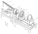
도 1은 본 발명에 따른 예시적인 장치를 도시한 사시도.
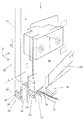
도 2는 도입 장치의 영역에서 로터- 또는 스테이터 바디를 도시한 도면.1 is a perspective view illustrating an exemplary apparatus in accordance with the present invention;
Figure 2 shows a rotor-or stator body in the region of the introduction device;
도 1에 도시된 장치에서 공급 장치(1)가 제공되고, 상기 공급 장치에 의해 와인딩 매트(이하 매트라고도 함; 2)가 로터- 또는 스테이터 바디(4)에 공급된다. 도시된 도면에 수용 장치(5)가 도시되고, 상기 수용 장치 위로 로터- 또는 스테이터 바디(4)가 수용되어(특히 여기에서 이송 장치(3)에 의해) 슬라이딩 되고, 수용 장치(5)에 고정될 수 있다. 수용 장치(5)에 고정 후에, 특히 링- 또는 디스크 형상의 로터- 또는 스테이터 바디는 기계축(A)을 중심으로 회전 방향(P1)으로 회전될 수 있다. 이는 바람직하게 상세히 도시되지 않은 회전 드라이브, 특히 서보 모터에 의해 이루어진다. A
수용 장치(5)에 도입 장치(50)가 배치되고, 상기 도입 장치는 이에 대해 별도로 배치될 수도 있다. 도시된 예에서 내부에 홈이 있는 로터- 또는 스테이터 바디(4)(여기에서 특히 스테이터 바디로 도시됨)가 도시되고, 장치 및 특히 본 발명에 따른 방법은 외부에 홈이 있는 로터- 또는 스테이터 바디로 실시될 수도 있다. 이러한 경우에 도입 장치(50)는 로터- 또는 스테이터 바디(4)의 내부 가장자리에 제공되는 것이 아니라(도시된 바와 같이), 상응하게 외부 가장자리에 제공될 수 있다. 방향 a은, 기계축(A)의 방향(X)에 대해 필수적이지는 않지만 바람직하게 평행하게 연장되는 그루우브들의 그루우브 길이 방향을 표시한다. The introducing
매트(2)의 코일들(2a)의 도입을 위한 도 2에 개략적으로 도시된 도입 과정은 따라서 내측에는 물론 외측에 그루우브(43)를 가진 로터- 또는 스테이터 바디(4)에 적용된다. 로터- 또는 스테이터 바디(4)의 그루우브들(43)은 그루우브 벽(41, 42) 사이에 형성된다. 인접한 2개의 벽(41, 42) 사이에서 그루우브(43)는 필수적인 것은 아니지만, 로터- 또는 스테이터 바디의 반경방향일 수 있는 그루우브 깊이 방향(R)으로 및 기계축의 방향(X)에 대해 바람직하게 평행하게 연장된 그루우브 길이 방향(a)으로 연장된다. 로터- 또는 스테이터 바디는 도시된 예에서 방향(P1)으로 기계축(A)을 중심으로 회전될 수 있다. The introduction process schematically illustrated in Fig. 2 for the introduction of the
도시된 예에서 매트(2)는 상하로 놓인 2개의 코일(2a)을 갖지만, 더 많거나 적은 코일(2a)도 가능할 수 있고, 특히 매트는 코일들의 하나의 층으로만 이루어질 수도 있다. 여기에서 도입 장치(50)를 이용한 코일들(2a)의 도입이 예시적으로 도시된다. 2개의 코일이 그루우브(43)에 도입되는 시점에 도입 과정이 도시된다. 화살표 방향(P1)으로 선행하는 그루우브(43')에 이미 코일들(2a)이 도입되어 있다. In the illustrated example, the mat 2 has two
도입 장치(50)는 먼저 분리 장치(53)에 의해 곧 도입될 코일 또는 코일 그룹(2a)을 매트(2)의 아직 도입되지 않은 나머지 코일들(2a)로부터 분리한다. 이를 위해 분리 장치는 바람직하게 로터- 또는 스테이터 바디의 방향으로 전달될 수 있게 형성되고, 이 경우 도시된 예에서 그루우브 깊이 방향(R)에 대해 일정한 각도로 연장되는 슬라이딩 방향(S)을 갖는 슬라이더(53)로서 형성된다. 로터- 또는 스테이터 바디에 방향(S)으로 슬라이더의 접근에 의해 아직 도입되지 않을 코일들(2a)은 제지될 수 있으므로, 상기 코일들은 충전될 그루우브(43) 위로 지나갈 수 없다. 이러한 시점에는 그루우브(43)에 도입될 코일들만이 그루우브 개구 위에 놓인다. 코일들이 그루우브(43)에 그루우브 깊이 방향(R)으로 도입될 수 있기 위해, 도입 장치(50)는 그루우브 깊이 방향(R)으로(도) 이동 가능한 부재, 특히 그루우브 깊이 슬라이더(52)를 포함하고, 상기 슬라이더는 분리 과정 후에 도입될 코일(2a)을 그루우브(43) 내로 가압한다. 이러한 과정은, 매트의 모든 코일들이 그루우브에 도입될 때까지, 반복된다. The introducing
도입을 용이하게 하기 위해 대안으로서 또는 보완적으로 2개의 수단이 제공될 수 있다. Two means may be provided, either alternatively or complementarily, to facilitate introduction.
한편으로는 분리된 코일들(2a)의 삽입은 가이드 부재(54, 55, 56)에 의해 간단해질 수 있다. 가이드 부재들은 일반적으로 가이드 박판(55, 56)이고, 상기 가이드 박판들은, 그루우브(43) 내로 슬라이딩 시 날카로운 에지를 갖는 가장자리(41, 42)에서 코일들(2a)이 손상되지 않도록 하기 위해, 그루우브 가장자리의 영역에 배치된다. 바람직하게 그루우브 깊이 방향으로 전달될 수 있는 가이드 박판(56)이 제공되고, 또한 비스듬하게 또는 휘어져 연장되는 다른 가이드 박판(55)이 제공되고, 상기 가이드 박판은 도입 장치(50)에 배치된 쐐기 부재(54)에 지지되므로, 일종의 호퍼(hopper) 공급이 이루어지고, 이러한 공급 시 코일은 박판(55) 위에서 슬라이딩하여 박판(56)에 제대로 맞고, 따라서 코일(2a)은 충전될 그루우브(43) 내로 정확히 안내되고, 거기에서 상기 코일은 후속해서 부재(52)에 의해 그루우브(43) 내로 가압될 수 있다. On the one hand, the insertion of the separated
제안된 제 2 수단으로서 위치 설정 장치(51)가 제공될 수 있다. 상기 장치의 목적은, 도입 장치(50), 특히 부재(52)를 충전될 그루우브(43) 위에 정확히 위치 설정하는 것이다. 이는 예를 들어, 위치 설정 장치(51)가 도입 장치(50)에 배치된 다른 그루우브 깊이 슬라이더로서 제공됨으로써 이루어질 수 있고, 상기 슬라이더는 분리 과정 및 그루우브(43)에 코일(2a)의 도입이 이루어지기 전에, 충전될 하나의 그루우브, 바람직하게 선행하는 그루우브(43')에 결합하고 따라서 도입 장치의 규정된 위치를 보장한다. A
전술한 장치 및 전술한 방법은, 로터- 또는 스테이터 바디(4)에 와인딩 매트(2)의 도입을 간단하게 하고 자동화할 수 있다. The above-described apparatus and the above-described method can simplify and automate the introduction of the winding mat 2 into the rotor-or stator body 4.
Claims (14)
- 내측면 및 외측면에 리세스로서 형성되고 그루우브 깊이 방향(R)과 그루우브 길이 방향(X)을 갖는 그루우브(43,, 43')를 포함하는 로터- 또는 스테이터 바디(4)를 제공하는 단계;
- 그루우브들(43)이 마련된 상기 로터- 또는 스테이터 바디(4)의 측면을 향해 웨이브 와인딩 매트(2)를 접근시키는 단계; 및
- 코일들을 연속해서 도입하는 단계로서,
a. 하나의 코일(2a) 또는 복수의 코일(2a)을 분리시키고,
b. 후속해서 상기 코일(2a) 또는 복수의 코일(2a)을 도입 장치(5)에 의해 그루우브(43)에 도입하고,
c. 그루우브(43)에 코일(들)의 도입 후에 상기 로터- 또는 스테이터 바디(4)와 상기 도입 장치(5) 간에 상대 회전시키고,
d. 단계들 a, b, 및 c를 반복해서 실시함으로써,
코일들을 연속해서 도입하는 단계
를 포함하는 것인 방법.By introducing the coils (2a) of the wave-winding mat (2) into the grooves (43) of the rotor-or stator body (4) using the apparatus according to one of claims 1 to 11, Lt; RTI ID = 0.0 >
A rotor or stator body 4 comprising grooves 43, 43 'formed as recesses on the inner and outer sides and having a grooved depth direction R and a grooved longitudinal direction X, ;
- approaching the wave-winding mat (2) towards the side of the rotor-or stator body (4) provided with grooves (43); And
- continuously introducing the coils,
a. One coil 2a or a plurality of coils 2a is separated,
b. Subsequently, the coil 2a or a plurality of coils 2a are introduced into the grooves 43 by the introduction device 5,
c. Relative to the rotor-or stator body 4 and the introduction device 5 after the introduction of the coil (s) into the grooves 43,
d. By repeating the steps a, b, and c,
The step of introducing the coils in succession
≪ / RTI >
Applications Claiming Priority (3)
| Application Number | Priority Date | Filing Date | Title |
|---|---|---|---|
| EP15201154.0A EP3182569B1 (en) | 2015-12-18 | 2015-12-18 | Device and method for inserting a wave winding from a prefabricated wave winding mat into slots of a stacked stator core |
| EP15201154.0 | 2015-12-18 | ||
| PCT/EP2016/081110 WO2017102904A1 (en) | 2015-12-18 | 2016-12-15 | Mechanism and method for introducing a wave winding from a prefabricated wave winding mat into stator sheet metal packet grooves |
Publications (1)
| Publication Number | Publication Date |
|---|---|
| KR20180098298A true KR20180098298A (en) | 2018-09-03 |
Family
ID=54850407
Family Applications (1)
| Application Number | Title | Priority Date | Filing Date |
|---|---|---|---|
| KR1020187020162A Ceased KR20180098298A (en) | 2015-12-18 | 2016-12-15 | APPARATUS AND METHOD FOR INTRODUCING WAVE WINDING OF PRE-MANUFACTURED WAVE-WINDING MATS IN STEROID SHEET METAL PACKET GROUPS |
Country Status (17)
| Country | Link |
|---|---|
| US (1) | US20180294702A1 (en) |
| EP (1) | EP3182569B1 (en) |
| JP (1) | JP2018537946A (en) |
| KR (1) | KR20180098298A (en) |
| CN (1) | CN108352769A (en) |
| BR (1) | BR112018007746A2 (en) |
| CA (1) | CA3001944A1 (en) |
| ES (1) | ES2841073T3 (en) |
| HR (1) | HRP20202037T1 (en) |
| HU (1) | HUE051907T2 (en) |
| MX (1) | MX2018007334A (en) |
| PL (1) | PL3182569T3 (en) |
| RU (1) | RU2018126314A (en) |
| SG (1) | SG11201803283PA (en) |
| SI (1) | SI3182569T1 (en) |
| WO (1) | WO2017102904A1 (en) |
| ZA (1) | ZA201801858B (en) |
Families Citing this family (6)
| Publication number | Priority date | Publication date | Assignee | Title |
|---|---|---|---|---|
| ES2806389T3 (en) * | 2018-03-20 | 2021-02-17 | Aumann Espelkamp Gmbh | Method and device for the introduction of a corrugated winding mat into the rotor or stator of an electrical machine, in particular into a pack of stator plates |
| NO20200543A1 (en) * | 2020-05-08 | 2021-07-19 | Alva Ind As | Method and apparatus for production of a multiphase electromagnetic mat for forming current carrying components of a power conversion system |
| CN113726110B (en) * | 2021-08-04 | 2022-09-23 | 中变智能装备(山东)有限公司 | Motor stator winding transfer equipment after moulding plastics |
| CN114830863B (en) * | 2022-04-25 | 2023-09-08 | 中建三局集团有限公司 | Quick restoration method for saline-alkali soil replacement |
| DE102022129444A1 (en) * | 2022-11-08 | 2024-05-08 | Schaeffler Technologies AG & Co. KG | Method for assembling a stator with a wave winding |
| DE102023122250A1 (en) * | 2023-08-21 | 2025-02-27 | Emil Motors GmbH | Method for producing a winding for a stator of an axial flux machine |
Family Cites Families (6)
| Publication number | Priority date | Publication date | Assignee | Title |
|---|---|---|---|---|
| JP3982446B2 (en) * | 2003-04-16 | 2007-09-26 | 株式会社日立製作所 | Manufacturing method of rotating electrical machine |
| DE10328956A1 (en) * | 2003-06-27 | 2005-01-20 | Elmotec Statomat Vertriebs Gmbh | Method and device for introducing wave windings in rotor and stator lamination packages of electrical machines |
| US7631413B2 (en) * | 2005-04-08 | 2009-12-15 | Bison Gear & Engineering Corporation | Method of manufacturing of an armature winding for electro-mechanical machines |
| FR2896351B1 (en) * | 2006-01-16 | 2008-04-18 | Valeo Equip Electr Moteur | METHOD FOR PRODUCING A STATOR OF ROTATING ELECTRIC MACHINE AND ARRANGEMENT OF CONDUCTORS ON A SUPPORT |
| US9071116B2 (en) * | 2013-01-17 | 2015-06-30 | Remy Technologies, Llc | Apparatus for installing stator winding conductors |
| JP6206588B2 (en) * | 2014-06-05 | 2017-10-04 | アイシン・エィ・ダブリュ株式会社 | Stator assembly method and stator assembly apparatus |
-
2015
- 2015-12-18 EP EP15201154.0A patent/EP3182569B1/en active Active
- 2015-12-18 PL PL15201154T patent/PL3182569T3/en unknown
- 2015-12-18 HU HUE15201154A patent/HUE051907T2/en unknown
- 2015-12-18 SI SI201531462T patent/SI3182569T1/en unknown
- 2015-12-18 ES ES15201154T patent/ES2841073T3/en active Active
-
2016
- 2016-12-15 CA CA3001944A patent/CA3001944A1/en not_active Abandoned
- 2016-12-15 CN CN201680067432.1A patent/CN108352769A/en active Pending
- 2016-12-15 JP JP2018531473A patent/JP2018537946A/en active Pending
- 2016-12-15 US US15/766,463 patent/US20180294702A1/en not_active Abandoned
- 2016-12-15 WO PCT/EP2016/081110 patent/WO2017102904A1/en not_active Ceased
- 2016-12-15 SG SG11201803283PA patent/SG11201803283PA/en unknown
- 2016-12-15 MX MX2018007334A patent/MX2018007334A/en unknown
- 2016-12-15 KR KR1020187020162A patent/KR20180098298A/en not_active Ceased
- 2016-12-15 RU RU2018126314A patent/RU2018126314A/en not_active Application Discontinuation
- 2016-12-15 BR BR112018007746-1A patent/BR112018007746A2/en not_active Application Discontinuation
-
2018
- 2018-03-20 ZA ZA2018/01858A patent/ZA201801858B/en unknown
-
2020
- 2020-12-21 HR HRP20202037TT patent/HRP20202037T1/en unknown
Also Published As
| Publication number | Publication date |
|---|---|
| RU2018126314A (en) | 2020-01-20 |
| SI3182569T1 (en) | 2021-07-30 |
| EP3182569B1 (en) | 2020-12-02 |
| SG11201803283PA (en) | 2018-05-30 |
| CN108352769A (en) | 2018-07-31 |
| PL3182569T3 (en) | 2021-03-08 |
| ZA201801858B (en) | 2018-12-19 |
| HUE051907T2 (en) | 2021-04-28 |
| CA3001944A1 (en) | 2017-06-22 |
| MX2018007334A (en) | 2018-08-24 |
| ES2841073T3 (en) | 2021-07-07 |
| WO2017102904A1 (en) | 2017-06-22 |
| HRP20202037T1 (en) | 2021-02-19 |
| US20180294702A1 (en) | 2018-10-11 |
| BR112018007746A2 (en) | 2018-10-23 |
| JP2018537946A (en) | 2018-12-20 |
| EP3182569A1 (en) | 2017-06-21 |
Similar Documents
| Publication | Publication Date | Title |
|---|---|---|
| KR20180098298A (en) | APPARATUS AND METHOD FOR INTRODUCING WAVE WINDING OF PRE-MANUFACTURED WAVE-WINDING MATS IN STEROID SHEET METAL PACKET GROUPS | |
| CN109075672B (en) | Method and apparatus for producing a rotor or stator for an electric machine | |
| US11581789B2 (en) | Method and device for winding a wave winding mat and wave winding mat that can be produced by means of the same | |
| US8661868B2 (en) | Apparatus for twisting electrical bar conductors, in particular for bar windings of electrical machines, with conductor's clamping system | |
| EP2591538B1 (en) | Method and apparatus for twisting bar conductors, in particular for bar windings of electric machines | |
| US10396639B2 (en) | Method for producing a winding of an electric machine | |
| CN111201700B (en) | Method for producing semi-finished products for stators and device for producing semi-finished products for stators | |
| US8786158B2 (en) | Continuously formed annular laminated article and method for its manufacture | |
| CN112703665B (en) | Method for providing hairpin elements for windings of an electric machine | |
| US10396638B2 (en) | Stator manufacturing apparatus and stator manufacturing method | |
| US20160156240A1 (en) | Stator winding for rotary electric machine, stator for rotary electric machine, method of manufacturing stator for rotary electric machine, and jig used in manufacturing stator for rotary electric machine | |
| CN102067418A (en) | Method for manufacturing stator coil | |
| US20170229936A1 (en) | Wire assembly for rotary electric machine and corresponding method to obtain the wire assembly | |
| JP5348506B2 (en) | Stator coil manufacturing method, motor using the stator coil, and stator coil manufacturing apparatus | |
| CN111434014A (en) | Method and device for the automated production of stators of electrical machines | |
| US20110167622A1 (en) | Method and apparatus for loading stator windings into a stator core | |
| EP3661017B1 (en) | Method for providing the winding of a plurality of wires within a stator pack of a stator for electric motors and processing line for the provision of the method | |
| JP2024523954A5 (en) | ||
| US6578255B2 (en) | Apparatus for laminating segmented core for electric machine | |
| EP3223411B1 (en) | Machine for performing wire windings on cores arranged on the internal lateral surface of cylindrical stators for electric motors | |
| EP4451527B1 (en) | System and method for inserting i-pins into a stator or rotor winding assembly | |
| JP5453854B2 (en) | Coil forming insertion device | |
| JP4705946B2 (en) | Stator manufacturing equipment | |
| KR20160017970A (en) | Forming tool for forming a wire of a stator winding for a rotary electric machine |
Legal Events
| Date | Code | Title | Description |
|---|---|---|---|
| PA0105 | International application |
Patent event date: 20180713 Patent event code: PA01051R01D Comment text: International Patent Application |
|
| PG1501 | Laying open of application | ||
| A201 | Request for examination | ||
| PA0201 | Request for examination |
Patent event code: PA02012R01D Patent event date: 20181001 Comment text: Request for Examination of Application |
|
| E902 | Notification of reason for refusal | ||
| PE0902 | Notice of grounds for rejection |
Comment text: Notification of reason for refusal Patent event date: 20191211 Patent event code: PE09021S01D |
|
| E601 | Decision to refuse application | ||
| PE0601 | Decision on rejection of patent |
Patent event date: 20200316 Comment text: Decision to Refuse Application Patent event code: PE06012S01D Patent event date: 20191211 Comment text: Notification of reason for refusal Patent event code: PE06011S01I |