EP1534912B1 - Tauchschwimmbeckenreiniger mit integraler wiederaufladbarer batterie - Google Patents
Tauchschwimmbeckenreiniger mit integraler wiederaufladbarer batterie Download PDFInfo
- Publication number
- EP1534912B1 EP1534912B1 EP03785234A EP03785234A EP1534912B1 EP 1534912 B1 EP1534912 B1 EP 1534912B1 EP 03785234 A EP03785234 A EP 03785234A EP 03785234 A EP03785234 A EP 03785234A EP 1534912 B1 EP1534912 B1 EP 1534912B1
- Authority
- EP
- European Patent Office
- Prior art keywords
- pool cleaner
- battery
- pool
- switch
- housing
- Prior art date
- Legal status (The legal status is an assumption and is not a legal conclusion. Google has not performed a legal analysis and makes no representation as to the accuracy of the status listed.)
- Expired - Lifetime
Links
Images



Classifications
-
- E—FIXED CONSTRUCTIONS
- E04—BUILDING
- E04H—BUILDINGS OR LIKE STRUCTURES FOR PARTICULAR PURPOSES; SWIMMING OR SPLASH BATHS OR POOLS; MASTS; FENCING; TENTS OR CANOPIES, IN GENERAL
- E04H4/00—Swimming or splash baths or pools
- E04H4/14—Parts, details or accessories not otherwise provided for
- E04H4/16—Parts, details or accessories not otherwise provided for specially adapted for cleaning
- E04H4/1654—Self-propelled cleaners
-
- Y—GENERAL TAGGING OF NEW TECHNOLOGICAL DEVELOPMENTS; GENERAL TAGGING OF CROSS-SECTIONAL TECHNOLOGIES SPANNING OVER SEVERAL SECTIONS OF THE IPC; TECHNICAL SUBJECTS COVERED BY FORMER USPC CROSS-REFERENCE ART COLLECTIONS [XRACs] AND DIGESTS
- Y10—TECHNICAL SUBJECTS COVERED BY FORMER USPC
- Y10T—TECHNICAL SUBJECTS COVERED BY FORMER US CLASSIFICATION
- Y10T29/00—Metal working
- Y10T29/49—Method of mechanical manufacture
- Y10T29/49002—Electrical device making
- Y10T29/49009—Dynamoelectric machine
-
- Y—GENERAL TAGGING OF NEW TECHNOLOGICAL DEVELOPMENTS; GENERAL TAGGING OF CROSS-SECTIONAL TECHNOLOGIES SPANNING OVER SEVERAL SECTIONS OF THE IPC; TECHNICAL SUBJECTS COVERED BY FORMER USPC CROSS-REFERENCE ART COLLECTIONS [XRACs] AND DIGESTS
- Y10—TECHNICAL SUBJECTS COVERED BY FORMER USPC
- Y10T—TECHNICAL SUBJECTS COVERED BY FORMER US CLASSIFICATION
- Y10T29/00—Metal working
- Y10T29/49—Method of mechanical manufacture
- Y10T29/49002—Electrical device making
- Y10T29/49009—Dynamoelectric machine
- Y10T29/49012—Rotor
-
- Y—GENERAL TAGGING OF NEW TECHNOLOGICAL DEVELOPMENTS; GENERAL TAGGING OF CROSS-SECTIONAL TECHNOLOGIES SPANNING OVER SEVERAL SECTIONS OF THE IPC; TECHNICAL SUBJECTS COVERED BY FORMER USPC CROSS-REFERENCE ART COLLECTIONS [XRACs] AND DIGESTS
- Y10—TECHNICAL SUBJECTS COVERED BY FORMER USPC
- Y10T—TECHNICAL SUBJECTS COVERED BY FORMER US CLASSIFICATION
- Y10T29/00—Metal working
- Y10T29/49—Method of mechanical manufacture
- Y10T29/49826—Assembling or joining
- Y10T29/49863—Assembling or joining with prestressing of part
- Y10T29/49865—Assembling or joining with prestressing of part by temperature differential [e.g., shrink fit]
-
- Y—GENERAL TAGGING OF NEW TECHNOLOGICAL DEVELOPMENTS; GENERAL TAGGING OF CROSS-SECTIONAL TECHNOLOGIES SPANNING OVER SEVERAL SECTIONS OF THE IPC; TECHNICAL SUBJECTS COVERED BY FORMER USPC CROSS-REFERENCE ART COLLECTIONS [XRACs] AND DIGESTS
- Y10—TECHNICAL SUBJECTS COVERED BY FORMER USPC
- Y10T—TECHNICAL SUBJECTS COVERED BY FORMER US CLASSIFICATION
- Y10T29/00—Metal working
- Y10T29/49—Method of mechanical manufacture
- Y10T29/49826—Assembling or joining
- Y10T29/49885—Assembling or joining with coating before or during assembling
-
- Y—GENERAL TAGGING OF NEW TECHNOLOGICAL DEVELOPMENTS; GENERAL TAGGING OF CROSS-SECTIONAL TECHNOLOGIES SPANNING OVER SEVERAL SECTIONS OF THE IPC; TECHNICAL SUBJECTS COVERED BY FORMER USPC CROSS-REFERENCE ART COLLECTIONS [XRACs] AND DIGESTS
- Y10—TECHNICAL SUBJECTS COVERED BY FORMER USPC
- Y10T—TECHNICAL SUBJECTS COVERED BY FORMER US CLASSIFICATION
- Y10T29/00—Metal working
- Y10T29/49—Method of mechanical manufacture
- Y10T29/49826—Assembling or joining
- Y10T29/49885—Assembling or joining with coating before or during assembling
- Y10T29/49886—Assembling or joining with coating before or during assembling to roughen surface
-
- Y—GENERAL TAGGING OF NEW TECHNOLOGICAL DEVELOPMENTS; GENERAL TAGGING OF CROSS-SECTIONAL TECHNOLOGIES SPANNING OVER SEVERAL SECTIONS OF THE IPC; TECHNICAL SUBJECTS COVERED BY FORMER USPC CROSS-REFERENCE ART COLLECTIONS [XRACs] AND DIGESTS
- Y10—TECHNICAL SUBJECTS COVERED BY FORMER USPC
- Y10T—TECHNICAL SUBJECTS COVERED BY FORMER US CLASSIFICATION
- Y10T403/00—Joints and connections
- Y10T403/48—Shrunk fit
Definitions
- This invention relates to a battery-powered submersible pool cleaner.
- the term "integral battery” means a battery that is secured to the moving pool cleaner, preferably on the interior of the housing, and is to be distinguished from a battery that is tethered to the moving pool cleaner as by a power cable extending away from the pool cleaner to a floating battery housing, or an otherwise remotely positioned battery.
- an integral battery lacks sufficient power to complete cleaning patterns known to have been disclosed or used by the prior art. Furthermore, while a floating battery has some apparent advantages, battery power is required to overcome hydrodynamic forces resulting from moving the battery housing through the water by the tethering power cord.
- a robotic pool cleaner utilizes one water pump assembly to draw water through an internal filter.
- the pool cleaner can also have at least one drive motor that is utilized to move the cleaner across the surface(s) to be cleaned.
- the drive motor that is linked through mechanical drive means has a relatively lower power consumption, as compared to the power consumed by the pump motor.
- the motion of the pool cleaner can be directed from the motor through a drive train to a generally cylindrical cleaning brush which contacts the surface of the pool to be cleaned or to a rotating axle that causes the movement of one or more wheels or endless tracks which support the pool cleaner.
- a jet of water can also be discharged from a port at approximately a right angle to the surface over which the pool cleaner is moving in order to maintain the pool cleaner, which is conventionally of nearly neutral buoyancy, in the appropriate orientation for cleaning
- the pool cleaner can also be powered by a jet of water that is alternatively discharged in opposing directions that are generally parallel to the surface being cleaned to cause the cleaner to move first in one direction and then in the opposite direction.
- a jet of water that is alternatively discharged in opposing directions that are generally parallel to the surface being cleaned to cause the cleaner to move first in one direction and then in the opposite direction.
- a preprogrammed microprocessor and electronic control device which can include a controller and memory device that is wired to one or more electronic and/or electro-mechanical switches, sensors and the like, in order to insure that the pool cleaner follows a pattern that provides for the cleaning of the entire bottom surface of the pool.
- the programmed movement is entirely random and can take account of pools of different sizes and shapes.
- Other pool cleaner control devices are based upon the initial orientation of the cleaner after it encounters a sidewall of a rectilinear pool having no obstacles or accessories that might impede or trap the pool cleaner, or otherwise interfere with a regular transverse repetitive movement that is designed to pass the cleaner over the entire bottom surface of the pool.
- a cleaning device that can be used for cleaning pools that may be provided with a rechargeable battery, but that is designed to be submerged only partially, in particular at one end where there is a brush head assembly for carrying out vacuum cleaning.
- recharging of the battery is carried out by means of a jack that allows electrical connection to an outside charging device and that is located at the other end of the cleaning device; in this way, the jack is far away from the water of the pool.
- a pool surface skimmer that is designed to float on the water of the pool that may be provided with a rechargeable battery.
- a plug designed for electrical connection to a standard household electrical supply is provided for recharging the battery; this plug is located on top of the skimmer so that it is far away from the water of the pool.
- Another object of the invention is to provide an antomatic program controlled robotic pool cleaner that is powered by an integral battery that is simple and economical in its construction and which can complete the cleaning of the bottom surface of the residential pools without interruption or recharging of the integral battery during the cleaning operation.
- the cleaner typically comprises a rechargeable integral battery that is connected to (1) a water pump associated witch a cleaning filter; and (2) drive means for advancing the pool cleaner.
- the water pump seals and related impeller assembly and bearings operate at a high efficiency, i.e., with a low power loss to friction.
- a highly efficient water pump assembly is necessary to ensure sufficient electrical power from the integral battery to accomplish the cleaning of a relatively large pool.
- the power requirements of the water pump assembly can be reduced from an average of about 4,5 amps to about 1.0 amp.
- This reduction in the pump motor power requirement is directly attributable to the reduction of frictional forces on the pump drive shaft by the seals and/or bearings.
- the effect of reducing the frictional forces is that a smaller battery having the necessary power storage capacity can be integrated into the construction and operation of the pool cleaner.
- the reduction in friction losses is achieved by coating and treating the drive shaft of the pump assembly with a friction-reducing compound of the type that is commercially available for use in automotive crankcase applications.
- the sealed rechargeable battery is preferably a 12-volt lead-acid or lithium type that is rated for at least four ampere-hours of service.
- the battery is also connected to an inductive recharging circuit which itself is sealed and fitted with an inductive charging element.
- an inductive charging circuit eliminates the need for any exposed metallic conductors, which adds to the overall safety of the pool cleaner and its charging accessory. Although charging would not customarily be undertaken while the unit is in the water, in the event that the inductive charging element is mated in the charging position and the pool cleaner inadvertently pushed into the water, no shock hazard would arise.
- an induction coil is utilized in the inductive charging circuit.
- the inductive charging unit comprises a port and separate power element.
- the inductive charging port is preferably located in an aperture in the pool cleaner housing.
- the sealed toroidal element is fixed in the housing aperture at a location that provides a convenient position to receive the mating inductive electrical element.
- the mating of the two elements can include a friction fit between the plastic surfaces of the respective elements, e.g., an O-ring, alone or in combination with a positive locking engagement, such as a lug and channel, or the like.
- the impeller attached to the pump drive motor is in the form of a propeller which provides a relatively large volumetric water flow at a relatively low pressure and requires less power consumption than other well-known alternative types of impellers, such as centrifugal and turbine pumps.
- the electrical circuit is provided with a switch, either automatic or manual, to isolate the battery during charging and when the cleaner is not in use.
- a further preferred embodiment of the invention provides for an automatic shut-off of the power supply when the pool cleaner is removed from the water.
- a sensor and switch circuit are provided that interrupt the power supply from the battery.
- the sensor and switch can include a float mechanism, a circuit element that is non-conductive when not immersed in, or in contact with water, or a light sensing element that is mounted on the exterior of the housing and is actuated to interrupt the battery power circuit when the sensor detects the relatively brighter ambient light when the unit is removed from the water.
- a sealed, waterproof rechargeable battery suitable for use in the improved pool cleaner of this invention can be purchased from the Panasonic Corporation and is identified as model LCR 12V4BP. Other suitable commercial equivalents are readily available from Panasonic and other manufacturers.
- the electric pump motor and drive motor(s) are sealed in waterproof housings to which the electrical conductors are attached.
- the drive shaft is passed through the aperture of a shaft seal that typically has a torroidal spring that applies the radial sealing force on the axle.
- a typical pool cleaner it has been found that the power consumption during operation of the sealed pump motor assembly is in excess of 4.0 amperes/hour.
- the water pump motor drive shaft is treated in at least those portions that contact the pump seals, and preferably any other contact or bearing surfaces that support the pump shaft. As a practical matter, it is most efficient from a production standpoint to treat substantially the entire surface of the pump shaft prior to its assembly.
- lubricated shaft means a pump or drive motor shaft that has been lubricated to substantially reduce the frictional forces as compared to a shaft that has not been so lubricated.
- TFE tetrafluoroethylene
- PEP fluorinated ethylenepropylene
- the method of treatment is as follows:
- the drive motor shaft can be similarly treated with the anti-friction lubricant composition to further reduce the overall power consumption.
- the drive motor typically requires about one ampere-hour of power, which is a relatively low requirement.
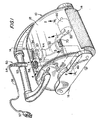
- a pool cleaner preferred to generally as 10 includes an exterior housing 12 fitted with a pump outlet 13 and carrying handle 14.
- Rotating supports or drive means 16 in the form of cylindrical cleaning rollers, support and move the pool cleaner across the bottom or side wall surfaces of the pool to be cleaned.
- a sealed electric drive motor 20 is connected to drive means 16 through a power train (not shown).
- Drive motor electrical leads 22 are connected to battery 40.
- a sealed electric pump motor 30 is connected to a propeller-type impeller through drive shaft 33.
- the pump and its impeller are mounted in axial alignment with the exhaust port 13 mounted in bousing 12.
- the pool cleaner housing 12 also encloses a filter medium through which the water is drawn from the underside of the cleaner and discharged by the movement of impeller 34 through the discharge port 13.
- a filter medium through which the water is drawn from the underside of the cleaner and discharged by the movement of impeller 34 through the discharge port 13.
- Other types of impellers, e.g., turbines create a higher pressure discharge, move to a relatively smaller volume and consume more power.
- the shaft is treated as described above with the friction-reducing lubricant either along its entire length or at those positions which contact the seals. If the shaft is mounted in bearings outside of the motor housing, that portion of the shaft is also preferably treated with the friction-reducing lubricant.
- This treatment has the effect of substantially reducing the power consumption of the pump motor. In operational tests, the power consumption was reduced by as much as about 75%, so that the water pump's power consumption was reduced from about four amps to about one amp.
- the significant reduction in power consumption resulting from the practice of the invention extends the operating time of the pool cleaner by almost four times.
- the power consumption of the drive motor is relatively much less than the power consumed by the water pump when operated under conventional prior art conditions and without the treatment of the water pump drive shaft with the friction-reducing lubricant.
- the invention comprehends the use of a lubricated shaft to minimize frictional losses.
- a further beneficial effect of this reduction in power consumption is to permit the installation of a battery in the interior of a pool cleaner housing that is within the parameters of size and weight that will permit the pool cleaner to be lifted, moved and stored much in the same way as a cleaner of the prior art which receives its power from an external source, i.e., a conventional electric current supply.
- the size and weight of the battery must also be considered in maintaining the negative, but near-neutral buoyancy of the cleaner.
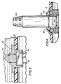
- an inductive charging assembly 50 that comprises an inductive recharging circuit that includes elements that are sealed and waterproof, and that operate at a relatively low voltage.
- An inductive charging port 58 is securely mounted through an opening in housing 12. The port includes a pair of electrical conductors 42 enter the sealed battery case 40 and are secured to the battery charging circuit (not shown).
- a separate power charging element 52 mates with charging port 58 in the charging configuration. Sealed charging element 52 is connected through a power cable 56 to a conventional electrical plug 57.
- the charging element 52 includes a flexible and wear-resistant collar 54 to preclude damage and the loss of the water-tight seal with power cord 56.
- the charging element 52 or the port 58 can be provided with a plurality of frictional ribs, an O-ring, or other construction to maintain proper alignment and a secure fit between these members during charging.
- the pool cleaner is preferably removed from the water and placed away from the pool.
- the inductive charging assembly provides a means for recharging the battery that avoids the need for any exposed metal conductors that might lead to an electrical shock or other injury in the event that the pool cleaner is accidently or inadvertently placed in the pool during charging.
- the inductive element 52 can be handled even when the plug 57 is in a power socket.
- the materials of construction of the charging port 58 and mating charging element 50 are preferably selected from the class of impact-resistant, non-conducting polymers that are resistant to UV radiation and chemicals commonly used in treating the water in the pool.
- the pool cleaner is also provided with a light-emitting indicator that is visible during the battery charging to provide information on the condition of the battery's charge.
- the indicator 44 is a light-emitting diode or similar device mounted on the external surface of the housing 12 or otherwise positioned adjacent an aperture in the housing that will permit the user to determine when the battery is fully charged. Leads 42 extend to the battery 40.
- a manual or automatic shutoff switch can be provided in the circuit between the external power source and the battery to discontinue the charging current to induction element 50 when the battery has reached the desired level of charge.
- the particular arrangement of the drive motor, battery, pump motor, switch and their associated electrical conductors 32 can be varied.
- the preferred embodiment of the invention positions the battery on the interior of the housing in order to minimize turbulence and other hydrodynamic frictional effects, the bartery can be secured in a position which is external to, but attached ⁇ securely in a fixed position to the housing 12.
- the housing typically formed of molded plastic, can be provided with an integral external receptacle or brackets (not shown) for receiving the battery.
- the battery is an integral part of the pool cleaner whether mounted on the exterior or interior of the housing.
- switch 70 mounted in housing 12, is- connected on one side to the battery and at the other side of the switch separate leads 32 extend to the drive motor and pump motor.
- the switch 70 includes an optical sensor in housing 74 that receives ambient light that is transmitted to a photovoltaic element 76 that is in turn linked to the electronic switching device in housing 78.
- the ambient light is at a relatively low level and the switch is in the closed or on allowing power to pass through conductor 79 to the pump and drive motors.
- the photovoltaic layer responds by sending a signal to open the switch and terminal the power transmitted to the two motors.
- the switch 70 can include a light-emitting source in element 78, which light is reflected internally in the sensor housing 74 to a photovoltaic receiving surface 76. While the pool cleaner and sensor are submerged, the optical reflectivity within the sensor is such that the switch is maintained in the closed position and power flows from the battery to the respective motors. When the sensor is removed from the water, the reflectivity is reduced and the light emitted escapes from the housing and the switch circuit is opened so that power flow is discontinued.
- switches including a simple manual toggle switch, can be installed to permit the user to turn the motors on and off.
- a float switch can also be employed, so that when the pool cleaner is removed from the water, the buoyant portion of the switch changes position and the circuit is opened, thereby terminating the power flow from the battery to the motors.
- the inductive charging element 52 is shown positioned in the annular chamber of port 58 for receiving the charging current that is directed to the battery.
- the underside of the port member is provided with leads 42 which, as best seen in FIG. 2 , are connected to the charging circuit of the battery 40.
- the charging element 52 can optionally be provided with an o-ring 53 to assure a secure and stable fit in the annulus 59 during charging.
- the unit In order to maximize the capability of the robotic cleaner to cover the entire bottom surface of the pool to be cleaned, the unit is provided with a microprocessor that has been programmed to direct the cleaner in a particularly efficient pattern of movements.
- the programming and installation of microprocessors and controllers is well known in the art.
- the on-board microprocessor is programmed with an algorithm that results in the following cleaning pattern:
- the pattern of returning a predetermined distance along the most recent path and then stopping to turn a predetermined angle is repeated.
- the counter records the number of contacts with the side walls. After a predetermined number of such side wall contacts have been recorded, the predetermined distance of the reverse leg travel is altered and the routine is continued until the entire bottom area of the pool is contacted and cleaned.
- FIG. 5 An example of this preferred programmed pattern is schematically illustrated in Fig. 5 .
- parallel lines are used to illustrate the reverse leg portion.
- the lines with the arrowheads represent the direction of travel of the unit.
- the angle of rotation illustrated is 90°.
- a novel algorithm that we have developed is incorporated into a microprocessor controller that directs the automated pool cleaner in its cleaning pattern.
- the novel cleaning pattern is the subject of co-pending patent application entitled “Pool Cleaning Method and Apparatus” filed July 29, 2002 naming Porat and Fridman as inventors, and the disclosure of this co-pending application is incorporated herein in its entirety by reference.
- an automated cleaner capable of reversing movement and turning is utilized.
- the unit is initially placed at an arbitrary location on the bottom of pool 110, and the method comprises moving the cleaner in a forward direction until it encounters an upright pool wall 112, reversing the robot until it is a predetermined distance 124 from the wall 112, turning it through a predetermined angle 126 that is less than 180°, and preferably 90° for a rectilinear pool, and continuing to move it until it again encounters an upright wall 116, and then repeating those steps until the unit has encountered upright walls e.g., 118, 112, 114, 118 a predetermined number of times, at which point the predetermined distance is changed e.g.
- a rectangular pool is cleaned by setting the turning angle to 90° and the number of turns before changing the predetermined distance from 125 to 130 is seven.
- the robot has a propeller-type impeller driven in a horizontal plane, and the robot is turned by interrupting motive force to the impeller a plurality of times during a predetermined period to impart a sideways directed bias momentum to the robot.
- FIG. 6 A schematic illustration of the arrangement of elements in the interior of the pool cleaner housing is shown in Fig. 6 .
- the particular position of the controller 86 and central processing unit (CPU) 94 of the microprocessor 80 is not critical.
- the location of the wall sensor 92 schematically illustrated in Fig. 6 , will be understood by one of ordinary skill in the art to be comprised of one or more components with transmitting/receiving elements located at either end of the unit.
- sensors can be mechanical or electro-mechanical, but are preferably electronic, e.g., infrared transmitters which receive signals reflected from the pool's side walls.
- the cleaner can also include a ground position system (GPS) 95 with floating antenna 97 for use in gathering data on the location and way points as the unit traverses the bottom of the pool.
- GPS ground position system
- FIG. 7 A schematic circuit diagram is illustrated in Fig. 7 . Again, the arrangement of elements is merely illustrative and not to scale.
- the electronic elements including the microprocessor CPU 94, controller 86, counter 96, and wall counter 96 and sensor 92 are preferably incorporated into a unitary waterproof housing or assembly for ease and economy of installation and replacement, should that become necessary.
- a global positioning system or "GPS" unit 95 that is also in communication with the CPU and controller.
- GPS global positioning system
- the utilization of GPS units with marine and aircraft navigational systems is well known in the art. It is within the skill of the art to integrate the control of the pool cleaning unit based on the algorithm with a starting set of coordinates provided by the GPS unit.
- the pool cleaner can be manually positioned at one corner of the pool as prescribed by the operating instructions and the GPS coordinate entered into the controller memory. The unit can then be taken to a different location along the pool, e.g., the diagonally opposite corner of a rectangular pool and those GPS coordinates entered.
- the program will then have sufficient information to determine an appropriate path for the unit to follow in order to clean substantially the entire bottom of the pool.
- the entry of the coordinates can be in the way of a manual push button or other similar entry device based on a programming sequence provided to the user in a user's manual.
- the unit will also have to be provided with a floating antenna wire for receiving the GPS signals, or they can be transmitted through a receiver in the power supply.
- Alternate algorithms are provided for round, oval or other shaped pools.
- the microprocessor is provided with a plurality of algorithms and a display or manual switch is provided to permit the seller or user to select the optimum program for the pool to be cleaned.
Landscapes
- Engineering & Computer Science (AREA)
- Architecture (AREA)
- Civil Engineering (AREA)
- Structural Engineering (AREA)
- Electric Vacuum Cleaner (AREA)
- Structures Of Non-Positive Displacement Pumps (AREA)
- Cleaning By Liquid Or Steam (AREA)
Claims (15)
- Batteriebetriebener Tauchschwimmbeckenreiniger (10), umfassend ein Schwimmbeckenreinigergehäuse (12), eine integrale, wiederaufladbare Batterie (40), welche am Gehäuse (12) befestigt ist, und einen Ladeaufbau (50), dadurch gekennzeichnet, dass der Aufbau (50) vom induktiven Ladetyp ist, in welchem ein erster abgedichteter und wasserfester Abschnitt (58) des Aufbaus am Gehäuse (12) befestigt ist und elektrisch mit der Batterie (40) verbunden ist und ein zweiter abgedichteter und wasserfester Abschnitt (52) des Aufbaus elektrisch mit einer externen Stromversorgung verbunden ist und mit dem ersten Abschnitt (58) zum Wiederaufladen der Batterie (40) zusammenpasst.
- Schwimmbeckenreiniger nach Anspruch 1, welcher des Weiteren eine integrale Wasserpumpe umfasst und welcher durch den Ausstoß von Wasser aus der Wasserpumpe bewegt wird.
- Schwimmbeckenreiniger nach Anspruch 1 oder 2, welcher einen programmierten Mikroprozessor (94) und einen Regler (86) umfasst und welcher programmiert ist, sich auf einem allgemein geradlinigen Pfad über die Bodenfläche eines Schwimmbeckens oder Tanks zu bewegen.
- Schwimmbeckenreiniger nach jedem beliebigen der Ansprüche 1-3, in welchem der zweite Abschnitt (52) in einer zusammenpassenden Beziehung in einer Vertiefung des ersten Abschnitts (58) aufgenommen wird.
- Schwimmbeckenreiniger nach Anspruch 4, in welchem der zweite Abschnitt (52) ein Stromkabel (56) umfasst und von wasserfester Bauweise ist.
- Schwimmbeckenreiniger nach jedem beliebigen der vorangehenden Ansprüche, umfassend:einen abgedichteten Wasserpumpenmotor (30), welcher elektrisch mit der Batterie (40) verbunden ist, wobei der Pumpenmotor (30) eine Welle (33) hat, auf der ein Laufrad (34) angebracht ist.
- Schwimmbeckenreiniger nach jedem beliebigen der vorangehenden Ansprüche, wobei die Batterie (40) eine Spannung im Bereich von 6 Volt bis 12 Volt erzeugt.
- Schwimmbeckenreiniger nach Anspruch 6 oder 7, wobei die Batterie (40) mit dem Pumpenmotor (40) über einen Schalter (70) verbunden ist.
- Schwimmbeckenreiniger nach jedem beliebigen der vorangehenden Ansprüche, wobei das Laufrad (34) ein Propeller ist.
- Schwimmbeckenreiniger nach jedem beliebigen der vorangehenden Ansprüche, wobei der Pumpenmotor (30) mit zwölf Volt betrieben wird.
- Schwimmbeckenreiniger nach jedem beliebigen der vorangehenden Ansprüche, wobei die Batterie (40) innerhalb des Gehäuses (12) positioniert ist.
- Schwimmbeckenreiniger nach Anspruch 11, welcher des Weiteren einen Schalter (70) umfasst, der auf dem Gehäuse (12) angebracht ist, wobei der Strom von der Batterie (40) unterbrochen ist, wenn der Schalter (70) in eine Aus-Position bewegt wird.
- Schwimmbeckenreiniger nach Anspruch 12, wobei der Schalter (70) ein lichtempfindlicher optischer Schalter zum Unterbrechen von Strom zum Pumpenmotor (30) und zu einem Antriebsmotor (20) ist.
- Schwimmbeckenreiniger nach Anspruch 12, wobei der Schalter (70) ein Kippschalter ist.
- Schwimmbeckenreiniger nach jedem beliebigen der vorangehenden Ansprüche, welcher des Weiteren einen Antriebsmotor (20) zum Vorantreiben des Schwimmbeckenreinigers umfasst, welcher elektrisch mit der Batterie (40) verbunden ist.
Applications Claiming Priority (3)
| Application Number | Priority Date | Filing Date | Title |
|---|---|---|---|
| US10/218,070 US6842931B2 (en) | 2002-08-12 | 2002-08-12 | Submersible pool cleaner with integral rechargeable battery |
| US218070 | 2002-08-12 | ||
| PCT/US2003/025258 WO2004015223A2 (en) | 2002-08-12 | 2003-08-11 | Submersible pool cleaner with integral rechargeable battery |
Publications (4)
| Publication Number | Publication Date |
|---|---|
| EP1534912A2 EP1534912A2 (de) | 2005-06-01 |
| EP1534912A4 EP1534912A4 (de) | 2007-06-27 |
| EP1534912B1 true EP1534912B1 (de) | 2013-02-20 |
| EP1534912B9 EP1534912B9 (de) | 2013-11-13 |
Family
ID=31495247
Family Applications (1)
| Application Number | Title | Priority Date | Filing Date |
|---|---|---|---|
| EP03785234.0A Expired - Lifetime EP1534912B9 (de) | 2002-08-12 | 2003-08-11 | Tauchschwimmbeckenreiniger mit integraler wiederaufladbarer batterie |
Country Status (6)
| Country | Link |
|---|---|
| US (2) | US6842931B2 (de) |
| EP (1) | EP1534912B9 (de) |
| AU (1) | AU2003258186A1 (de) |
| ES (1) | ES2406754T3 (de) |
| IL (1) | IL165982A (de) |
| WO (1) | WO2004015223A2 (de) |
Families Citing this family (99)
| Publication number | Priority date | Publication date | Assignee | Title |
|---|---|---|---|---|
| GB0003708D0 (en) * | 2000-02-17 | 2000-04-05 | Fisher Power Wave Limited | Power tool |
| ATE452260T1 (de) * | 2001-07-03 | 2010-01-15 | Pentair Pool Products Inc | Untergestell für ein automatisches schwimmbeckenreinigungsgerät |
| IL156535A (en) * | 2003-06-19 | 2006-12-10 | Maytronics Ltd | Pool cleaning apparatus |
| EP1689957A1 (de) * | 2003-10-14 | 2006-08-16 | Maytronics Ltd. | Kabelloser schwimmbeckenreinigungsroboter |
| US7101475B1 (en) * | 2003-12-22 | 2006-09-05 | Terry Antone Maaske | Autonomously navigating solar swimming pool skimmer |
| US7118632B2 (en) * | 2004-05-26 | 2006-10-10 | Aqua-Vac Systems, Inc. | Pool cleaning method and device |
| USD526101S1 (en) * | 2004-08-10 | 2006-08-01 | Zodiac Pool Care Europe Sas | Swimming pool cleaner robot |
| US8007653B2 (en) | 2004-09-15 | 2011-08-30 | Aquatron, Inc. | Method and appartus for operation of pool cleaner with integral chlorine generator |
| CN100365239C (zh) * | 2004-12-30 | 2008-01-30 | 天津望圆工贸有限责任公司 | 泳池自动清洗机 |
| US20060143817A1 (en) * | 2005-01-06 | 2006-07-06 | Automatic Pool Covers, Inc. | Submersible motor |
| USD529669S1 (en) * | 2005-03-21 | 2006-10-03 | Zodiac Pool Care Europe Sas | Swimming pool cleaner robot |
| US20070028405A1 (en) * | 2005-08-04 | 2007-02-08 | Efraim Garti | Pool cleaning robot |
| US20070089228A1 (en) * | 2005-10-24 | 2007-04-26 | Sidler Steven R | Apparatus and Methods for Removing Insects From Swimming Pools and the Like |
| US7690066B2 (en) * | 2005-11-03 | 2010-04-06 | Zodiac Pool Care, Inc. | Automatic pool cleaner |
| WO2008054398A2 (en) | 2005-11-09 | 2008-05-08 | The Trustees Of Columbia University In The City Of New York | Photochemical methods and photoactive compounds for modifying surfaces |
| ITFI20050234A1 (it) * | 2005-11-15 | 2007-05-16 | Fabio Bernini | Pulitore automatico per piscine |
| US7568259B2 (en) * | 2005-12-13 | 2009-08-04 | Jason Yan | Robotic floor cleaner |
| US7437790B1 (en) * | 2006-02-13 | 2008-10-21 | Mike Ajello | Pool cleaning vacuum employing multiple power supply sources and associated method |
| WO2007136831A2 (en) * | 2006-05-17 | 2007-11-29 | Aquatron Inc. | Robotic pool cleaner with internal ultraviolet water sterilization |
| US7621014B2 (en) * | 2006-09-29 | 2009-11-24 | Aquatron Llc | Method for controlling twisting of pool cleaner power cable |
| WO2008066619A1 (en) * | 2006-10-19 | 2008-06-05 | Travis Sparks | Pool light with safety alarm and sensor array |
| US20080099409A1 (en) * | 2006-10-26 | 2008-05-01 | Aquatron Robotic Systems Ltd. | Swimming pool robot |
| US20090056042A1 (en) * | 2007-08-30 | 2009-03-05 | Daniel Pena | Cleaning tool |
| FR2925555B1 (fr) * | 2007-12-21 | 2010-01-22 | Zodiac Pool Care Europe | Appareil nettoyeur de surface immergee a vidange aisee |
| US7867389B2 (en) * | 2008-05-06 | 2011-01-11 | Pool Technology | Pool cleaning vehicle having an advanced drain system |
| CA127298S (en) | 2008-06-23 | 2009-03-30 | Zodiac Pool Care Europe | Swimming pool cleaner robot |
| USD598168S1 (en) * | 2008-09-16 | 2009-08-11 | Hayward Industries, Inc. | Pool cleaner |
| US8343339B2 (en) | 2008-09-16 | 2013-01-01 | Hayward Industries, Inc. | Apparatus for facilitating maintenance of a pool cleaning device |
| USD630809S1 (en) * | 2009-07-01 | 2011-01-11 | Hayward Industries, Inc. | Pool cleaner |
| USD630808S1 (en) * | 2009-07-01 | 2011-01-11 | Hayward Industries, Inc. | Pool cleaner |
| US9593502B2 (en) | 2009-10-19 | 2017-03-14 | Hayward Industries, Inc. | Swimming pool cleaner |
| KR101648348B1 (ko) * | 2010-04-06 | 2016-08-16 | 삼성전자주식회사 | 무선 전력 충전 기능을 구비한 로봇 청소 시스템 및 제어 방법 |
| US8784077B1 (en) * | 2010-04-30 | 2014-07-22 | Brian Ray | Submersible battery operated water pump system |
| CA136282S (en) * | 2010-07-09 | 2011-02-07 | Cristiaan Van Den Heuvel | Compact floating vacuum cleaner |
| US8784652B2 (en) | 2010-09-24 | 2014-07-22 | Poolvergnuegen | Swimming pool cleaner with a rigid debris canister |
| US8869337B2 (en) | 2010-11-02 | 2014-10-28 | Hayward Industries, Inc. | Pool cleaning device with adjustable buoyant element |
| USD654232S1 (en) * | 2010-11-15 | 2012-02-14 | Mjelde Olaf W | Swimming pool cleaner housing |
| CN106639392A (zh) | 2010-12-10 | 2017-05-10 | 亨沃工业公司 | 用于游泳池和水疗场所装备的电源 |
| EP2596733B1 (de) * | 2011-11-22 | 2016-10-19 | Nilfisk A/S | Kombinierte primäre und sekundäre Einheiten |
| JP2013146302A (ja) * | 2012-01-17 | 2013-08-01 | Sharp Corp | 自走式電子機器 |
| EP2669450B1 (de) * | 2012-05-30 | 2015-04-01 | Fabrizio Bernini | Vorrichtung zum Reinigen von Schwimmbecken |
| US9259130B2 (en) | 2012-06-04 | 2016-02-16 | Pentair Water Prool and Spa, Inc. | Pool cleaner light module |
| US9388595B2 (en) * | 2012-07-10 | 2016-07-12 | Aqua Products, Inc. | Pool cleaning system and method to automatically clean surfaces of a pool using images from a camera |
| AU2013312793B2 (en) | 2012-09-04 | 2017-08-10 | Pentair Water Pool And Spa, Inc. | Pool cleaner generator module with magnetic coupling |
| US20140137343A1 (en) * | 2012-11-20 | 2014-05-22 | Aqua Products, Inc. | Pool or tank cleaning vehicle with a powered brush |
| PT2743428T (pt) * | 2012-12-17 | 2020-03-13 | Spectralight Tech Inc | Robô de limpeza de piscina |
| US9903130B2 (en) * | 2012-12-22 | 2018-02-27 | Maytronics Ltd. | Autonomous pool cleaning robot with an external docking station |
| US10111563B2 (en) | 2013-01-18 | 2018-10-30 | Sunpower Corporation | Mechanism for cleaning solar collector surfaces |
| US9073614B2 (en) * | 2013-02-28 | 2015-07-07 | Carl Nettleton | Device and system for cleaning a surface in a marine environment |
| WO2014160312A1 (en) | 2013-03-14 | 2014-10-02 | Hayward Industries, Inc. | Pool cleaner with articulated cleaning members |
| WO2014150506A1 (en) | 2013-03-15 | 2014-09-25 | Hayward Industries, Inc. | Pool cleaning device with wheel drive assemblies |
| WO2015005801A1 (en) * | 2013-07-12 | 2015-01-15 | Ole Molaug Eiendom As | Autonomous device for cleaning a surface of a submerged structure |
| USD742112S1 (en) * | 2013-09-26 | 2015-11-03 | Samsung Electronics Co., Ltd. | Damp cloth for robot cleaner |
| US9091092B1 (en) * | 2014-05-21 | 2015-07-28 | Dongguan Smartpool Prodwcts Incorporated Co Ltd | Pool cleaner |
| MX2016015679A (es) * | 2014-05-30 | 2017-05-15 | Ingenieria Y Marketing S A | Limpiador de fondos y paredes. |
| US9595833B2 (en) * | 2014-07-24 | 2017-03-14 | Seabed Geosolutions B.V. | Inductive power for seismic sensor node |
| USD787760S1 (en) | 2014-11-07 | 2017-05-23 | Hayward Industries, Inc. | Pool cleaner |
| USD789003S1 (en) | 2014-11-07 | 2017-06-06 | Hayward Industries, Inc. | Pool cleaner |
| USD789624S1 (en) | 2014-11-07 | 2017-06-13 | Hayward Industries, Inc. | Pool cleaner |
| USD787761S1 (en) | 2014-11-07 | 2017-05-23 | Hayward Industries, Inc. | Pool cleaner |
| US9399877B2 (en) | 2014-11-21 | 2016-07-26 | Water Tech, LLC | Robotic pool cleaning apparatus |
| US9885196B2 (en) | 2015-01-26 | 2018-02-06 | Hayward Industries, Inc. | Pool cleaner power coupling |
| AU2016211669C1 (en) | 2015-01-26 | 2020-05-07 | Hayward Industries, Inc. | Swimming pool cleaner with hydrocyclonic particle separator and/or six-roller drive system |
| US10107000B2 (en) | 2015-02-24 | 2018-10-23 | Hayward Industries, Inc. | Pool cleaner with optical out-of-water and debris detection |
| US9963896B2 (en) * | 2015-03-17 | 2018-05-08 | Glen Heffernan | Pool cleaner with removable battery pack |
| ES2770925T3 (es) | 2015-03-23 | 2020-07-03 | Aqua Products Inc | Limpiador de piscinas robótico autopropulsado con conjunto de lavado a presión para levantar residuos de una superficie por debajo del limpiador de piscinas |
| FR3035906B1 (fr) * | 2015-05-07 | 2020-03-27 | Zodiac Pool Care Europe | Appareil nettoyeur de piscine a pilotage optimise |
| FR3041982B1 (fr) * | 2015-10-05 | 2017-11-24 | Max Roumagnac | Robot de nettoyage de piscine autonome |
| CN105774933B (zh) * | 2016-03-22 | 2018-01-26 | 京东方科技集团股份有限公司 | 移动平台和移动平台的工作方法 |
| ES2897978T3 (es) * | 2016-09-13 | 2022-03-03 | Maytronics Ltd | Robots de limpieza de piscinas maestros y esclavos |
| CA3096011A1 (en) * | 2017-04-04 | 2018-10-11 | Nc Brands L.P. | Pool cleaner with gear drive and related apparatus and methods |
| US10214933B2 (en) | 2017-05-11 | 2019-02-26 | Hayward Industries, Inc. | Pool cleaner power supply |
| US10227081B2 (en) * | 2017-05-11 | 2019-03-12 | Hayward Industries, Inc. | Pool cleaner caddy with retention mechanism |
| US10161153B2 (en) | 2017-05-11 | 2018-12-25 | Hayward Industries, Inc. | Pool cleaner canister handle |
| US9896858B1 (en) | 2017-05-11 | 2018-02-20 | Hayward Industries, Inc. | Hydrocyclonic pool cleaner |
| US9885194B1 (en) | 2017-05-11 | 2018-02-06 | Hayward Industries, Inc. | Pool cleaner impeller subassembly |
| US10189490B2 (en) | 2017-05-11 | 2019-01-29 | Hayward Industries, Inc. | Pool cleaner caddy with removable wheel assemblies |
| US10676950B2 (en) | 2017-05-11 | 2020-06-09 | Hayward Industries, Inc. | Pool cleaner roller latch |
| US10364905B2 (en) | 2017-05-11 | 2019-07-30 | Hayward Industries, Inc. | Pool cleaner check valve |
| US10156083B2 (en) | 2017-05-11 | 2018-12-18 | Hayward Industries, Inc. | Pool cleaner power coupling |
| US10294686B1 (en) | 2018-04-24 | 2019-05-21 | Water Tech, LLC | Rechargeable robotic pool cleaning apparatus |
| EP3811492A4 (de) | 2018-06-20 | 2022-03-23 | Hayward Industries, Inc. | Stromversorgungen für schwimmbad- und spa-ausrüstung |
| US11634224B2 (en) | 2019-06-03 | 2023-04-25 | Zodiac Pool Systems Llc | Aerial delivery of chemicals for swimming pools and spas |
| CN211286841U (zh) * | 2019-07-31 | 2020-08-18 | 贝尔格莱维亚伍德有限公司 | 用于地上水池的浮力清洁装置 |
| US12084640B2 (en) | 2019-11-21 | 2024-09-10 | ExxonMobil Technology and Engineering Company | Autonomous submersible device for algae growth and collection |
| WO2022153191A1 (en) * | 2021-01-14 | 2022-07-21 | Zodiac Pool Care Europe | Battery powered automatic swimming pool cleaners and associate components |
| AU2022225747A1 (en) * | 2021-02-23 | 2023-05-25 | Zodiac Pool Care Europe | Wireless automatic swimming pool cleaners and associated systems and methods |
| US20240183183A1 (en) * | 2021-03-09 | 2024-06-06 | Maytronics Ltd. | Pool cleaning system having a floating unit |
| EP4347975A1 (de) | 2021-06-03 | 2024-04-10 | Zodiac Pool Care Europe | Elektrische verbinder zur positionierung an, an, in oder in den körpern von automatischen schwimmbeckenreinigern |
| WO2023150938A1 (en) * | 2022-02-09 | 2023-08-17 | Beijing Smorobot Technology Co., Ltd | Pool cleaning robot with charing assembly |
| EP4499953A1 (de) * | 2022-03-29 | 2025-02-05 | Zodiac Pool Care Europe | Automatische schwimmbeckenreinigungssysteme mit verbesserter visueller kommunikation |
| CN218769862U (zh) * | 2022-10-11 | 2023-03-28 | 深圳市思傲拓科技有限公司 | 一种游泳池机器人电池安装结构及游泳池机器人 |
| CN115822335A (zh) * | 2022-10-31 | 2023-03-21 | 浙江明峰工贸股份有限公司 | 带有转向的泳池清洗车 |
| AU2023378955A1 (en) * | 2022-11-10 | 2025-05-29 | Bwt Robotics Pool & Spa Ltd. | Adaptable pool cleaning robot |
| USD1022362S1 (en) * | 2022-11-22 | 2024-04-09 | Degrii Co., Ltd. | Swimming pool cleaner with controller |
| CN219151050U (zh) * | 2023-02-23 | 2023-06-09 | 星迈创新科技(苏州)有限公司 | 水池清洁机器人 |
| WO2024174864A1 (zh) | 2023-02-23 | 2024-08-29 | 星迈创新科技(苏州)有限公司 | 一种清洁设备 |
| CN219638512U (zh) * | 2023-03-22 | 2023-09-05 | 宁波市普世达泳池用品有限公司 | 一种水池吸污器 |
| CN221609644U (zh) * | 2023-10-20 | 2024-08-27 | 宁波市普世达泳池用品有限公司 | 一种电动机器人 |
Family Cites Families (5)
| Publication number | Priority date | Publication date | Assignee | Title |
|---|---|---|---|---|
| US5056213A (en) * | 1985-10-11 | 1991-10-15 | Reliance Electric Industrial Company | Method of assembling a gearmotor and housing |
| US4962559A (en) * | 1988-11-16 | 1990-10-16 | Rainbow Lifegard Products, Inc. | Submersible vacuum cleaner |
| US5128031A (en) * | 1990-04-11 | 1992-07-07 | Marking Designs, Inc. | Pool surface skimmer |
| US6299699B1 (en) * | 1999-04-01 | 2001-10-09 | Aqua Products Inc. | Pool cleaner directional control method and apparatus |
| FR2818680B1 (fr) * | 2000-12-21 | 2003-04-04 | Zodiac Pool Care Europe | Appareil roulant automoteur nettoyeur de surface immergee |
-
2002
- 2002-08-12 US US10/218,070 patent/US6842931B2/en not_active Expired - Lifetime
-
2003
- 2003-08-11 AU AU2003258186A patent/AU2003258186A1/en not_active Abandoned
- 2003-08-11 ES ES03785234T patent/ES2406754T3/es not_active Expired - Lifetime
- 2003-08-11 WO PCT/US2003/025258 patent/WO2004015223A2/en not_active Ceased
- 2003-08-11 EP EP03785234.0A patent/EP1534912B9/de not_active Expired - Lifetime
-
2004
- 2004-02-09 US US10/775,730 patent/US7143502B2/en not_active Expired - Fee Related
- 2004-12-24 IL IL165982A patent/IL165982A/en active IP Right Grant
Also Published As
| Publication number | Publication date |
|---|---|
| ES2406754T9 (es) | 2013-11-28 |
| ES2406754T3 (es) | 2013-06-10 |
| US20040025268A1 (en) | 2004-02-12 |
| EP1534912A2 (de) | 2005-06-01 |
| IL165982A0 (en) | 2006-01-15 |
| AU2003258186A8 (en) | 2004-02-25 |
| US7143502B2 (en) | 2006-12-05 |
| WO2004015223A2 (en) | 2004-02-19 |
| US6842931B2 (en) | 2005-01-18 |
| AU2003258186A1 (en) | 2004-02-25 |
| EP1534912A4 (de) | 2007-06-27 |
| US20040168299A1 (en) | 2004-09-02 |
| WO2004015223A3 (en) | 2004-05-13 |
| IL165982A (en) | 2008-08-07 |
| EP1534912B9 (de) | 2013-11-13 |
Similar Documents
| Publication | Publication Date | Title |
|---|---|---|
| EP1534912B9 (de) | Tauchschwimmbeckenreiniger mit integraler wiederaufladbarer batterie | |
| US11299899B2 (en) | Autonomous cleaning systems principally for swimming pools | |
| US10214932B2 (en) | Robotic pool cleaning apparatus | |
| EP1122382B1 (de) | Robotisierter Schwimmbeckenreiniger | |
| US20070094817A1 (en) | Automatic pool cleaner | |
| US20070067930A1 (en) | Cordless pool cleaning robot | |
| US9502907B2 (en) | Power supplies for pool and spa equipment | |
| US20240183183A1 (en) | Pool cleaning system having a floating unit | |
| US20060060513A1 (en) | Surface pool skimmer | |
| US12385272B2 (en) | Mobile nozzles and associated systems for cleaning pools and spas | |
| CN210734463U (zh) | 一种水上救援设备 | |
| CN115459020A (zh) | 可适应多种供电方式的控制装置、水下清洁装置及方法 | |
| CN113089751A (zh) | 一种水底智能清理装置 | |
| US20250207423A1 (en) | Underwater Pool Cleaning Robot with attached Solar Panel | |
| CN116641587A (zh) | 一种方便更换电池的泳池清洁机器人 | |
| KR200371393Y1 (ko) | 공압 동력을 이용한 수영장 청소로봇 장치 | |
| KR100663337B1 (ko) | 공압 동력을 이용한 수영장 청소로봇 장치 | |
| EP4499954A1 (de) | Automatisches ladesystem für schwimmbeckenreiniger mit korrosionsminderung |
Legal Events
| Date | Code | Title | Description |
|---|---|---|---|
| PUAI | Public reference made under article 153(3) epc to a published international application that has entered the european phase |
Free format text: ORIGINAL CODE: 0009012 |
|
| 17P | Request for examination filed |
Effective date: 20050114 |
|
| AK | Designated contracting states |
Kind code of ref document: A2 Designated state(s): AT BE BG CH CY CZ DE DK EE ES FI FR GB GR HU IE IT LI LU MC NL PT RO SE SI SK TR |
|
| AX | Request for extension of the european patent |
Extension state: AL LT LV MK |
|
| DAX | Request for extension of the european patent (deleted) | ||
| RIN1 | Information on inventor provided before grant (corrected) |
Inventor name: FRIDMAN, IGOR Inventor name: PORAT, JOSEPH |
|
| A4 | Supplementary search report drawn up and despatched |
Effective date: 20070530 |
|
| 17Q | First examination report despatched |
Effective date: 20100719 |
|
| GRAP | Despatch of communication of intention to grant a patent |
Free format text: ORIGINAL CODE: EPIDOSNIGR1 |
|
| GRAS | Grant fee paid |
Free format text: ORIGINAL CODE: EPIDOSNIGR3 |
|
| GRAP | Despatch of communication of intention to grant a patent |
Free format text: ORIGINAL CODE: EPIDOSNIGR1 |
|
| GRAA | (expected) grant |
Free format text: ORIGINAL CODE: 0009210 |
|
| AK | Designated contracting states |
Kind code of ref document: B1 Designated state(s): AT BE BG CH CY CZ DE DK EE ES FI FR GB GR HU IE IT LI LU MC NL PT RO SE SI SK TR |
|
| REG | Reference to a national code |
Ref country code: GB Ref legal event code: FG4D |
|
| REG | Reference to a national code |
Ref country code: CH Ref legal event code: EP |
|
| REG | Reference to a national code |
Ref country code: AT Ref legal event code: REF Ref document number: 597651 Country of ref document: AT Kind code of ref document: T Effective date: 20130315 |
|
| REG | Reference to a national code |
Ref country code: IE Ref legal event code: FG4D |
|
| REG | Reference to a national code |
Ref country code: DE Ref legal event code: R096 Ref document number: 60343328 Country of ref document: DE Effective date: 20130418 |
|
| REG | Reference to a national code |
Ref country code: ES Ref legal event code: FG2A Ref document number: 2406754 Country of ref document: ES Kind code of ref document: T3 Effective date: 20130610 |
|
| REG | Reference to a national code |
Ref country code: AT Ref legal event code: MK05 Ref document number: 597651 Country of ref document: AT Kind code of ref document: T Effective date: 20130220 |
|
| REG | Reference to a national code |
Ref country code: NL Ref legal event code: VDEP Effective date: 20130220 |
|
| PG25 | Lapsed in a contracting state [announced via postgrant information from national office to epo] |
Ref country code: AT Free format text: LAPSE BECAUSE OF FAILURE TO SUBMIT A TRANSLATION OF THE DESCRIPTION OR TO PAY THE FEE WITHIN THE PRESCRIBED TIME-LIMIT Effective date: 20130220 Ref country code: SE Free format text: LAPSE BECAUSE OF FAILURE TO SUBMIT A TRANSLATION OF THE DESCRIPTION OR TO PAY THE FEE WITHIN THE PRESCRIBED TIME-LIMIT Effective date: 20130220 Ref country code: BG Free format text: LAPSE BECAUSE OF FAILURE TO SUBMIT A TRANSLATION OF THE DESCRIPTION OR TO PAY THE FEE WITHIN THE PRESCRIBED TIME-LIMIT Effective date: 20130520 |
|
| PG25 | Lapsed in a contracting state [announced via postgrant information from national office to epo] |
Ref country code: GR Free format text: LAPSE BECAUSE OF FAILURE TO SUBMIT A TRANSLATION OF THE DESCRIPTION OR TO PAY THE FEE WITHIN THE PRESCRIBED TIME-LIMIT Effective date: 20130521 Ref country code: FI Free format text: LAPSE BECAUSE OF FAILURE TO SUBMIT A TRANSLATION OF THE DESCRIPTION OR TO PAY THE FEE WITHIN THE PRESCRIBED TIME-LIMIT Effective date: 20130220 Ref country code: SI Free format text: LAPSE BECAUSE OF FAILURE TO SUBMIT A TRANSLATION OF THE DESCRIPTION OR TO PAY THE FEE WITHIN THE PRESCRIBED TIME-LIMIT Effective date: 20130220 Ref country code: PT Free format text: LAPSE BECAUSE OF FAILURE TO SUBMIT A TRANSLATION OF THE DESCRIPTION OR TO PAY THE FEE WITHIN THE PRESCRIBED TIME-LIMIT Effective date: 20130620 Ref country code: BE Free format text: LAPSE BECAUSE OF FAILURE TO SUBMIT A TRANSLATION OF THE DESCRIPTION OR TO PAY THE FEE WITHIN THE PRESCRIBED TIME-LIMIT Effective date: 20130220 |
|
| PG25 | Lapsed in a contracting state [announced via postgrant information from national office to epo] |
Ref country code: CZ Free format text: LAPSE BECAUSE OF FAILURE TO SUBMIT A TRANSLATION OF THE DESCRIPTION OR TO PAY THE FEE WITHIN THE PRESCRIBED TIME-LIMIT Effective date: 20130220 Ref country code: NL Free format text: LAPSE BECAUSE OF FAILURE TO SUBMIT A TRANSLATION OF THE DESCRIPTION OR TO PAY THE FEE WITHIN THE PRESCRIBED TIME-LIMIT Effective date: 20130220 Ref country code: EE Free format text: LAPSE BECAUSE OF FAILURE TO SUBMIT A TRANSLATION OF THE DESCRIPTION OR TO PAY THE FEE WITHIN THE PRESCRIBED TIME-LIMIT Effective date: 20130220 Ref country code: RO Free format text: LAPSE BECAUSE OF FAILURE TO SUBMIT A TRANSLATION OF THE DESCRIPTION OR TO PAY THE FEE WITHIN THE PRESCRIBED TIME-LIMIT Effective date: 20130220 Ref country code: DK Free format text: LAPSE BECAUSE OF FAILURE TO SUBMIT A TRANSLATION OF THE DESCRIPTION OR TO PAY THE FEE WITHIN THE PRESCRIBED TIME-LIMIT Effective date: 20130220 Ref country code: SK Free format text: LAPSE BECAUSE OF FAILURE TO SUBMIT A TRANSLATION OF THE DESCRIPTION OR TO PAY THE FEE WITHIN THE PRESCRIBED TIME-LIMIT Effective date: 20130220 |
|
| PG25 | Lapsed in a contracting state [announced via postgrant information from national office to epo] |
Ref country code: CY Free format text: LAPSE BECAUSE OF FAILURE TO SUBMIT A TRANSLATION OF THE DESCRIPTION OR TO PAY THE FEE WITHIN THE PRESCRIBED TIME-LIMIT Effective date: 20130220 |
|
| PLBE | No opposition filed within time limit |
Free format text: ORIGINAL CODE: 0009261 |
|
| STAA | Information on the status of an ep patent application or granted ep patent |
Free format text: STATUS: NO OPPOSITION FILED WITHIN TIME LIMIT |
|
| 26N | No opposition filed |
Effective date: 20131121 |
|
| REG | Reference to a national code |
Ref country code: DE Ref legal event code: R097 Ref document number: 60343328 Country of ref document: DE Effective date: 20131121 |
|
| REG | Reference to a national code |
Ref country code: CH Ref legal event code: PL |
|
| GBPC | Gb: european patent ceased through non-payment of renewal fee |
Effective date: 20130811 |
|
| PG25 | Lapsed in a contracting state [announced via postgrant information from national office to epo] |
Ref country code: CH Free format text: LAPSE BECAUSE OF NON-PAYMENT OF DUE FEES Effective date: 20130831 Ref country code: LI Free format text: LAPSE BECAUSE OF NON-PAYMENT OF DUE FEES Effective date: 20130831 Ref country code: MC Free format text: LAPSE BECAUSE OF FAILURE TO SUBMIT A TRANSLATION OF THE DESCRIPTION OR TO PAY THE FEE WITHIN THE PRESCRIBED TIME-LIMIT Effective date: 20130220 |
|
| REG | Reference to a national code |
Ref country code: IE Ref legal event code: MM4A |
|
| PG25 | Lapsed in a contracting state [announced via postgrant information from national office to epo] |
Ref country code: GB Free format text: LAPSE BECAUSE OF NON-PAYMENT OF DUE FEES Effective date: 20130811 Ref country code: IE Free format text: LAPSE BECAUSE OF NON-PAYMENT OF DUE FEES Effective date: 20130811 |
|
| PG25 | Lapsed in a contracting state [announced via postgrant information from national office to epo] |
Ref country code: TR Free format text: LAPSE BECAUSE OF FAILURE TO SUBMIT A TRANSLATION OF THE DESCRIPTION OR TO PAY THE FEE WITHIN THE PRESCRIBED TIME-LIMIT Effective date: 20130220 |
|
| PG25 | Lapsed in a contracting state [announced via postgrant information from national office to epo] |
Ref country code: LU Free format text: LAPSE BECAUSE OF NON-PAYMENT OF DUE FEES Effective date: 20130811 Ref country code: HU Free format text: LAPSE BECAUSE OF FAILURE TO SUBMIT A TRANSLATION OF THE DESCRIPTION OR TO PAY THE FEE WITHIN THE PRESCRIBED TIME-LIMIT; INVALID AB INITIO Effective date: 20030811 |
|
| REG | Reference to a national code |
Ref country code: FR Ref legal event code: PLFP Year of fee payment: 14 |
|
| REG | Reference to a national code |
Ref country code: FR Ref legal event code: PLFP Year of fee payment: 15 |
|
| REG | Reference to a national code |
Ref country code: FR Ref legal event code: PLFP Year of fee payment: 16 |
|
| PGFP | Annual fee paid to national office [announced via postgrant information from national office to epo] |
Ref country code: IT Payment date: 20220819 Year of fee payment: 20 Ref country code: ES Payment date: 20220901 Year of fee payment: 20 Ref country code: DE Payment date: 20220829 Year of fee payment: 20 |
|
| PGFP | Annual fee paid to national office [announced via postgrant information from national office to epo] |
Ref country code: FR Payment date: 20220825 Year of fee payment: 20 |
|
| P01 | Opt-out of the competence of the unified patent court (upc) registered |
Effective date: 20230525 |
|
| REG | Reference to a national code |
Ref country code: DE Ref legal event code: R071 Ref document number: 60343328 Country of ref document: DE |
|
| REG | Reference to a national code |
Ref country code: ES Ref legal event code: FD2A Effective date: 20230825 |
|
| PG25 | Lapsed in a contracting state [announced via postgrant information from national office to epo] |
Ref country code: ES Free format text: LAPSE BECAUSE OF EXPIRATION OF PROTECTION Effective date: 20230812 |