EP1534039B1 - Gerät und Verfahren zum Senden und Empfangen von gemeinsamen Kontrolleninformationen in einem drahtlosen Kommunikationssystem - Google Patents
Gerät und Verfahren zum Senden und Empfangen von gemeinsamen Kontrolleninformationen in einem drahtlosen Kommunikationssystem Download PDFInfo
- Publication number
- EP1534039B1 EP1534039B1 EP04027565A EP04027565A EP1534039B1 EP 1534039 B1 EP1534039 B1 EP 1534039B1 EP 04027565 A EP04027565 A EP 04027565A EP 04027565 A EP04027565 A EP 04027565A EP 1534039 B1 EP1534039 B1 EP 1534039B1
- Authority
- EP
- European Patent Office
- Prior art keywords
- control information
- common control
- mcs
- modulation
- base station
- Prior art date
- Legal status (The legal status is an assumption and is not a legal conclusion. Google has not performed a legal analysis and makes no representation as to the accuracy of the status listed.)
- Expired - Fee Related
Links
Images


Classifications
-
- H—ELECTRICITY
- H04—ELECTRIC COMMUNICATION TECHNIQUE
- H04W—WIRELESS COMMUNICATION NETWORKS
- H04W48/00—Access restriction; Network selection; Access point selection
- H04W48/08—Access restriction or access information delivery, e.g. discovery data delivery
- H04W48/12—Access restriction or access information delivery, e.g. discovery data delivery using downlink control channel
-
- H—ELECTRICITY
- H04—ELECTRIC COMMUNICATION TECHNIQUE
- H04L—TRANSMISSION OF DIGITAL INFORMATION, e.g. TELEGRAPHIC COMMUNICATION
- H04L1/00—Arrangements for detecting or preventing errors in the information received
- H04L1/0001—Systems modifying transmission characteristics according to link quality, e.g. power backoff
- H04L1/0002—Systems modifying transmission characteristics according to link quality, e.g. power backoff by adapting the transmission rate
- H04L1/0003—Systems modifying transmission characteristics according to link quality, e.g. power backoff by adapting the transmission rate by switching between different modulation schemes
- H04L1/0004—Systems modifying transmission characteristics according to link quality, e.g. power backoff by adapting the transmission rate by switching between different modulation schemes applied to control information
-
- H—ELECTRICITY
- H04—ELECTRIC COMMUNICATION TECHNIQUE
- H04L—TRANSMISSION OF DIGITAL INFORMATION, e.g. TELEGRAPHIC COMMUNICATION
- H04L1/00—Arrangements for detecting or preventing errors in the information received
- H04L1/0001—Systems modifying transmission characteristics according to link quality, e.g. power backoff
- H04L1/0009—Systems modifying transmission characteristics according to link quality, e.g. power backoff by adapting the channel coding
- H04L1/001—Systems modifying transmission characteristics according to link quality, e.g. power backoff by adapting the channel coding applied to control information
-
- H—ELECTRICITY
- H04—ELECTRIC COMMUNICATION TECHNIQUE
- H04L—TRANSMISSION OF DIGITAL INFORMATION, e.g. TELEGRAPHIC COMMUNICATION
- H04L1/00—Arrangements for detecting or preventing errors in the information received
- H04L1/0001—Systems modifying transmission characteristics according to link quality, e.g. power backoff
- H04L1/0015—Systems modifying transmission characteristics according to link quality, e.g. power backoff characterised by the adaptation strategy
- H04L1/0017—Systems modifying transmission characteristics according to link quality, e.g. power backoff characterised by the adaptation strategy where the mode-switching is based on Quality of Service requirement
-
- H—ELECTRICITY
- H04—ELECTRIC COMMUNICATION TECHNIQUE
- H04L—TRANSMISSION OF DIGITAL INFORMATION, e.g. TELEGRAPHIC COMMUNICATION
- H04L1/00—Arrangements for detecting or preventing errors in the information received
- H04L2001/0092—Error control systems characterised by the topology of the transmission link
- H04L2001/0093—Point-to-multipoint
-
- H—ELECTRICITY
- H04—ELECTRIC COMMUNICATION TECHNIQUE
- H04L—TRANSMISSION OF DIGITAL INFORMATION, e.g. TELEGRAPHIC COMMUNICATION
- H04L1/00—Arrangements for detecting or preventing errors in the information received
- H04L2001/0098—Unequal error protection
Definitions
- the present invention relates generally to a wireless communication system, and in particular, to an apparatus and method for transmitting and receiving common control information applied in common to subscriber stations.
- a current 3 rd generation (3G) communication system generally supports a data rate of about 384 Kbps in an outdoor channel environment having a relatively poor channel environment, and supports a data rate of a maximum of 2 Mbps in an indoor channel environment having a relatively good channel environment.
- a Wireless Local Area Network (LAN) communication system and a Wireless Metropolitan Area Network (MAN) communication system generally support a data rate of 20 to 50 Mbps. Therefore, in the current 4G communication system, active research is being carried out on a new communication system securing mobility and QoS for the Wireless LAN communication system and the Wireless MAN communication system supporting a relatively high data rate in order to support a high-speed service.
- LAN Local Area Network
- MAN Wireless Metropolitan Area Network
- the Wireless MAN communication system more specifically, a Broadband Wireless Access (BWA) communication system, has wider coverage and supports a higher data rate, compared with the Wireless LAN communication system.
- An Institute of Electrical and Electronics Engineers (IEEE) 802.16a communication system utilizes Orthogonal Frequency Division Multiplexing (OFDM) scheme and/or Orthogonal Frequency Division Multiple Access (OFDMA) scheme to support a broadband transmission network for a physical channel of the Wireless MAN communication system.
- the IEEE 802.16a communication system is a BWA communication system using OFDM/OFDMA scheme.
- FIG. 1 is a diagram schematically illustrating a conventional IEEE 802.16a communication system.
- the IEEE 802.16a communication system has a single-cell configuration, and includes a base station (BS) 100 and a plurality of subscriber stations (SSs), i.e., a first subscriber station(SS#1) 110, a second subscriber station(SS#2) 120, a third subscriber station(SS#3) 130, a fourth subscriber station(SS#4) 140, and a fifth subscriber station(SS#5) 150, which are controlled by the base station 100.
- Signal exchange between the base station 100 and the subscriber stations 110, 120, 130, 140, and 150 is performed using OFDM/OFDMA scheme.
- the subscriber stations 110, 120, 130, 140, and 150 are different distances from the base station 100, and generally, radio wave environments, i.e., channel states, of the subscriber stations 110, 120, 130, 140, and 150 are different according to the distances from the base station 100. That is, the first subscriber station 110, which is the shortest distance from the base station 100, has the best channel state, and the fifth subscriber station 150, which has the longest distance from the base station 100, has the worst channel state.
- the channel states will be distinguished into 5 states: 'best' state, 'good' state, 'normal' state, 'bad' state, and 'worst' state.
- a criterion for distinguishing the 5 channel states is based on a threshold for distinguishing channel states provided in the IEEE 802.16a communication system.
- an operation of distinguishing channel states according to the threshold is not directly related to the present invention. Therefore, a detailed description thereof will be omitted herein.
- channel states between the base station 100 and the subscriber stations 110, 120, 130, 140, and 150 are affected by the distances therebetween, and also by the obstacles existing between the base station 100 and the subscriber stations 110, 120, 130, 140 and 150, or interferences caused by other signals, it is assumed in FIG. 1 that the channel states are affected by the distances from the base station 100.
- the current wireless communication system uses a burst characteristic of packet data in allocating radio resources for transmission of the packet data.
- the wireless communication system refers to the IEEE 802.16a communication system.
- the IEEE 802.16a communication system allocates a dedicated channel to a target subscriber station of the circuit data, and transmits the circuit data over the allocated dedicated channel. That is, for transmission of circuit data, the IEEE 802.16a communication system allocates a dedicated radio resource to a subscriber station, and transmits the circuit data over the allocated dedicated radio resource.
- the IEEE 802.16a communication system allocates a shared resource, i.e., a shared channel, rather than allocating the dedicated resource considering efficiency of radio resources, and transmits the packet data over the allocated shared channel. Therefore, a base station dynamically allocates downlink and uplink resources for each of its subscriber stations using a scheduling operation, and provides information on the allocated downlink and uplink resources to each of the subscriber stations in the form of common control information (CCI) every frame.
- CCI common control information
- the IEEE 802.16a communication system modulates and codes a signal to be transmitted to a particular subscriber station using modulation and coding scheme appropriate for a radio ware environment, i.e., a channel state, of the subscriber station.
- WO 98/37713 A presented a system and method for providing a high-level modulation packet control channel and a high-level modulation packet traffic channel in a second generation (2G) mobile phone system, giving D-AMPS+ mobile stations the possibility to select between said high level modulation channels and a low-level modulation packet control channel and a low-level modulation packet traffic channel depending on channel state, whereas D-AMPS enhanced mobile stations could only select said low-level modulation channels.
- an Adaptive Modulation and Coding (AMC) scheme has been proposed as a scheme for transmitting a signal using different modulation and coding scheme according to the channel states between the base station and the subscriber stations. That is, the AMC scheme is a signal transmission scheme for selecting different modulation schemes and coding schemes according to channel states between a cell, or a base station, and subscriber stations, thereby improving efficiency of an entire cell.
- AMC Adaptive Modulation and Coding
- the AMC scheme has a plurality of modulation schemes and a plurality of coding schemes, and modulates/codes a channel signal with a combination of the modulation schemes and coding schemes.
- each of the combinations of the modulation schemes and coding schemes is called "MCSs,” and it is possible to defme a plurality of MCSs of level 1 to level N according to the number of MCSs.
- the AMC scheme is a scheme for adaptively selecting an MCS level according to the channel states between the base station and the subscriber stations, thereby improving efficiency of the entire base station system.
- the IEEE 802.16a communication system controls signal exchange between a base station and subscriber stations according to a channel state of each of the subscriber stations using the AMC scheme.
- common control information such as system information (SI) and resource allocation information should be received in common by all subscriber stations serviced by the base station
- the base station must transmit the common control information with the most robust MCS level so that even the subscriber station having the worst channel state can normally receive the common control information.
- MCS levels provided in the IEEE 802.16a communication system are shown in Table 1.
- Table 1 MCS level index Robust Resource Efficiency (Info bits/Tx bits) 0 Very Robust Lowest 1 Robust Low 2 Normal Normal 3 Weak High 4 Very Weak Highest
- MCS parameters corresponding to the MCS levels are included in a Downlink Channel Descriptor (DCD) message in the case of a downlink, and included in an Uplink Channel Descriptor (UCD) message in the case of an uplink.
- DCD Downlink Channel Descriptor
- UCD Uplink Channel Descriptor
- the IEEE 802.16a communication system uses the MCS level index as a Downlink Interval Usage Code (DIUC) and an Uplink Interval Usage Code (UIUC) for the uplink and downlink.
- DIUC Downlink Interval Usage Code
- UIUC Uplink Interval Usage Code
- the base station 100 may select any one of the 5 MCS levels in transmitting a signal, the first subscriber station 110 can receive the signal without error. However, the base station 100 selects the MCS level 4 among the 5 MCS levels in transmitting a signal to the first subscriber station 110, taking resource efficiency into consideration. However, because the fifth subscriber station 150 has the worst channel state, the base station 100 should select the MCS level 0, which is the most robust MCS level in transmitting a signal to the fifth subscriber station 150, such that the fifth subscriber station 150 can normally receive the signal.
- the base station and the subscriber station In order to perform communication between a base station and a subscriber station, the base station and the subscriber station should exchange signals using the same MCS level. If an MCS level used in the base station is different from an MCS level used in the subscriber station, normal signal exchange between the base station and the subscriber station cannot be achieved. A process of exchanging information on a determined MCS level between the base station and the subscriber station is not directly related to the present invention, therefore, a detailed description thereof will be omitted herein.
- the base station 100 should transmit the common control information with the MCS level 0, which is the most robust MCS level, so that even the subscriber station having the worst channel state, i.e., the fifth subscriber station 150, among the first to fifth subscriber stations 110 to 150 can normally receive the common control information.
- DL_MAP downlink MAP
- UL_MAP uplink MAP
- Information elements (IEs) included in the DL_MAP message are shown in Table 2.
- the DL_MAP message includes a plurality of IEs, i.e., a Management Message Type indicating a type of a transmission message, a PHY (Physical) Synchronization Field established according to a modulation scheme and a demodulation scheme applied to a physical channel to acquire synchronization, a DCD Count indicating a count corresponding a variation in configuration of a Downlink Channel Descript message including a downlink burst profile, a Base Station ID indicating a base station identifier, a Number of DL_MAP Elements n indicating the number of elements following the Base Station ID, DIUC, or an MCS level index for an allocated radio resource block, and a Location Information indicating location information of the radio resource block.
- IEs i.e., a Management Message Type indicating a type of a transmission message, a PHY (Physical) Synchronization Field established according to a modulation scheme and a demodulation scheme applied to a physical channel to acquire synchron
- the UL_MAP message includes a plurality of IEs, i.e., a Management Message Type indicating a type of a transmission message, an Uplink Channel ID indicating an uplink channel ID in use, a UCD Count indicating a count corresponding to a variation in configuration of a UCD message including an uplink burst profile, a Number of UL_MAP Elements n indicating the number of elements following the UCD Count, an Allocation Start Time indicating uplink resource allocation time information, UIUC, or an MCS level index for an allocated radio resource block, a Location Information indicting location information of the radio resource block, and a CID indicating a Connection ID of a subscriber station that will use the allocated radio resource block.
- a Management Message Type indicating a type of a transmission message
- an Uplink Channel ID indicating an uplink channel ID in use
- a UCD Count indicating a count corresponding to a variation in configuration of a UCD message including an uplink burst profile
- the base station 100 transmits the DL_MAP message and the UL_MAP message using the MCS level 4, which is the most robust MCS level, so that the first to fifth subscriber stations 110 to 150 all can normally receive the DL_MAP message and the UL_MAP message.
- the common control information i.e., the DL_MAP message and the UL_MAP message, includes the information that the first to fifth subscriber stations 110 to 150 all should receive in common, an MCS level index for a radio resource block allocated by the base station 100, and location information of the radio resource block.
- n are the information that the first to fifth subscriber stations 110 to 150 all should receive in common, but DIUC and Location Information are not the information that the first to fifth subscriber stations 110 to 150 all should receive in common, but the information that only a corresponding subscriber station should receive.
- Uplink Channel ID In the UL_MAP message, Uplink Channel ID, UCD Count, Number of UL_MAP Elements n, and Allocation Start Time are the information that the first to fifth subscriber stations 110 to 150 all should receive in common, but CID, UIUC and Location Information are not the information that the first to fifth subscriber stations 110 to 150 all should receive in common, but the information that only a corresponding subscriber station should receive.
- FIG. 2 is a diagram schematically illustrating application of AMC in a conventional IEEE 802.16a communication system. Before a description of FIG. 2 is given, it will be assumed that the IEEE 802.16a communication system is identical in configuration to the IEEE 802.16a communication system described with reference to FIG. 1 . As illustrated in FIG. 2
- the base station 100 transmits common control information 211 using the MCS level 0, transmits a first radio resource 213 including data targeting the fourth subscriber station 140 using the MCS level 1, transmits a second radio resource 215 including data targeting the first subscriber station 110 using the MCS level 4, transmits a third radio resource 217 including data targeting the third subscriber station 130 using the MCS level 2, and transmits a fourth radio resource 219 including data targeting the second subscriber station 120 using the MCS level 3.
- the common control information 211 i.e., the DL_MAP message and the UL_MAP message, includes information on the allocated radio resources, i.e., allocation information for the first to fourth radio resources 213 to 219, and although the allocation information for the first to fourth radio resources 213 to 219 can only be received by corresponding subscriber stations, because it is included in the common control information 211, the base station 100 transmits the allocation information for the first to fourth radio resources 213 to 219 using the MCS level 0, which is the most robust MCS level.
- the base station 100 is allowed to transmit information (i.e., DIUC and Location Information) on a downlink radio resource block targeting only the first subscriber station 110 and information (i.e., CID, UIUC, and Location Information) on an uplink radio resource block in the common control information, i.e., the DL_MAP message and the UL_MAP message, using the MCS level 4, but the base station 100 transmits the information (i.e., DIUC and Location Information) on a downlink radio resource block targeting only the first subscriber station 110 and the information (i.e., CID, UIUC, and Location Information) on an uplink radio resource block using the MCS level 0 because they are also common control information.
- information i.e., DIUC and Location Information
- the information (i.e., DIUC and Location Information) on a downlink radio resource block targeting only the first subscriber station 110 and the information (i.e., CID, UIUC, and Location Information) on an uplink radio resource block are transmitted using unnecessarily robust modulation and coding, causing a signaling overhead.
- the information targeting only the first subscriber station 110 has been described by way of example, the information for targeting only any one of the second to fourth subscriber stations 120 to 140 also causes a signaling overhead.
- transmitting the common control information using the most robust MCS level undesirably reduces resource efficiency.
- an object of the present invention to provide an apparatus and method for transmitting and receiving common control information in a wireless communication system.
- a method for transmitting common control information messages from a base station to a plurality of subscriber stations located in a coverage area of the base station in a wireless communication system comprises the steps of transmitting a first common control information message that is commonly transmitted in common to all of the plurality of subscriber stations; and transmitting a plurality of second common control information messages that are individually transmitted to a plurality of groups, wherein the plurality of groups are generated by classifying the plurality of subscriber stations into the plurality of groups using channel states thereof, a second common control information message with lower coding rate and modulation order than other second common control information messages is placed before the other second common control information messages, and a different modulation order and a different coding rate is applied to each of the plurality of second common control information messages.
- an apparatus for transmitting common control information messages in a wireless communication comprises a plurality of subscriber stations; and a base station for transmitting a first common control information message that is commonly transmitted in common to all of the plurality of subscriber stations, and transmitting a plurality of second common control information messages that are individually transmitted to a plurality of groups, wherein the plurality of groups are generated by classifying the plurality of subscriber stations into the plurality of groups using channel states thereof, a second common control information message with lower coding rate and modulation order than other second common control information messages is placed before the other second common control information messages, and a different modulation order and a different coding rate is applied to each of the plurality of second common control information messages.
- a method for receiving common control information messages transmitted from a base station to a plurality of subscriber stations located in a coverage area of the base station in a wireless communication comprises the steps of receiving, from the base station, a first common control information message that is commonly transmitted, in the base station, in common to all of the plurality of subscriber stations; and receiving, from the base station, a plurality of second common control information messages that are individually transmitted, in the base station, to a plurality of groups, wherein the plurality of groups are generated, in the base station, by classifying the plurality of subscriber stations into the plurality of groups using channel states thereof, a second common control information message with lower coding rate and modulation order than other second common control information messages is placed before the other second common control information messages, and a different modulation order and a different coding rate is applied to each of the plurality of second common control information messages.
- an apparatus for receiving common control information messages in a wireless communication comprises a base station; and a plurality of subscriber stations for receiving, from the base station, a first common control information message that is commonly transmitted, in the base station, in common to all of the plurality of subscriber stations, and receiving, from the base station, a plurality of second common control information messages that are individually transmitted, in the base station, to a plurality of groups, wherein the plurality of groups are generated, in the base station, by classifying the plurality of subscriber stations into the plurality of groups using channel states thereof, a second common control information message with lower coding rate and modulation order than other second common control information messages is placed before the other second common control information messages, and a different modulation order and a different coding rate is applied to each of the plurality of second common control information messages.
- the present invention proposes an apparatus and method for increasing resource efficiency by transmitting common control information (CCI) that all subscriber stations (SSs) should commonly receive according to a characteristic of the common control information and channel states of the subscriber stations, using an Adaptive Modulation and Coding (AMC) scheme in a wireless communication system.
- CCI common control information
- SSs subscriber stations
- AMC Adaptive Modulation and Coding
- an Institute of Electrical and Electronics Engineers (IEEE) 802.16a communication system defined by applying an Orthogonal Frequency Division Multiplexing (OFDM) scheme and/or an Orthogonal Frequency Division Multiple Access (OFDMA) scheme to a Metropolitan Area Network (MAN) communication system, which is a Broadband Wireless Access (BWA) communication system, is used as an example of the wireless communication system.
- OFDM Orthogonal Frequency Division Multiplexing
- OFDMA Orthogonal Frequency Division Multiple Access
- the AMC scheme is a scheme for transmitting a signal using different Modulation and Coding Schemes (MCSs) according to channel states between a base station (BS) and subscriber stations. That is, the AMC scheme is a signal transmission scheme for selecting different modulation scheme and coding schemes according to channel states between a cell, or a base station, and subscriber stations, thereby improving efficiency of the entire cell.
- the AMC scheme has a plurality of modulation schemes and a plurality of coding schemes, and modulates/codes a channel signal with a combination of the modulation schemes and coding schemes.
- each of the combinations of the modulation schemes and coding schemes is called “MCS,” and it is possible to defme a plurality of MCSs of level 1 to level N according to the number of MCSs.
- the AMC scheme is a scheme for adaptively selecting an MCS level according to the channel states between the base station and the subscriber stations, thereby improving efficiency of the entire base station system.
- FIG. 3 is a diagram schematically illustrating application of the AMC scheme in the IEEE 802.16a communication system according to the present invention.
- the IEEE 802.16a communication system is identical in configuration to the IEEE 802.16a communication system described with reference to FIG. 1 , except that one subscriber station, i.e., a sixth subscriber station (not shown), is located in the same place as the third subscriber station 130.
- the first subscriber station 110 having the shortest distance from the base station 100 has the best channel state
- the fifth subscriber station 150 having the longest distance from the base station 100 has the worst channel state.
- the channel states will be distinguished into 5 states: 'best' state, 'good' state, 'normal' state, 'bad' state, and 'worst' state.
- the IEEE 802.16a communication system has 5 MCS levels of an MCS level 0 to an MCS level 4 as described with reference to Table 1.
- the common control information can include the downlink MAP (DL_MAP) message and the uplink MAP (UL_MAP) message described with reference to Table 2 and Table 3, or a Hybrid Automatic Retransmission Request MAP (HARQ_MAP) message.
- the HARQ_MAP message includes a compact DL_MAP message and a compact UL_MAP message including some of the information elements (IEs) included in the DL_MAP message and the UL_MAP message.
- IEs included in the compact DL_MAP message and the compact UL_MAP message are not directly related to the present invention, and a detailed description thereof will be omitted herein.
- PHY Physical
- DCD Downlink Channel Descriptor
- DCD Count indicating a count corresponding a variation in configuration of a DCD message including a downlink burst profile
- Base Station ID indicating a base station identifier
- Number of DL_MAP Elements n indicating the number of elements following the Base Station ID are the information that all subscriber stations serviced by the base station 100 should receive in common, but DIUC (Downlink Interval Usage Code), or an MCS level index for an allocated radio resource block
- Location Information indicating location information of the radio resource block are not the information that all of the subscriber stations should receive in common, rather the information that only a corresponding subscriber station should receive.
- an Uplink Channel ID indicating an uplink channel ID in use an Uplink Channel ID indicating an uplink channel ID in use
- a UCD Count indicating a count corresponding to a variation in configuration of a UCD (Uplink Channel Descriptor) message including an uplink burst profile
- a Number of UL_MAP Elements n indicating the number of elements following the UCD Count
- an Allocation Start Time indicating uplink resource allocation time information are the information that all of the subscriber stations should receive in common, but UIUC (Uplink Interval Usage Code), or an MCS level index for an allocated radio resource block
- Location Information indicting location information of the radio resource block and CID(Connection ID(IDentifier) indicating a Connection ID of a subscriber station that will use the allocated radio resource block are not the information that all of the subscriber stations should receive in common, but the information that only a corresponding subscriber station should receive.
- the HARQ_MAP message is not the information that all of the subscriber stations should receive in common
- the base station 100 transmits the information that all subscriber stations serviced by the base station 100 should receive in common, using the MCS level 0, which is the most robust MCS level, and transmits the information that only a corresponding subscriber station should receive, using an MCS level determined according to a channel state of the corresponding subscriber station.
- MCS level which is the most robust MCS level
- the base station 100 transmits a first radio resource 313 including data targeting the fourth subscriber station 140 using the MCS level 1, and transmits a second radio resource 315 including data targeting the first subscriber station 110 using the MCS level 4. Further, the base station 100 transmits a third radio resource 317 including data targeting the third subscriber station 130 and the sixth subscriber station using the MCS level 2, and transmits a fourth radio resource 319 including data targeting the second subscriber station 120 using the MCS level 3.
- the third radio resource 317 includes a part allocated to the third subscriber station 130 and the other part allocated to the sixth subscriber station, such that it is transmitted together with a CID for identifying a target of the data.
- the base station 100 selects an MCS level according to a channel state of a corresponding subscriber station for the information that only the corresponding subscriber station should receive, in the common control information 311. However, because even the information that only the corresponding subscriber station should receive should be guaranteed to have higher reliability than that of normal data other than the control information, the present invention transmits the corresponding information using an MCS level that is lower by 1 level than an MCS level corresponding to a channel state of the corresponding subscriber station. Alternatively, the base station 100 can transmit the information using an MCS level corresponding to a channel state of the corresponding subscriber station. In this case, only the reliability is lowered as compared with when the base station 100 transmits the information using the 1-level-lower MCS level.
- the base station 100 transmits first radio resource allocation information 321, which is to be transmitted only to the fourth subscriber station 140, using the MCS level 0, transmits second radio resource allocation information 323, which is to be transmitted only to the first subscriber station 110, using the MCS level 3, transmits third radio resource allocation information 325, which is to be transmitted only to the third subscriber station 130 and the sixth subscriber station, using the MCS level 1, and transmits fourth radio resource allocation information 327, which is to be transmitted only to the second subscriber station 120, using the MCS level 2.
- the present invention classifies a characteristic of the common control information 311 according to whether all subscriber stations should receive it or only a corresponding subscriber station should receive it.
- the present invention transmits the information that all subscriber stations should receive, using the most robust MCS level, i.e., the MCS level 0, and transmits the information that only a corresponding subscriber station should receive, using an MCS level which is lower by a predetermined level, for example, 1 level, than an MCS level corresponding to a channel state of the corresponding subscriber station, thereby increasing both reliability and resource efficiency.
- FIG. 9 is a diagram schematically illustrating application of AMC in the IEEE 802.16a communication system according to another embodiment of the present invention.
- the IEEE 802.16a communication system is identical in configuration to the IEEE 802.16a communication system described with reference to FIG. 3 . That is, as described with reference to FIG. 3 , the first subscriber station 110 having the shortest distance from the base station 100 has the best channel state, and the fifth subscriber station 150 having the longest distance from the base station 100 has the worst channel state. Also, the sixth subscriber station is located in the same place where the third subscriber station 130 is located, as described with reference to FIG. 3 .
- the first embodiment of the present invention has not separately prescribed the information that all subscriber stations should receive in common, in the common control information.
- radio resource information which is allocation information for radio resources allocated to the corresponding subscriber stations
- decoding information for normally decoding the radio resource allocation information should be included in the common control information.
- the radio resource allocation information is coded according to an MCS level determined depending on a channel state of a corresponding subscriber station, a size and location of the radio resource allocation information is different for respective subscriber stations. Therefore, the base station should inform the subscriber station of the size and location of the radio resource allocation information through the common control information.
- the subscriber station reads the decoding information and decodes the radio resource allocation information with an MCS level corresponding to the size and location of the corresponding radio resource allocation information.
- the term "decoding information" for the radio resource allocation information refers to an MCS level and size and location information of radio resource allocation information corresponding to the MCS level.
- the second embodiment of the present invention is almost identical to the first embodiment of the present invention in method of using AMC, except that the decoding information 929 for the radio resource allocation information is added to the common control information 311 described in connection with FIG. 3 .
- the first and second embodiments are different only in that sizes or locations of the first radio resource allocation information 321 to the fourth radio resource allocation information 327 are different. Therefore, a detailed description of the same parts as those illustrated in FIG. 3 will be omitted herein.
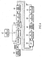
- FIG. 4 is a diagram schematically illustrating a structure of a transmitter for the IEEE 802.16a communication system according to the present invention.
- the transmitter or a base station, includes a radio resource allocator 410, an encoder 411, an interleaver 413, a symbol mapper 415, an AMC controller 417, a serial-to-parallel (S/P) converter 419, a pilot symbol inserter 421, an inverse fast Fourier transform (IFFT) unit 423, a parallel-to-serial (P/S) converter 425, a guard interval inserter 427, a digital-to-analog (D/A) converter 429, and a radio frequency (RF) processor 431.
- a radio resource allocator 410 an encoder 411, an interleaver 413, a symbol mapper 415, an AMC controller 417, a serial-to-parallel (S/P) converter 419, a pilot symbol inserter 421, an inverse fast Four
- the radio resource allocator 410 allocates downlink and uplink resources for receivers, or subscriber stations, generates common control information according to the allocated downlink and uplink resources, and outputs the generated common control information to the encoder 411.
- a process of allocating downlink and uplink resources for the subscriber stations by the radio resource allocator 410 is not directly related to the present invention, and a detailed description thereof will be omitted.
- the encoder 411 codes the common control information using a coding scheme controlled by the AMC controller 417, and outputs the coded common control information to the interleaver 413.
- the AMC controller 417 selects a coding scheme corresponding to the most robust MCS level for the information that all subscriber stations should receive, in the common control information, and selects a coding scheme corresponding to an MCS level, which is lower by 1 level than an MCS level corresponding to a channel state of a corresponding subscriber station for the information that only the corresponding subscriber station should receive, in the common control information.
- the coding scheme is a coding rate.
- the interleaver 413 interleaves the coded common control information using a predetermined interleaving scheme, and outputs the interleaved common control information to the symbol mapper 415.
- a random interleaving scheme can be used for the interleaving scheme.
- the symbol mapper 415 modulates coded bits output from the interleaver 413 into modulation symbols using a modulation scheme controlled by the AMC controller 417, and outputs the modulation symbols to the serial-to-parallel converter 419.
- a modulation scheme controlled by the AMC controller 417 can be used for the modulation scheme
- the AMC controller 417 selects a modulation scheme corresponding to the most robust MCS level for the information that all subscriber stations should receive, in the common control information, and selects a modulation scheme corresponding to an MCS level which is lower by 1 level than an MCS level corresponding to a channel state of a corresponding subscriber station for the information that only the corresponding subscriber station should receive, in the common control information.
- the serial-to-parallel converter 419 parallel-converts serial modulation symbols output from the symbol mapper 415, and outputs the parallel-converted modulation symbols to the pilot symbol inserter 421.
- the pilot symbol inserter 421 inserts pilot symbols into the parallel-converted modulation symbols output from the serial-to-parallel converter 419, and outputs the pilot-inserted modulation symbols to the IFFT unit 423.
- the IFFT unit 423 performs N-point IFFT on the signals output from the pilot symbol inserter 421, and outputs the IFFT-processed signals to the parallel-to-serial converter 425.
- the parallel-to-serial converter 425 serial-converts the signals output from the IFFT unit 423, and outputs the serial-converted signal to the guard interval inserter 427.
- the guard interval inserter 427 inserts a guard interval signal into the signal output from the parallel-to-serial converter 425, and outputs the guard interval-inserted signal to the digital-to-analog converter 429.
- the guard interval is inserted to remove interference between an OFDM symbol transmitted at a previous time and an OFDM symbol transmitted at a current time.
- the guard interval signal is inserted in a cyclic prefix scheme or a cyclic prefix scheme.
- a cyclic prefix scheme a predetermined number of last samples of an OFDM symbol in a time domain are copied and inserted into a valid OFDM symbol
- a cyclic postfix scheme a predetermined number of first samples of an OFDM symbol in a time domain are copied and inserted into a valid OFDM symbol.
- the digital-to-analog converter 429 analog-converts the signal output from the guard interval inserter 427, and outputs the analog-converted signal to the RF processor 431.
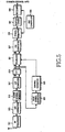
- FIG. 5 is a diagram schematically illustrating a receiver in the IEEE 802.16a communication system according to the present invention.
- the receiver or a subscriber station, includes an RF processor 511, an analog-to-digital (A/D) converter 513, a guard interval remover 515, a serial-to-parallel (S/P) converter 517, a fast Fourier transform (FFT) unit 519, an equalizer 521, a pilot symbol extractor 523, a channel estimator 525, a parallel-to-serial (P/S) converter 527, a symbol demapper 529, a deinterleaver 531, a decoder 533, and an AMC controller 535.
- A/D analog-to-digital
- S/P serial-to-parallel
- FFT fast Fourier transform
- a signal transmitted by the transmitter, or the base station, in the IEEE 802.16a communication system described with reference to FIG. 4 is received via a reception antenna of the receiver, the received signal experiencing a multipath channel and having a noise component.
- the signal received via the reception antenna is input to the RF processor 511, which down-converts the signal received via the reception antenna into an intermediate frequency (IF) signal and outputs the IF signal to the analog-to-digital converter 513.
- the analog-to-digital converter 513 digital-converts an analog signal output from the RF processor 511, and outputs the digital-converted signal to the guard interval remover 515.
- the guard interval remover 515 removes a guard interval signal from the digital-converted signal output from the analog-to-digital converter 513, and outputs the guard interval-removed signal to the serial-to-parallel converter 517.
- the serial-to-parallel converter 517 parallel-converts the serial signal output from the guard interval remover 515, and outputs the parallel-converted signal to the FFT unit 519.
- the FFT unit 519 performs N-point FFT on the signal output from the serial-to-parallel converter 517, and outputs the FFT-processed signal to the equalizer 521 and the pilot symbol extractor 523.
- the equalizer 521 channel-equalizes the signal output from the FFT unit 519, and outputs the channel-equalized signal to the parallel-to-serial converter 527.
- the parallel-to-serial converter 527 serial-converts the parallel signal output from the equalizer 521, and outputs the serial-converted signal to the symbol demapper 529.
- the FFT-processed signal output from the IFFT unit 519 is input to the pilot symbol extractor 523, and the pilot symbol extractor 523 extracts pilot symbols from the FFT-processed signal output from the FFT unit 519, and outputs the extracted pilot symbols to the channel estimator 525.
- the channel estimator 525 performs channel estimation on the extracted pilot symbols output from the pilot symbol extractor 523, and outputs the channel estimation result to the equalizer 521.
- the subscriber station generates channel quality information (CQI) corresponding to the channel estimation result from the channel estimator 525, and transmits the generated CQI to the base station through a CQI transmitter (not shown).
- CQI channel quality information
- the symbol demapper 529 demodulates the signal output from the parallel-to-serial converter 527 using a demodulation scheme corresponding to the modulation scheme used in the base station, and outputs the demodulated signal to the deinterleaver 531.
- Information on the modulation scheme used in the base station is provided from the AMC controller 535, and although not illustrated in FIG. 5 , the AMC controller 535 is provided with separate information on the modulation scheme from the base station.
- the deinterleaver 531 deinterleaves the signal output from the symbol demapper 529 using a deinterleaving scheme corresponding to the interleaving scheme used in the base station, and outputs the deinterleaved signal to the decoder 533.
- the decoder 533 decodes the deinterleaved signal output from the deinterleaver 531 using a decoding scheme corresponding to the coding scheme used in the base station, and outputs the decoded signal as common control information transmitted by the transmitter. Also, information on the coding scheme used in the base station is provided from the AMC controller 535, and although not illustrated in FIG. 5 , the AMC controller 535 is provided with separate information on the coding scheme from the base station.
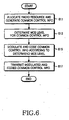
- FIG. 6 is a flowchart illustrating a process of transmitting common control information in the IEEE 802.16a communication system according to the present invention.
- a transmitter, or a base station, of the IEEE 802.16a communication system allocates downlink and uplink resources for a receiver, or a subscriber station, of the IEEE 802.16a communication system, and generates common control information according to the allocated downlink and uplink resources.
- the base station selects an MCS level to be used for the common control information.
- the base station selects the most robust MCS level for the information that all subscriber stations should receive, in the common control information, and selects an MCS level which is lower by 1 level than an MCS level corresponding to a channel state of a corresponding subscriber station for the information that only the corresponding subscriber station should receive, in the common control information.
- the base station includes decoding information for normally decoding the information that only the corresponding subscriber station should receive, i.e., radio resource allocation information, in the common control information, because the radio resource allocation information blocks are coded with different MCS levels.
- step 615 the base station modulates and codes the common control information according to the selected MCS level, and then proceeds to step 617.
- step 617 the base station transmits the modulated coded common control information to subscriber stations through a downlink, and then ends the process.
- FIG. 7 is a flowchart illustrating a process of receiving common control information in the IEEE 802.16a communication system according to the present invention.
- a receiver, or a subscriber station, of the IEEE 802.16a communication system receives a downlink signal.
- the subscriber station detects common control information by multiplexing the received downlink signal. More specifically, in the second embodiment of the present invention, decoding information for decoding radio resource allocation information is included in the common control information.
- the subscriber station demodulates and decodes the detected common control information according to an MCS level used in a base station. More specifically, in the second embodiment of the present invention, the subscriber station demodulates and decodes the detected common control information according to an MCS level used in the base station by a corresponding size in the location of radio resource allocation information that the subscriber station itself should decode according to the decoding information. In this case, the subscriber station can decode the radio resource allocation information at higher reliability.
- step 717 the subscriber station determines if decoding on the common control information is successful. If it is determined that decoding on the common control information is successful, in step 719, the subscriber station performs an operation corresponding to the common control information, i.e., a data reception operation through a radio resource field corresponding to radio resource information included in the common control information, and then ends the process. However, if it is determined in step 717 that decoding on the common control information is not successful,in step 721, the subscriber station discards the decoded information, and ends the process.
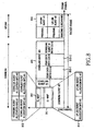
- FIG. 8 is a diagram illustrating a frame format for the IEEE 802.16a communication system according to the first embodiment of the present invention.
- a horizontal axis represents an OFDMA symbol number
- a vertical axis represents a subchannel number.
- one OFDMA frame includes a plurality of, for example, 8 OFDMA symbols.
- One OFDMA symbol includes a plurality of, for example, N subcarrier signals.
- subchannel refers to a channel including a predetermined number of subcarriers.
- the common control information includes a DL_MAP message and a UL_MAP message, or an HARQ_MAP message, and it will be assumed in FIG. 8 that the common control information includes the DL_MAP message and the UL_MAP message.
- FIG. 8 illustrates two cases, i.e., a first case in which the base station 100 transmits common control information and user data to the third subscriber station 130 having a 'normal' channel state and the third subscriber station 130 receives the common control information and the user data, and a second case where the base station 100 transmits common control information to the first subscriber station 110 having a 'best' channel state and the first subscriber station 110 transmits user data over an uplink.
- the base station 100 allocates user data 815-1 of the third subscriber station 130 including a CID A and user data 815-2 of the sixth subscriber station including a CID B, both the third and sixth subscriber stations using the same QoS (Quality-of-Service) level and the same MCS level, to a third downlink burst 815.
- the base station 100 allocates user data and CID of a corresponding subscriber station for each downlink burst needed in one OFDMA frame within an MCS level supported in the IEEE 802.16a communication system.
- the base station 100 maps offset information in units of symbols or subcarrier frequency allocation capable of distinguishing a downlink burst transmitted to the third subscriber station 130, i.e., an MCS level and position information to be used for the third downlink burst 815, to third downlink burst allocation information 813 in the DL_MAP message 812, which is common control information.
- the common control information includes decoding information for decoding radio resource allocation information, i.e., an MCS level and location and size information of radio resource allocation information corresponding to the MCS level.
- decoding information for decoding radio resource allocation information i.e., an MCS level and location and size information of radio resource allocation information corresponding to the MCS level.
- the base station 100 codes and modulates the DL_MAP message 812 and downlink bursts using the corresponding MCS level, and transmits the results to subscriber stations.
- the third subscriber station 130 receives a downlink signal and detects common control information from the received downlink signal. That is, the third subscriber station 130 detects the information that all subscriber stations should receive, i.e., PHY Synchronization, DCD Count, Base Station ID, and Number of DL_MAP Elements n, from the DL_MAP message described in connection with Table 2, by applying the most robust MCS level to the detected common control information. Thereafter, the third subscriber station 130 demodulates and decodes the detected common control information using an MCS level, which is 1 level lower than an MCS level corresponding to a channel state of the third subscriber station 130, in order to acquire downlink burst allocation information for the downlink bursts.
- MCS level which is 1 level lower than an MCS level corresponding to a channel state of the third subscriber station 130
- the third subscriber station 130 decodes first downlink burst allocation information using an MCS level, which is lower by 1 level than an MCS level corresponding to its channel state.
- the third subscriber station 130 fails in decoding due to a difference of the MCS level used for the first downlink burst allocation information, such that it discards the corresponding information.
- the third subscriber station 130 decodes second downlink burst allocation information, third downlink burst allocation information 813, and fourth downlink burst allocation information. Because only the third downlink burst allocation information 813 uses the same MCS level, only the third downlink burst allocation information 813 is normally decoded.
- the third subscriber station 130 accesses a downlink burst corresponding to the third downlink burst allocation information 813, i.e., the third downlink burst 815, and demodulates user data using the same MCS level as an MCS level corresponding to its channel state.
- the third subscriber station 130 detects decoding information for decoding the third downlink burst allocation information 813 representing a location of the third downlink burst 815 from the common control information, and detects location and size of downlink burst allocation information having an MCS level applied thereto. Therefore, the third subscriber station 130 decodes the third downlink burst allocation information 813 with reliability according to the decoding information. That is, the third subscriber station 130 detects the same MCS level as its own MCS level from the decoding information, and decodes information on the corresponding location using the detected MCS level. Accordingly, the third subscriber station 130 normally decodes the third downlink burst allocation information 813.
- the third subscriber station 130 should refer to its own CID, i.e., CID A.
- Uplink burst allocation information can be detected in the method used in detecting the downlink burst allocation information. More specifically, the base station 100 allocates a first uplink burst 816 to the first subscriber station 110 in order to transmit user data to the first subscriber station 110 over an uplink. That is, the base station 100 maps offset information in units of symbol or subcarrier frequency allocation capable of distinguishing an MCS level and position information of the first uplink burst 816, i.e., the uplink burst, together with a CID C of the first subscriber station 110, to the UL_MAP message 811. Thereafter, the base station 100 codes and modulates the UL_MAP message 811 using a corresponding MCS level, and transmits the modulated UL_MAP message to subscriber stations.
- the first subscriber station 110 receives a downlink signal, and detects common control information from the received downlink signal. That is, the first subscriber station 110 detects the information that all subscriber stations should receive, i.e., Uplink Channel ID, UCD Count, Allocation Start Time, and Number of UL_MAP Elements n, from the UL_MAP message 811 described in connection with Table 3, by applying the most robust MCS level to the detected common control information.
- the common control information includes the decoding information, i.e., an MCS level and location and size information for each of uplink burst allocation information corresponding to the MCS level.
- the first subscriber station 110 demodulates and decodes the detected common control information using an MCS level, which is lower by 1 level than an MCS level corresponding to a channel state of the first subscriber station 110, in order to acquire uplink burst allocation information for the uplink bursts.
- the first subscriber station 110 decodes first uplink burst allocation information 814 using an MCS level, which is lower by 1 level than an MCS level corresponding to its channel state. Because the MCS level applied to the first uplink burst allocation information 814 is identical to the MCS level, which is lower by 1 level than the MCS level corresponding to a channel state of the first subscriber station 110, the first subscriber station 110 can normally decode the first uplink burst allocation information. Therefore, the first subscriber station 110 can use an uplink burst according to the first uplink burst allocation information 814, i.e., the first uplink burst 816.
- the first subscriber station 110 detects decoding information for decoding the first uplink burst allocation information 814 representing a location of the first uplink burst 816 from the common control information, and decodes uplink burst allocation information having an MCS level for the first subscriber station 110, i.e., the first uplink burst allocation information 814, according to the decoding information.
- the wireless communication system of the present invention classifies common control information into the information that all subscriber stations should receive in common and the information that only particular subscriber stations should receive, and transmits the classified information using different MCS levels, thereby maximizing efficiency of radio resources.
- the amount of radio resources used for transmission of common control information is minimized, and spare radio resources secured by the minimization are used for transmitting other data, thereby improving performance of the wireless communication system.
Landscapes
- Engineering & Computer Science (AREA)
- Computer Networks & Wireless Communication (AREA)
- Signal Processing (AREA)
- Quality & Reliability (AREA)
- Computer Security & Cryptography (AREA)
- Mobile Radio Communication Systems (AREA)
- Digital Transmission Methods That Use Modulated Carrier Waves (AREA)
Claims (20)
- Verfahren zum Senden von Nachrichten mit gemeinsamen Steuerinformationen von einer Basisstation zu einer Vielzahl von Teilnehmerstationen, die sich in einem Versorgungsbereich der Basisstation in einem Drahtlos-Kommunikationssystem befinden, wobei das Verfahren die folgenden Schritte umfasst:Senden einer ersten Nachricht (311) mit gemeinsamen Steuerinformationen, die gemeinsam zu allen der Vielzahl von Teilnehmerstationen zusammen gesendet wird; undSenden einer Vielzahl zweiter Nachrichten mit gemeinsamen Steuerinformationen (321, 323, 325, 327), die einzeln zu einer Vielzahl von Gruppen gesendet werden,wobei die Vielzahl von Gruppen erzeugt werden, indem die Vielzahl von Teilnehmerstationen unter Verwendung von Kanalzuständen derselben in die Vielzahl von Gruppen eingeteilt werden, eine zweite Nachricht (321) mit gemeinsamen Steuerinformationen mit einer niedrigeren Codierrate und Modulationsordnung als andere zweite Nachrichten (323, 325, 327) mit gemeinsamen Steuerinformationen vor die anderen zweiten Nachrichten (323, 325, 327) mit gemeinsamen Steuerinformationen gesetzt werden und auf jede der Vielzahl zweiter Nachrichten mit gemeinsamen Steuerinformationen eine andere Modulationsordnung und eine andere Codierrate angewendet werden.
- Verfahren nach Anspruch 1, wobei jede der Vielzahl zweiter Nachrichten mit gemeinsamen Steuerinformationen eine Beschreibung eines Standorts sowie ein Codier- und Modulations-Schema für jede der Vielzahl von Gruppen enthält.
- Verfahren nach Anspruch 1, wobei, wenn eine Kombination einer Modulationsordnung und einer Codierrate ein MCS-Pegel (Modulation and Coding Scheme level) ist, jeder der MCS-Pegel, der auf jede der Vielzahl zweiter Nachrichten mit gemeinsamen Steuerinformationen angewendet wird, um einen vorgegebenen Pegel gegenüber einem MCS-Pegel reguliert wird, der dem Kanalzustand jeder der Vielzahl von Gruppen entspricht.
- Verfahren nach Anspruch 3, wobei jeder der regulierten MCS-Pegel identisch mit jedem von MCS-Pegeln, die Kanalzuständen der Vielzahl von Gruppen entsprechen, oder jedem von MCS-Pegeln ist, die Modulationsschemata mit einer niedrigeren Ordnung als die von Modulationsschemata der MCS-Pegel haben, die den Kanalzuständen als Vielzahl von Gruppen entsprechen, und Codierschemata mit niedrigeren Codierraten als Codierschemata der MCS-Pegel haben, die Kanalzuständen der Vielzahl von Gruppen entsprechen.
- Verfahren nach Anspruch 1, wobei, wenn eine Kombination einer Modulationsordnung und einer Codierrate ein MCS-Pegel ist (Modulation and Coding Scheme level), ein MCS-Pegel, der auf die erste Nachricht mit gemeinsamen Steuerinformationen angewendet wird, identisch mit einem MCS-Pegel, der von allen in der Basisstation verfügbaren MCS-Pegeln ein Modulationsschema mit einer niedrigsten Ordnung und ein Codierschema mit einer niedrigsten Codierrate hat, oder einem MCS-Pegel ist, der einem Kanalzustand einer Teilnehmerstation entspricht, die von der Vielzahl von Teilnehmerstationen einen schlechtesten Kanalzustand hat.
- Vorrichtung zum Senden von Nachricht mit gemeinsamen Steuerinformationen in einer Drahtlos-Kommunikation, wobei die Vorrichtung umfasst:eine Vielzahl von Teilnehmerstationen (110, 120, 130, 140, 150); undeine Basisstation (100) zum Senden einer ersten Nachricht (311) mit gemeinsamen Steuerinformationen, die gemeinsam zu allen der Vielzahl von Teilnehmerstationen zusammen gesendet wird, und zum Senden einer Vielzahl zweiter Nachrichten (321, 323, 325, 327) mit gemeinsamen Steuerinformationen, die einzeln zu einer Vielzahl von Gruppen gesendet werden,wobei die Vorrichtung so konfiguriert ist, dass die Vielzahl von Gruppen erzeugt werden, indem die Vielzahl von Teilnehmerstationen unter Verwendung von Kanalzuständen derselben in die Vielzahl von Gruppen eingeteilt werden, eine zweite Nachricht (321) mit gemeinsamen Steuerinformationen mit einer niedrigeren Codierrate und Modulationsordnung als andere zweite Nachrichten (323, 325, 327) mit gemeinsamen Steuerinformationen vor die anderen zweiten Nachrichten (323, 325, 327) mit gemeinsamen Steuerinformationen gesetzt werden und auf jede der Vielzahl zweiter Nachrichten mit gemeinsamen Steuerinformationen eine andere Modulationsordnung und eine andere Codierrate angewendet werden.
- Vorrichtung nach Anspruch 6, wobei jede der Vielzahl zweiter Nachrichten mit gemeinsamen Steuerinformationen eine Beschreibung eines Standorts sowie ein Codier- und Modulations-Schema für jede der Vielzahl von Gruppen enthält.
- Vorrichtung nach Anspruch 6, wobei, wenn eine Kombination einer Modulationsordnung und einer Codierrate ein MCS-Pegel (Modulation and Coding Scheme level) ist, jeder der MCS-Pegel, der auf jede der Vielzahl zweiter Nachrichten mit gemeinsamen Steuerinformationen angewendet wird, um einen vorgegebenen Pegel gegenüber einem MCS-Pegel reguliert wird, der dem Kanalzustand jeder der Vielzahl von Gruppen entspricht.
- Vorrichtung nach Anspruch 8, wobei jeder der regulierten MCS-Pegel identisch mit jedem von MCS-Pegeln, die Kanalzuständen der Vielzahl von Gruppen entsprechen, oder jedem von MCS-Pegeln ist, die Modulationsschemata mit einer niedrigeren Ordnung als die von Modulationsschemata der MCS-Pegel haben, die den Kanalzuständen der Vielzahl von Gruppen entsprechen, und Codierschemata mit niedrigeren Codierraten als Codierschemata der MCS-Pegel haben, die Kanalzuständen der Vielzahl von Gruppen entsprechen.
- Vorrichtung nach Anspruch 6, wobei, wenn eine Kombination einer Modulationsordnung und einer Codierrate ein MCS-Pegel ist (Modulation and Coding Scheme level), ein MCS-Pegel, der auf die erste Nachricht mit gemeinsamen Steuerinformationen angewendet wird, identisch mit einem MCS-Pegel, der von allen in der Basisstation verfügbaren MCS-Pegeln ein Modulationsschema mit einer niedrigsten Ordnung und ein Codierschema mit einer niedrigsten Codierrate hat, oder einem MCS-Pegel ist, der einem Kanalzustand einer Teilnehmerstation entspricht, die von der Vielzahl von Teilnehmerstationen einen schlechtesten Kanalzustand hat.
- Verfahren zum Empfangen von Nachrichten mit gemeinsamen Steuerinformationen, die von einer Basisstation zu einer Vielzahl von Teilnehmerstationen gesendet werden, die sich in einem Versorgungsbereich der Basisstation befinden, in einer Drahtlos-Kommunikation, wobei das Verfahren die folgenden Schritte umfasst:Empfangen einer ersten Nachricht (311) mit gemeinsamen Steuerinformationen, die gemeinsam in der Basisstation zu allen der Vielzahl von Teilnehmerstationen zusammen gesendet wird; undEmpfangen einer Vielzahl zweiter Nachrichten (321, 323, 325, 327) mit gemeinsamen Steuerinformationen von der Basisstation, die in der Basisstation einzeln zu einer Vielzahl von Gruppen gesendet werden,wobei die Vielzahl von Gruppen in der Basisstation erzeugt werden, indem die Vielzahl von Teilnehmerstationen unter Verwendung von Kanalzuständen derselben in die Vielzahl von Gruppen eingeteilt werden, eine zweite Nachricht (321) mit gemeinsamen Steuerinformationen mit einer niedrigeren Codierrate und Modulationsordnung als andere zweite Nachrichten mit gemeinsamen Steuerinformationen vor die anderen zweiten Nachrichten (323, 325, 327) mit gemeinsamen Steuerinformationen gesetzt werden und auf jede der Vielzahl zweiter Nachrichten mit gemeinsamen Steuerinformationen eine andere Modulationsordnung und eine andere Codierrate angewendet werden.
- Verfahren nach Anspruch 11, wobei jede der Vielzahl zweiter Nachrichten mit gemeinsamen Steuerinformationen eine Beschreibung eines Standorts sowie ein Codier- und Modulations-Schema für jede der Vielzahl von Gruppen enthält.
- Verfahren nach Anspruch 11, wobei, wenn eine Kombination einer Modulationsordnung und einer Codierrate ein MCS-Pegel (Modulation and Coding Scheme level) ist, jeder der MCS-Pegel, der auf jede der Vielzahl zweiter Nachrichten mit gemeinsamen Steuerinformationen angewendet wird, um einen vorgegebenen Pegel gegenüber einem MCS-Pegel reguliert wird, der dem Kanalzustand jeder der Vielzahl von Gruppen entspricht.
- Verfahren nach Anspruch 13, wobei jeder der regulierten MCS-Pegel identisch mit jedem von MCS-Pegeln, die Kanalzuständen der Vielzahl von Gruppen entsprechen, oder jedem von MCS-Pegeln ist, die Modulationsschemata mit einer niedrigeren Ordnung als die von Modulationsschemata der MCS-Pegel haben, die den Kanalzuständen der Vielzahl von Gruppen entsprechen, und Codierschemata mit niedrigeren Codierraten als Codierschemata der MCS-Pegel haben, die Kanalzuständen der Vielzahl von Gruppen entsprechen.
- Verfahren nach Anspruch 11, wobei, wenn eine Kombination einer Modulationsordnung und einer Codierrate ein MCS-Pegel ist (Modulation and Coding Scheme level), ein MCS-Pegel, der auf die erste Nachricht mit gemeinsamen Steuerinformationen angewendet wird, identisch mit einem MCS-Pegel, der von allen in der Basisstation verfügbaren MCS-Pegeln ein Modulationsschema mit einer niedrigsten Ordnung und ein Codierschema mit einer niedrigsten Codierrate hat, oder einem MCS-Pegel ist, der einem Kanalzustand einer Teilnehmerstation entspricht, die von der Vielzahl von Teilnehmerstationen einen schlechtesten Kanalzustand hat.
- Vorrichtung zum Empfangen von Nachrichten mit gemeinsamen Steuerinformationen in einer Drahtlos-Kommunikation, wobei die Vorrichtung umfasst:eine Basisstation (100); undeine Vielzahl von Teilnehmerstationen (110, 120, 130, 140, 150), mit denen von der Basisstation eine erste Nachricht (311) mit gemeinsamen Steuerinformationen empfangen wird, die in der Basisstation gemeinsam zu allen der Vielzahl von Teilnehmerstationen zusammen gesendet wird, und eine Vielzahl zweiter Nachrichten (321, 323, 325, 327) mit gemeinsamen Steuerinformationen von der Basisstation empfangen wird, die in der Basisstation einzeln zu einer Vielzahl von Gruppen gesendet werden,wobei die Vorrichtung so konfiguriert ist, dass die Vielzahl von Gruppen in der Basisstation erzeugt werden, indem die Vielzahl von Teilnehmerstationen unter Verwendung von Kanalzuständen derselben in die Vielzahl von Gruppen eingeteilt werden, eine zweite Nachricht (321) mit gemeinsamen Steuerinformationen mit einer niedrigeren Codierrate und Modulationsordnung als andere zweite Nachrichten mit gemeinsamen Steuerinformationen vor die anderen zweiten Nachrichten (323, 325, 327) mit gemeinsamen Steuerinformationen gesetzt werden und auf jede der Vielzahl zweiter Nachrichten mit gemeinsamen Steuerinformationen eine andere Modulationsordnung und eine andere Codierrate angewendet werden.
- Vorrichtung nach Anspruch 16, wobei jede der Vielzahl zweiter Nachrichten mit gemeinsamen Steuerinformationen eine Beschreibung eines Standorts sowie ein Codier- und Modulations-Schema für jede der Vielzahl von Gruppen enthält.
- Vorrichtung nach Anspruch 16, wobei, wenn eine Kombination einer Modulationsordnung und einer Codierrate ein MCS-Pegel (Modulation and Coding Scheme level) ist, jeder der MCS-Pegel, der auf jede der Vielzahl zweiter Nachrichten mit gemeinsamen Steuerinformationen angewendet wird, um einen vorgegebenen Pegel gegenüber einem MCS-Pegel reguliert wird, der dem Kanalzustand jeder der Vielzahl von Gruppen entspricht.
- Vorrichtung nach Anspruch 18, wobei jeder der regulierten MCS-Pegel identisch mit jedem von MCS-Pegeln, die Kanalzuständen der Vielzahl von Gruppen entsprechen, oder jedem von MCS-Pegeln ist, die Modulationsschemata mit einer niedrigeren Ordnung als die von Modulationsschemata der MCS-Pegel haben, die den Kanalzuständen der Vielzahl von Gruppen entsprechen, und Codierschemata mit niedrigeren Codierraten als Codierschemata der MCS-Pegel haben, die Kanalzuständen der Vielzahl von Gruppen entsprechen.
- Vorrichtung nach Anspruch 16, wobei, wenn eine Kombination einer Modulationsordnung und einer Codierrate ein MCS-Pegel ist (Modulation and Coding Scheme level), ein MCS-Pegel, der auf die erste Nachricht mit gemeinsamen Steuerinformationen angewendet wird, identisch mit einem MCS-Pegel, der von allen in der Basisstation verfügbaren MCS-Pegeln ein Modulationsschema mit einer niedrigsten Ordnung und ein Codierschema mit einer niedrigsten Codierrate hat, oder einem MCS-Pegel ist, der einem Kanalzustand einer Teilnehmerstation entspricht, die von der Vielzahl von Teilnehmerstationen einen schlechtesten Kanalzustand hat.
Applications Claiming Priority (4)
| Application Number | Priority Date | Filing Date | Title |
|---|---|---|---|
| KR2003082234 | 2003-11-19 | ||
| KR20030082234 | 2003-11-19 | ||
| KR2004015212 | 2004-03-05 | ||
| KR1020040015212A KR100946910B1 (ko) | 2003-11-19 | 2004-03-05 | 무선 통신 시스템에서 공통 제어 정보 송수신 장치 및 방법 |
Publications (3)
| Publication Number | Publication Date |
|---|---|
| EP1534039A2 EP1534039A2 (de) | 2005-05-25 |
| EP1534039A3 EP1534039A3 (de) | 2008-01-02 |
| EP1534039B1 true EP1534039B1 (de) | 2013-01-16 |
Family
ID=36169011
Family Applications (1)
| Application Number | Title | Priority Date | Filing Date |
|---|---|---|---|
| EP04027565A Expired - Fee Related EP1534039B1 (de) | 2003-11-19 | 2004-11-19 | Gerät und Verfahren zum Senden und Empfangen von gemeinsamen Kontrolleninformationen in einem drahtlosen Kommunikationssystem |
Country Status (7)
| Country | Link |
|---|---|
| US (2) | US20050107036A1 (de) |
| EP (1) | EP1534039B1 (de) |
| JP (1) | JP4369481B2 (de) |
| AU (1) | AU2004311362B9 (de) |
| CA (1) | CA2540846C (de) |
| RU (1) | RU2327290C2 (de) |
| WO (1) | WO2005050875A1 (de) |
Cited By (5)
| Publication number | Priority date | Publication date | Assignee | Title |
|---|---|---|---|---|
| US8457042B2 (en) | 2005-10-27 | 2013-06-04 | Qualcomm Incorporated | Method and apparatus for transmitting and receiving a sectorparameters message in an active state in wireless communication system |
| US8457092B2 (en) | 2005-06-16 | 2013-06-04 | Qualcomm Incorporated | Quick paging channel with reduced probability of missed page |
| US8520628B2 (en) | 2005-10-27 | 2013-08-27 | Qualcomm Incorporated | Method and apparatus for monitoring other channel interference in wireless communication system |
| US8761080B2 (en) | 2005-03-15 | 2014-06-24 | Qualcomm Incorporated | Multiple other sector information combining for power control in a wireless communication system |
| US9055552B2 (en) | 2005-06-16 | 2015-06-09 | Qualcomm Incorporated | Quick paging channel with reduced probability of missed page |
Families Citing this family (114)
| Publication number | Priority date | Publication date | Assignee | Title |
|---|---|---|---|---|
| US7751363B1 (en) * | 2004-11-22 | 2010-07-06 | Nextel Communications Inc. | System and method for allocating traffic and associated control channels |
| JP4589711B2 (ja) | 2004-12-14 | 2010-12-01 | 富士通株式会社 | 無線通信システム及び無線通信装置 |
| US7986633B2 (en) * | 2004-12-27 | 2011-07-26 | Lg Electronics Inc. | Method of controlling data transmission for multimedia and broadcasting services in a broadband wireless access system |
| CN101133613A (zh) * | 2005-01-12 | 2008-02-27 | 三星电子株式会社 | 用于在无线通信系统中发送信息数据的设备和方法 |
| US8670359B2 (en) * | 2005-02-14 | 2014-03-11 | Lg Electronics Inc. | Method of controlling data transmission for MBS in broadband wireless access system |
| KR101265587B1 (ko) * | 2005-05-02 | 2013-05-22 | 엘지전자 주식회사 | 다중 반송파를 사용한 다중 접속 방식 시스템에서의 신호수신 방법 및 장치 |
| WO2006121302A1 (en) * | 2005-05-13 | 2006-11-16 | Samsung Electronics Co., Ltd. | Method and apparatus for indexing physical channels in an ofdma system |
| US7941150B2 (en) | 2005-05-19 | 2011-05-10 | Nortel Networks Limited | Method and system for allocating media access control layer resources in a wireless communication environment |
| JP4869724B2 (ja) * | 2005-06-14 | 2012-02-08 | 株式会社エヌ・ティ・ティ・ドコモ | 送信装置、送信方法、受信装置及び受信方法 |
| KR100703287B1 (ko) * | 2005-07-20 | 2007-04-03 | 삼성전자주식회사 | 통신 시스템에서 자원 할당 정보 송수신 시스템 및 방법 |
| US7623443B2 (en) * | 2005-07-26 | 2009-11-24 | Intel Corporation | Time spread multicarrier burst maps |
| CN102904680B (zh) * | 2005-09-30 | 2015-07-29 | 富士通株式会社 | 用于传送信息以进行自适应编码和调制的方法 |
| KR101139170B1 (ko) * | 2005-10-04 | 2012-04-26 | 삼성전자주식회사 | 직교주파수분할다중접속 방식의 무선통신 시스템에서 패킷데이터 제어 채널의 송수신 장치 및 방법 |
| US20090022098A1 (en) * | 2005-10-21 | 2009-01-22 | Robert Novak | Multiplexing schemes for ofdma |
| KR100921458B1 (ko) | 2005-10-31 | 2009-10-13 | 엘지전자 주식회사 | 무선 이동통신 시스템에서의 제어정보 전송 및 수신 방법 |
| US8649362B2 (en) | 2005-11-02 | 2014-02-11 | Texas Instruments Incorporated | Methods for determining the location of control channels in the uplink of communication systems |
| US8213367B2 (en) | 2005-11-02 | 2012-07-03 | Texas Instruments Incorporated | Methods for dimensioning the control channel for transmission efficiency in communication systems |
| US7853205B2 (en) * | 2005-11-02 | 2010-12-14 | Texas Instruments Incorporated | Methods for improving transmission efficiency of control channels in communication systems |
| US8175021B2 (en) | 2005-11-04 | 2012-05-08 | Texas Instruments Incorporated | Method for transmission of unicast control in broadcast/multicast transmission time intervals |
| KR100988837B1 (ko) * | 2005-11-18 | 2010-10-20 | 삼성전자주식회사 | 통신 시스템에서 다운링크 신호 송수신 장치 및 방법 |
| KR101050597B1 (ko) * | 2005-11-22 | 2011-07-19 | 삼성전자주식회사 | 통신 시스템에서 데이터 레이트 제어 방법 및 시스템 |
| DE602005019434D1 (de) | 2005-12-13 | 2010-04-01 | Panasonic Corp | Zuordnung von Broadcast System Informationen zu Transportkanälen in einem mobilen Kommunikationssystem |
| KR101027480B1 (ko) * | 2006-01-04 | 2011-04-06 | 삼성전자주식회사 | 통신 시스템에서 데이터 송수신 방법 및 시스템 |
| KR100912784B1 (ko) * | 2006-01-05 | 2009-08-18 | 엘지전자 주식회사 | 데이터 송신 방법 및 데이터 재전송 방법 |
| AU2007203852B2 (en) | 2006-01-05 | 2010-08-26 | Lg Electronics Inc. | Transmitting data in a mobile communication system |
| KR101268200B1 (ko) | 2006-01-05 | 2013-05-27 | 엘지전자 주식회사 | 이동통신 시스템에서의 무선자원 할당방법 |
| JP4806030B2 (ja) | 2006-01-05 | 2011-11-02 | エルジー エレクトロニクス インコーポレイティド | 移動通信システムで信号を転送する方法 |
| WO2007078171A2 (en) | 2006-01-05 | 2007-07-12 | Lg Electronics Inc. | Method of transmitting feedback information in a wireless communication system |
| KR101187076B1 (ko) | 2006-01-05 | 2012-09-27 | 엘지전자 주식회사 | 이동 통신 시스템에 있어서 신호 전송 방법 |
| KR101211807B1 (ko) | 2006-01-05 | 2012-12-12 | 엘지전자 주식회사 | 이동통신 시스템에서 무선단말의 동기상태 관리방법 |
| EP1969738B1 (de) * | 2006-01-05 | 2014-03-12 | LG Electronics Inc. | Senden von informationen in einem mobilkommunikationssystem |
| KR101265628B1 (ko) * | 2006-01-05 | 2013-05-22 | 엘지전자 주식회사 | 이동 통신 시스템에서의 무선 자원 스케줄링 방법 |
| KR101203841B1 (ko) | 2006-01-05 | 2012-11-21 | 엘지전자 주식회사 | 무선 통신 시스템에서의 페이징 메시지 전송 및 수신 방법 |
| JP4714588B2 (ja) * | 2006-01-16 | 2011-06-29 | 富士通東芝モバイルコミュニケーションズ株式会社 | 無線通信システムおよびこのシステムで用いられる基地局装置と移動無線端末装置 |
| US8611300B2 (en) | 2006-01-18 | 2013-12-17 | Motorola Mobility Llc | Method and apparatus for conveying control channel information in OFDMA system |
| KR101216751B1 (ko) * | 2006-02-07 | 2012-12-28 | 엘지전자 주식회사 | 이동 통신 시스템에서 식별자를 이용한 충돌 회피 방법 |
| US8493854B2 (en) | 2006-02-07 | 2013-07-23 | Lg Electronics Inc. | Method for avoiding collision using identifier in mobile network |
| KR101358469B1 (ko) | 2006-02-07 | 2014-02-06 | 엘지전자 주식회사 | 무선 네트워크(network) 안에서 상향(uplink)및 하향(downlink) 대역폭(bandwidth)의선택 및 신호 방법 |
| EP3073664B1 (de) * | 2006-02-24 | 2019-01-23 | Sun Patent Trust | Verfahren zur auswahl von einem ressourcenblockkandidaten unter verwendung von paketablaufsteuerung in drahtloskommunikationssystemen |
| KR100965655B1 (ko) * | 2006-03-06 | 2010-06-23 | 삼성전자주식회사 | 통신 시스템에서 신호 송수신 방법 |
| GB2436416A (en) | 2006-03-20 | 2007-09-26 | Nec Corp | Signal resource allocation in a communication system using a plurality of subcarriers |
| KR101387475B1 (ko) | 2006-03-22 | 2014-04-22 | 엘지전자 주식회사 | 복수의 네트워크 엔터티를 포함하는 이동 통신시스템에서의 데이터 처리 방법 |
| JP4951062B2 (ja) * | 2006-05-12 | 2012-06-13 | ノキア コーポレイション | 固定および可変の構成部分を有する区分されたダウンリンク共有制御チャネルを提供する装置、方法およびコンピュータ・プログラム製品 |
| WO2007142205A1 (ja) * | 2006-06-09 | 2007-12-13 | Kyocera Corporation | 基地局、移動局及び移動通信方法 |
| KR101002800B1 (ko) * | 2006-06-09 | 2010-12-21 | 삼성전자주식회사 | 무선 이동 통신 시스템에서 공통 제어 정보 송신 방법 |
| KR101369135B1 (ko) | 2006-06-21 | 2014-03-05 | 엘지전자 주식회사 | 이동통신 시스템에서의 멀티미디어 및 방송서비스의 품질보장 방법 및 그 단말 |
| KR20070121505A (ko) | 2006-06-21 | 2007-12-27 | 엘지전자 주식회사 | 무선링크 재설정 방법 |
| KR20070121513A (ko) | 2006-06-21 | 2007-12-27 | 엘지전자 주식회사 | 이동통신 시스템의 상향 접속 방법 |
| WO2007148935A1 (en) | 2006-06-21 | 2007-12-27 | Lg Electronics Inc. | Method of transmitting and receiving radio access information using a message separation in a wireless mobile communications system |
| WO2007148881A2 (en) | 2006-06-21 | 2007-12-27 | Lg Electronics Inc. | Method of supporting data retransmission in a mobile communication system |
| KR100961747B1 (ko) * | 2006-06-27 | 2010-06-07 | 삼성전자주식회사 | 무선 통신 시스템의 자원 할당 장치 및 방법 |
| EP1876768B1 (de) * | 2006-07-07 | 2019-06-05 | Samsung Electronics Co., Ltd. | Vorrichtung und Verfahren zur Reduzierung des Volumens einer Ressourcenzuweisungs-Informationsmeldung in einem drahtlosen Breitband-Kommunikationssystem |
| GB2440986A (en) * | 2006-08-18 | 2008-02-20 | Fujitsu Ltd | Wireless multi-hop communication system |
| JP5045029B2 (ja) * | 2006-08-21 | 2012-10-10 | 富士通株式会社 | 無線基地局 |
| US8422382B2 (en) * | 2006-08-21 | 2013-04-16 | Telefonaktiebolaget Lm Ericsson (Publ) | Method and arrangement for adapting transmission of encoded media |
| KR100876715B1 (ko) * | 2006-08-24 | 2008-12-31 | 삼성전자주식회사 | 통신 시스템에서 역방향 전력 제어 방법 및 장치 |
| CN101137134B (zh) * | 2006-08-28 | 2010-09-08 | 大唐移动通信设备有限公司 | 一种基站及其传输下行控制信令的方法 |
| US7804841B2 (en) * | 2006-09-25 | 2010-09-28 | Mediatek Inc. | Method and communication apparatus for deciding a transmitting region for an allocated transmitting burst in a frame of an OFDMA system |
| CN106899398B (zh) * | 2006-10-02 | 2020-10-23 | Lg电子株式会社 | 传输下行链路控制信号的方法 |
| KR100925436B1 (ko) | 2006-10-02 | 2009-11-06 | 엘지전자 주식회사 | 효율적인 다중화를 이용한 제어 신호 전송 방법 |
| EP2078398A4 (de) * | 2006-11-01 | 2014-04-02 | Samsung Electronics Co Ltd | Verfahren und vorrichtung zum senden und empfangen von steuerinformationen in einem paketdatensystem |
| KR100765990B1 (ko) * | 2006-11-07 | 2007-10-12 | 삼성전자주식회사 | 멀티-밴드 ofdm 스킴에서 적응적 ola를 수행하는수신기 및 방법 |
| US8638726B2 (en) * | 2006-11-08 | 2014-01-28 | Intel Corporation | Device, system, and method for broadcasting predefined reference maps for wireless communication |
| CN101548483B (zh) * | 2006-11-30 | 2012-09-05 | 富士通株式会社 | 基站装置及其无线通信方法 |
| KR100888501B1 (ko) * | 2006-12-01 | 2009-03-12 | 한국전자통신연구원 | 제어 메시지 재구성 장치, 제어 메시지 복원 장치 및 제어메시지 재구성 및 복원 방법 |
| KR100930047B1 (ko) * | 2007-01-12 | 2009-12-08 | 삼성전자주식회사 | 다중 채널 무선통신 시스템에서 동적 채널 할당 장치 및방법 |
| US8761079B2 (en) | 2007-01-30 | 2014-06-24 | Motorola Mobility Llc | Method and apparatus for selecting appropriate coding scheme and transmission rate for transmitting a frame across a communication network |
| KR101341493B1 (ko) * | 2007-01-30 | 2013-12-16 | 엘지전자 주식회사 | 채널 환경에 따른 mcs 인덱스 선택 방법, 자원 할당방식 선택 방법 및 이를 위한 송신기 |
| JP4880496B2 (ja) * | 2007-02-23 | 2012-02-22 | 京セラ株式会社 | 無線通信システム、無線通信端末、無線基地局及び無線通信方法 |
| US7933238B2 (en) | 2007-03-07 | 2011-04-26 | Motorola Mobility, Inc. | Method and apparatus for transmission within a multi-carrier communication system |
| KR20080082889A (ko) * | 2007-03-09 | 2008-09-12 | 삼성전자주식회사 | 통신 시스템에서 공통 제어 정보 송수신 방법 및 그 시스템 |
| KR101387486B1 (ko) | 2007-03-14 | 2014-04-21 | 엘지전자 주식회사 | 이종 모드 지원 무선 데이터 통신 방법 |
| WO2008111807A2 (en) * | 2007-03-14 | 2008-09-18 | Lg Electronics Inc. | Method of supporting heterogeneous mode in a wireless communication system |
| BRPI0809222B1 (pt) | 2007-03-19 | 2020-09-15 | Lg Electronics, Inc | Método para receber dados em um equipamento de usuário em um sistema de comunicação móvel e método para transmitir dados por uma estação de base em sistema de comunicação móvel |
| KR101049138B1 (ko) | 2007-03-19 | 2011-07-15 | 엘지전자 주식회사 | 이동 통신 시스템에서, 수신확인신호 수신 방법 |
| US8098601B2 (en) | 2007-03-23 | 2012-01-17 | Research In Motion Limited | Slow adaptation of modulation and coding for packet transmission |
| US9596009B2 (en) * | 2007-04-20 | 2017-03-14 | Blackberry Limited | Multicast control channel design |
| KR100913090B1 (ko) | 2007-06-13 | 2009-08-21 | 엘지전자 주식회사 | 통신 시스템에서 확산 신호를 송신하는 방법 |
| KR100908063B1 (ko) | 2007-06-13 | 2009-07-15 | 엘지전자 주식회사 | 이동 통신 시스템에서 확산신호를 송신하는 방법 |
| KR100956494B1 (ko) | 2007-06-14 | 2010-05-07 | 엘지전자 주식회사 | 제어신호 전송 방법 |
| KR100900289B1 (ko) | 2007-06-21 | 2009-05-29 | 엘지전자 주식회사 | 직교 주파수 분할 다중화 시스템에서 제어 채널을 송수신하는 방법 |
| US8995422B2 (en) * | 2007-06-21 | 2015-03-31 | Interdigital Technology Corporation | Signaling in a wireless communication system |
| US7894332B2 (en) * | 2007-06-27 | 2011-02-22 | Motorola Mobility, Inc. | Power profile reshaping in orthogonal frequency division multiple access symbols |
| JP2009010721A (ja) * | 2007-06-28 | 2009-01-15 | Kyocera Corp | 通信方法および通信システム |
| US8238297B2 (en) * | 2007-07-31 | 2012-08-07 | Samsung Electronics Co., Ltd | Method and system for dimensioning scheduling assignments in a communication system |
| WO2009022368A1 (ja) * | 2007-08-10 | 2009-02-19 | Fujitsu Limited | 無線通信システムにおける制御情報送信及び受信方法と,これを用いる無線基地局及び無線端末 |
| WO2009021536A1 (en) * | 2007-08-15 | 2009-02-19 | Nec Europe Ltd. | Method for filling a wimax downlink frame by the base station of a wimax network |
| US8649795B2 (en) | 2007-09-05 | 2014-02-11 | Blackberry Limited | Multicast/broadcast single frequency network control information transmission |
| JP5408673B2 (ja) | 2007-09-11 | 2014-02-05 | ワイ−ラン インコーポレイテッド | 持続性資源配分 |
| WO2009037328A2 (en) * | 2007-09-19 | 2009-03-26 | Nokia Siemens Networks Oy | Scalable control channel design for ofdm-based wireless systems |
| US7894449B2 (en) * | 2007-10-03 | 2011-02-22 | Intel Corporation | Method and apparatus for encoding subscriber station identifications and connections in wireless communication networks |
| US20090092076A1 (en) * | 2007-10-04 | 2009-04-09 | Nokia Siemens Networks Oy | Method and apparatus to reduce system overhead |
| JP4978428B2 (ja) * | 2007-10-31 | 2012-07-18 | 富士通株式会社 | 無線通信システムにおけるコネクション識別子の割当て方法 |
| KR101339471B1 (ko) * | 2007-11-07 | 2013-12-10 | 엘지전자 주식회사 | 적응적 변조 및 부호화 기법에 기반한 데이터 전송방법 |
| US8238370B2 (en) * | 2008-01-17 | 2012-08-07 | Mediatek Inc. | Methods for transmitting system information bit streams and communication apparatuses utilizing the same |
| MX2010008596A (es) | 2008-02-04 | 2010-08-31 | Samsung Electronics Co Ltd | Multiplexion de control y datos en sistemas de comunicacion. |
| JP2010034625A (ja) | 2008-07-25 | 2010-02-12 | Fujitsu Ltd | 無線基地局、移動局、無線通信システムおよび無線通信方法 |
| US8213949B1 (en) * | 2008-11-26 | 2012-07-03 | Clearwire Ip Holdings Llc | Adjustable modulation for overhead information in wireless communication networks |
| CN102265546B (zh) * | 2008-12-23 | 2015-07-29 | 爱立信电话股份有限公司 | 基于接收数据的无线通信信道的信道质量确定 |
| WO2010076549A2 (en) * | 2008-12-31 | 2010-07-08 | British Telecommunications Public Limited Company | User selection in wireless networks |
| US8948069B2 (en) | 2009-01-09 | 2015-02-03 | Qualcomm Incorporated | Methods and systems for improving response message transmission reliability |
| US8694017B2 (en) * | 2009-03-25 | 2014-04-08 | Qualcomm Incorporated | Method and apparatus for interference management in a wireless communication system |
| US8761033B2 (en) | 2009-06-29 | 2014-06-24 | Qualcomm Incorporated | Method and apparatus for multi-station request messaging |
| KR101232601B1 (ko) * | 2009-12-18 | 2013-02-12 | 한국전자통신연구원 | 통합 노드 시스템의 통신 노드 및 그 통신 방법 |
| MY176824A (en) * | 2010-01-13 | 2020-08-24 | Tianma Micro Electronics Co Ltd | Transmitter, transmission method, receiver, reception method, program, and integrated circuit |
| CN102404072B (zh) * | 2010-09-08 | 2013-03-20 | 华为技术有限公司 | 一种信息比特发送方法、装置和系统 |
| US9331826B2 (en) * | 2011-04-13 | 2016-05-03 | Lg Electronics Inc. | Method and apparatus for transmitting control information in a wireless communication system |
| JP5513554B2 (ja) * | 2012-06-07 | 2014-06-04 | キヤノン株式会社 | 制御装置及びその制御方法、通信装置及びその制御方法、無線通信システム、及びプログラム |
| GB201212484D0 (en) | 2012-07-13 | 2012-08-29 | Mood Entpr Ltd | System to allow model based decision making |
| KR102087656B1 (ko) * | 2013-04-29 | 2020-03-11 | 삼성전자주식회사 | 디바이스 대 디바이스 통신 시스템에서 자원의 분산 스케줄링 방법 및 장치 |
| CN104753653B (zh) * | 2013-12-31 | 2019-07-12 | 中兴通讯股份有限公司 | 一种解速率匹配的方法、装置和接收侧设备 |
| CN104202115B (zh) * | 2014-05-09 | 2019-05-07 | 中兴通讯股份有限公司 | 高阶编码的调制处理方法及装置、基站、终端 |
| US20180367242A1 (en) * | 2017-06-15 | 2018-12-20 | Qualcomm Incorporated | He-sig-b mcs value adaptation for multi-user transmission |
| CN109391437B (zh) * | 2017-08-11 | 2021-02-12 | 华为技术有限公司 | 通信方法和设备 |
Family Cites Families (30)
| Publication number | Priority date | Publication date | Assignee | Title |
|---|---|---|---|---|
| US5608722A (en) * | 1995-04-03 | 1997-03-04 | Qualcomm Incorporated | Multi-user communication system architecture with distributed receivers |
| US6404755B1 (en) * | 1996-11-07 | 2002-06-11 | Harris Broadband Wireless Access, Inc. | Multi-level information mapping system and method |
| US5991286A (en) * | 1997-02-20 | 1999-11-23 | Telefonaktiebolaget L M Ericsson (Publ) | Support of multiple modulation levels for a cellular packet control channel |
| US5909469A (en) * | 1997-08-29 | 1999-06-01 | Telefonaktoebolaget Lm Ericsson | Link adaptation method for links using modulation schemes that have different symbol rates |
| US6330288B1 (en) * | 1999-01-28 | 2001-12-11 | Lucent Technologies Inc. | Coding/modulation scheme selection technique |
| US6366601B1 (en) * | 1999-11-17 | 2002-04-02 | Motorola, Inc. | Variable rate spread spectrum communication method and apparatus |
| US6385462B1 (en) * | 2000-05-26 | 2002-05-07 | Motorola, Inc. | Method and system for criterion based adaptive power allocation in a communication system with selective determination of modulation and coding |
| US20020032030A1 (en) * | 2000-08-28 | 2002-03-14 | Berglund Arne Kristian | Communication system |
| US6711416B1 (en) * | 2000-11-28 | 2004-03-23 | Hongliang Zhang | Fixed wireless communication system having power control for downlink data traffic |
| US6850499B2 (en) * | 2001-01-05 | 2005-02-01 | Qualcomm Incorporated | Method and apparatus for forward power control in a communication system |
| US6961388B2 (en) * | 2001-02-01 | 2005-11-01 | Qualcomm, Incorporated | Coding scheme for a wireless communication system |
| US20020181407A1 (en) * | 2001-03-28 | 2002-12-05 | Anders Khullar | Link quality control by using time dispersion information |
| CA2380039C (en) * | 2001-04-03 | 2008-12-23 | Samsung Electronics Co., Ltd. | Method of transmitting control data in cdma mobile communication system |
| US6940824B2 (en) * | 2001-04-05 | 2005-09-06 | Ntt Docomo, Inc. | Slot assignment algorithm |
| US6889056B2 (en) * | 2001-04-30 | 2005-05-03 | Ntt Docomo, Inc. | Transmission control scheme |
| JP4016647B2 (ja) * | 2001-05-17 | 2007-12-05 | 日本電気株式会社 | 移動通信システム、基地局、移動局及びそれらに用いるしきい値設定方法並びにそのプログラム |
| CN1320779C (zh) * | 2001-06-25 | 2007-06-06 | 诺基亚有限公司 | 在移动通信系统中优化调制和编码方案及多代码的方法 |
| US6738370B2 (en) * | 2001-08-22 | 2004-05-18 | Nokia Corporation | Method and apparatus implementing retransmission in a communication system providing H-ARQ |
| KR100571802B1 (ko) * | 2001-09-03 | 2006-04-17 | 삼성전자주식회사 | 통신 효율을 높이는 이동통신 시스템 및 그 방법 |
| MXPA04005859A (es) * | 2001-11-16 | 2004-10-11 | Lg Electronics Inc | Metodo para transmitir informacion sobre control de energia para un canal compartido de enlace descendente de alta velocidad en un sistema movil de comunicaciones. |
| US6915477B2 (en) * | 2001-12-28 | 2005-07-05 | Lucent Technologies Inc. | Delay sensitive adaptive quality control loop for rate adaptation |
| US7787530B2 (en) * | 2001-12-28 | 2010-08-31 | Alcatel-Lucent Usa Inc. | Multi-channel adapative quality control loop for link rate adaptation in data packet communications |
| US7161956B2 (en) * | 2001-12-28 | 2007-01-09 | Lucent Technologies Inc. | Adapative quality control loop for link rate adaptation in data packet communications |
| KR100892312B1 (ko) * | 2002-01-05 | 2009-04-08 | 엘지전자 주식회사 | 이동 통신 시스템에서 하향공유제어채널 전력 제어 방법 |
| JP2003234696A (ja) * | 2002-02-06 | 2003-08-22 | Mitsubishi Electric Corp | 送信電力補正方法、移動通信システムおよび移動局 |
| US7287206B2 (en) * | 2002-02-13 | 2007-10-23 | Interdigital Technology Corporation | Transport block set transmission using hybrid automatic repeat request |
| TWI366412B (en) * | 2002-05-01 | 2012-06-11 | Interdigital Tech Corp | Method for receiving and transferring service data, base station for transferring service data and wireless transmit/receive unit for receiving service data |
| GB2391431A (en) * | 2002-07-30 | 2004-02-04 | Fujitsu Ltd | Adaptive modulation and coding method |
| US7640373B2 (en) * | 2003-04-25 | 2009-12-29 | Motorola, Inc. | Method and apparatus for channel quality feedback within a communication system |
| US20050050427A1 (en) * | 2003-08-29 | 2005-03-03 | Gibong Jeong | Method of rate matching for link adaptation and code space management |
-
2004
- 2004-11-19 CA CA002540846A patent/CA2540846C/en not_active Expired - Fee Related
- 2004-11-19 WO PCT/KR2004/003006 patent/WO2005050875A1/en active Application Filing
- 2004-11-19 US US10/993,192 patent/US20050107036A1/en not_active Abandoned
- 2004-11-19 JP JP2006541032A patent/JP4369481B2/ja not_active Expired - Fee Related
- 2004-11-19 RU RU2006117122/09A patent/RU2327290C2/ru not_active IP Right Cessation
- 2004-11-19 EP EP04027565A patent/EP1534039B1/de not_active Expired - Fee Related
- 2004-11-19 AU AU2004311362A patent/AU2004311362B9/en not_active Ceased
-
2008
- 2008-01-23 US US12/018,644 patent/US20080130605A1/en not_active Abandoned
Cited By (13)
| Publication number | Priority date | Publication date | Assignee | Title |
|---|---|---|---|---|
| US8761080B2 (en) | 2005-03-15 | 2014-06-24 | Qualcomm Incorporated | Multiple other sector information combining for power control in a wireless communication system |
| US8750908B2 (en) | 2005-06-16 | 2014-06-10 | Qualcomm Incorporated | Quick paging channel with reduced probability of missed page |
| US8457092B2 (en) | 2005-06-16 | 2013-06-04 | Qualcomm Incorporated | Quick paging channel with reduced probability of missed page |
| US9055552B2 (en) | 2005-06-16 | 2015-06-09 | Qualcomm Incorporated | Quick paging channel with reduced probability of missed page |
| US8744444B2 (en) | 2005-10-27 | 2014-06-03 | Qualcomm Incorporated | Method and apparatus for transmitting a pilot report (PilotReport) message in wireless communication systems |
| US8675549B2 (en) | 2005-10-27 | 2014-03-18 | Qualcomm Incorporated | Method of serving sector maintenance in a wireless communication systems |
| US8457042B2 (en) | 2005-10-27 | 2013-06-04 | Qualcomm Incorporated | Method and apparatus for transmitting and receiving a sectorparameters message in an active state in wireless communication system |
| US8599712B2 (en) | 2005-10-27 | 2013-12-03 | Qualcomm Incorporated | Method and apparatus for setting reverse link CQI reporting modes in wireless communication system |
| US8520628B2 (en) | 2005-10-27 | 2013-08-27 | Qualcomm Incorporated | Method and apparatus for monitoring other channel interference in wireless communication system |
| US8923211B2 (en) | 2005-10-27 | 2014-12-30 | Qualcomm Incorporated | Method and apparatus of processing an access grant block in wireless communication systems |
| US8971222B2 (en) | 2005-10-27 | 2015-03-03 | Qualcomm Incorporated | Method and apparatus for decrementing assignments in wireless communication systems |
| US8477808B2 (en) | 2005-10-27 | 2013-07-02 | Qualcomm Incorporated | Method and apparatus of assigning in wireless communication systems |
| US9125078B2 (en) | 2005-10-27 | 2015-09-01 | Qualcomm Incorporated | Method and apparatus for setting reverse link CQI reporting modes in wireless communication system |
Also Published As
| Publication number | Publication date |
|---|---|
| AU2004311362A1 (en) | 2005-06-02 |
| US20050107036A1 (en) | 2005-05-19 |
| US20080130605A1 (en) | 2008-06-05 |
| RU2327290C2 (ru) | 2008-06-20 |
| EP1534039A3 (de) | 2008-01-02 |
| EP1534039A2 (de) | 2005-05-25 |
| WO2005050875A1 (en) | 2005-06-02 |
| CA2540846C (en) | 2010-01-12 |
| AU2004311362B2 (en) | 2008-05-01 |
| AU2004311362B9 (en) | 2008-10-09 |
| RU2006117122A (ru) | 2007-11-27 |
| CA2540846A1 (en) | 2005-06-02 |
| JP2007511975A (ja) | 2007-05-10 |
| JP4369481B2 (ja) | 2009-11-18 |
Similar Documents
| Publication | Publication Date | Title |
|---|---|---|
| EP1534039B1 (de) | Gerät und Verfahren zum Senden und Empfangen von gemeinsamen Kontrolleninformationen in einem drahtlosen Kommunikationssystem | |
| KR100946910B1 (ko) | 무선 통신 시스템에서 공통 제어 정보 송수신 장치 및 방법 | |
| US9832775B2 (en) | Communication resource allocation systems and methods | |
| CN106572539B (zh) | 用于上行链路信令的系统和方法 | |
| US8274880B2 (en) | Systems and methods for OFDM channelization | |
| EP1764934B1 (de) | Verfahren zur Rahmenerzeugung in einem Kommunikationssystem mit Mehrfachzugriff durch Verteilung mit orthogonalen Frequenzen | |
| EP2215870B1 (de) | Verfahren und systeme zur betriebsmittelzuteilung | |
| KR100948550B1 (ko) | 다중홉 릴레이 방식을 사용하는 광대역 무선접속시스템에서 제어정보 통신 장치 및 방법 | |
| US20060101168A1 (en) | Apparatus and method for allocating data bursts in a broadband wireless communication system | |
| WO2007147231A1 (en) | Methods and systems for wireless networks with relays | |
| US20110034197A1 (en) | Apparatus and method for signalling active assignments to a group of wireless stations | |
| KR100966586B1 (ko) | 통신 시스템에서 데이터 전송 방법 및 시스템 | |
| EP3745634A1 (de) | Kommunikationsressourcenzuweisungssysteme und -verfahren | |
| CA2766826A1 (en) | Apparatus and method for signalling active assignments to a group of wireless stations | |
| KR20050091578A (ko) | 직교 주파수 분할 다중 접속-시분할 듀플렉싱 방식을사용하는 통신 시스템에서 공통 제어 정보 송수신 장치 및방법 |
Legal Events
| Date | Code | Title | Description |
|---|---|---|---|
| PUAI | Public reference made under article 153(3) epc to a published international application that has entered the european phase |
Free format text: ORIGINAL CODE: 0009012 |
|
| 17P | Request for examination filed |
Effective date: 20041119 |
|
| AK | Designated contracting states |
Kind code of ref document: A2 Designated state(s): AT BE BG CH CY CZ DE DK EE ES FI FR GB GR HU IE IS IT LI LU MC NL PL PT RO SE SI SK TR |
|
| AX | Request for extension of the european patent |
Extension state: AL HR LT LV MK YU |
|
| PUAL | Search report despatched |
Free format text: ORIGINAL CODE: 0009013 |
|
| AK | Designated contracting states |
Kind code of ref document: A3 Designated state(s): AT BE BG CH CY CZ DE DK EE ES FI FR GB GR HU IE IS IT LI LU MC NL PL PT RO SE SI SK TR |
|
| AX | Request for extension of the european patent |
Extension state: AL HR LT LV MK YU |
|
| 17Q | First examination report despatched |
Effective date: 20080409 |
|
| AKX | Designation fees paid |
Designated state(s): DE FR GB IT SE |
|
| REG | Reference to a national code |
Ref country code: DE Ref legal event code: R079 Ref document number: 602004040776 Country of ref document: DE Free format text: PREVIOUS MAIN CLASS: H04Q0007380000 Ipc: H04L0001000000 |
|
| RIC1 | Information provided on ipc code assigned before grant |
Ipc: H04W 48/08 20090101ALI20120620BHEP Ipc: H04L 1/00 20060101AFI20120620BHEP |
|
| GRAP | Despatch of communication of intention to grant a patent |
Free format text: ORIGINAL CODE: EPIDOSNIGR1 |
|
| RAP1 | Party data changed (applicant data changed or rights of an application transferred) |
Owner name: SAMSUNG ELECTRONICS CO., LTD. |
|
| GRAS | Grant fee paid |
Free format text: ORIGINAL CODE: EPIDOSNIGR3 |
|
| GRAA | (expected) grant |
Free format text: ORIGINAL CODE: 0009210 |
|
| AK | Designated contracting states |
Kind code of ref document: B1 Designated state(s): DE FR GB IT SE |
|
| REG | Reference to a national code |
Ref country code: GB Ref legal event code: FG4D |
|
| REG | Reference to a national code |
Ref country code: DE Ref legal event code: R096 Ref document number: 602004040776 Country of ref document: DE Effective date: 20130314 |
|
| REG | Reference to a national code |
Ref country code: SE Ref legal event code: TRGR |
|
| PLBE | No opposition filed within time limit |
Free format text: ORIGINAL CODE: 0009261 |
|
| STAA | Information on the status of an ep patent application or granted ep patent |
Free format text: STATUS: NO OPPOSITION FILED WITHIN TIME LIMIT |
|
| 26N | No opposition filed |
Effective date: 20131017 |
|
| REG | Reference to a national code |
Ref country code: DE Ref legal event code: R097 Ref document number: 602004040776 Country of ref document: DE Effective date: 20131017 |
|
| REG | Reference to a national code |
Ref country code: FR Ref legal event code: PLFP Year of fee payment: 13 |
|
| REG | Reference to a national code |
Ref country code: FR Ref legal event code: PLFP Year of fee payment: 14 |
|
| REG | Reference to a national code |
Ref country code: FR Ref legal event code: PLFP Year of fee payment: 15 |
|
| PGFP | Annual fee paid to national office [announced via postgrant information from national office to epo] |
Ref country code: DE Payment date: 20181022 Year of fee payment: 15 Ref country code: SE Payment date: 20181023 Year of fee payment: 15 |
|
| PGFP | Annual fee paid to national office [announced via postgrant information from national office to epo] |
Ref country code: GB Payment date: 20181023 Year of fee payment: 15 Ref country code: FR Payment date: 20181029 Year of fee payment: 15 Ref country code: IT Payment date: 20181113 Year of fee payment: 15 |
|
| REG | Reference to a national code |
Ref country code: DE Ref legal event code: R119 Ref document number: 602004040776 Country of ref document: DE |
|
| REG | Reference to a national code |
Ref country code: SE Ref legal event code: EUG |
|
| PG25 | Lapsed in a contracting state [announced via postgrant information from national office to epo] |
Ref country code: SE Free format text: LAPSE BECAUSE OF NON-PAYMENT OF DUE FEES Effective date: 20191120 |
|
| GBPC | Gb: european patent ceased through non-payment of renewal fee |
Effective date: 20191119 |
|
| PG25 | Lapsed in a contracting state [announced via postgrant information from national office to epo] |
Ref country code: DE Free format text: LAPSE BECAUSE OF NON-PAYMENT OF DUE FEES Effective date: 20200603 Ref country code: FR Free format text: LAPSE BECAUSE OF NON-PAYMENT OF DUE FEES Effective date: 20191130 Ref country code: IT Free format text: LAPSE BECAUSE OF NON-PAYMENT OF DUE FEES Effective date: 20191119 Ref country code: GB Free format text: LAPSE BECAUSE OF NON-PAYMENT OF DUE FEES Effective date: 20191119 |